3/21/2012. Dave Conkel State Aid Bridge Engineer. Brian Homan State Aid Bridge Plans Engineer
|
|
|
- Barnard Palmer
- 5 years ago
- Views:
Transcription

1 3/21/2012 Dave Conkel State Aid Bridge Engineer Brian Homan State Aid Bridge Plans Engineer 1
2 3/21/2012 Check Q100, V100 and drainage area versus up and down stream bridges. Check proposed channel bottom width and flow line elevation vs. channel profile and typical up and down stream channel sections on the plan. Channel width at bridge usually should be within 10% of the natural channel bottom width. 2
3 3/21/2012 Check the design/overtopping flood against guidelines for the ADT level. Projected ADT Minimum OT Flood year year year year year Generally find that design is governed by factors other than ADT. A bridge opening is typically sized to match the natural channel bottom width with 1v:2h side slopes to match approximate in-place roadway profiles Essentially the design/overtopping flood is derived from an interrelationship between structure type, roadway profile, and hydrology. 3
4 3/21/2012 Note: the waterway opening or replacement structure recommendation must reflect the lowest acceptable grade line and the smallest waterway opening consistent with the constraints imposed on the projects Check that design flood elevation is below the roadway overtopping flood elevation. The design flood is equal to the overtopping flood when the overtopping flood is less than the Q100. When the overtopping flood is greater than Q100, the design flood is always Q100. 4
5 3/21/2012 Verify that the Flood of Record or Apparent High Water Elevation seem to make sense with the Q100 or Design Flood elevation. Verify that the Q100 event information shows up on the plan, along with the Design Flood event (if different from Q100). The DNR requires Q100 information to be shown on all plans. Check that the information in the Hydraulic Engineer s Recommendation Table on the bridge survey sheet matches the hydraulics letter. Table needs to match the MnDOT standard format Check water velocity through the structure Should be no more than 8 to 9 fps Check that stage is not increased significantly from existing condition Should not be more than a 0.5 foot increase Bridge Survey sheet needs to contain a Scour Code 5


6 3/21/2012 Check that the Low Member elevation meets the appropriate elevation for the structure type, flood event frequency, velocity, and any debris issues Note that Design Headwater HW is required to be shown on General Plan and Elevation sheet, while Tailwater TW is used to determine Low Member Elevation In most cases: TW = HW stage increase TW is given on the Risk Assessment 6

7 3/21/2012 7
8 3/21/2012 Check that the Skew Angle of the bridge matches the Hydraulic Analysis from the consultant. Verify Waterway Area and Channel Bottom width using our internal Mathcad spreadsheet. For other than single span bridges, check pier scour elevation. This may be used as a check, but should not be used for design stability of new structures. 8
9 3/21/2012 Verify Riprap is properly sized for the design flood velocity. In cases where overtopping is greater than the 100 year event, verify if Riprap is properly sized for 500-year or overtopping flood, whichever comes first. Verify that the correct riprap details are shown. RIPRAP SIZING DETAILS SIZE OF AVG. GRANULAR FILTER WATER VELOCITY AGGREGATE REQUIREMENTS (UP TO) F.P.S. CLASS I 3" 3.86 CLASS II 6" 6" 5.46 CLASS III 9" 9" 6.69 CLASS IV 12" 12" 7.73 CLASS V 15" 15" 8.64 Old Rip Rap detail SPEC BOOK ALSO DENOTES THAT THE GRANULAR FILTER SHALL BE 6" UNLESS OTHER DIMENSIONS ARE SPECIFIED (PROBABLY IN THE HYDRAULICS REC.). OCCASIONALLY YOU WILL SEE A PAY ITEM FOR "QUARRY RUN RIPRAP", WHICH IS BASICALLY RIPRAP THAT HAS A MORE ANGULAR SHAPE TO IT. THIS IS HELPFUL FOR THE HIGHER VELOCITIES, WHERE IT INTERLOCKS WITH ITSELF BETTER. 9

10 3/21/2012 Verify that the correct riprap details are shown. Bridges Standard detail is not for use with Class V riprap. Risk is that larger riprap may tear the filter fabric. Can use Class V riprap with granular filter material. 10
11 3/21/
12 3/21/2012 Advantages Very economical short spans bridge Ease of design and detail Adaptable to curved alignments Disadvantages Requires heavy false work over stream Typical multi-span arrangements require additional substructure units Maximum skew at 45 degrees Span length limited to 65 feet. 12
13 3/21/2012 Rules of thumb Skew effects can be ignored for skew angles 20 End spans should be approximately 80% of the center span length to balance moments and prevent uplift. Slab type bridges should not be used for bridges with skew angles greater than 45 Span range of 15 to 40 feet for simple span castin-place concrete slab bridges When haunches are required, use linear haunches in accordance with the following: Minimum slab depth at the pier = 1.33*[(S+10)/30] (Includes wear course if present) Minimum slab depth in non-haunched area = 0.8*[(S+10)/30] (Includes wear course if present) 13
14 3/21/2012 Continuous spans Slab Thickness Number of Spans Span Limit Constant 3 50 Ft. middle span Variable 3 65 Ft. middle span Common Designs Slab Thickness Span Arrangement Skew 16 to 18 in to to 20 in to in to in to 30 Variable (23-37 ) to 30 Variable (24-38 ) to 30 14
15 3/21/2012 TW denotes tailwater or stage. Any low member elevations less than the above criteria will require a complete structural design for buoyant and lateral forces due to stream flow, ice and debris. Consideration must be given to the possibility that the debris will increase the upstream water surface elevation. A higher low member elevation can be used when the roadway design dictates or there are hydraulic considerations such as increased flood damage potential to upstream properties. 15
16 3/21/2012 Advantages Very economical for spans 40 ft. Beam details are standardized Adaptable to most geometric conditions Durable with low maintenance Disadvantages Not a shallow depth structure Shipping limitations may limit the use of longer spans Cannot be curved to fit difficult geometrics Simple spans Common Designs PCB Size 14RB 18RB 22RB 27M 36M MN45 MN54 MN63 82MW 96MW Span Limits 40 Ft. 50 Ft. 60 Ft. 80 Ft. 100 Ft. 130 Ft. 145 Ft. 160Ft. 190Ft. 205Ft. PCB Size Span Skew, 45 max 36 in. 85 Ft. 0 to 20º 45 in. 115 Ft. 0 to 20º 54 in. 130 Ft. 0 to 20º 16

17 3/21/
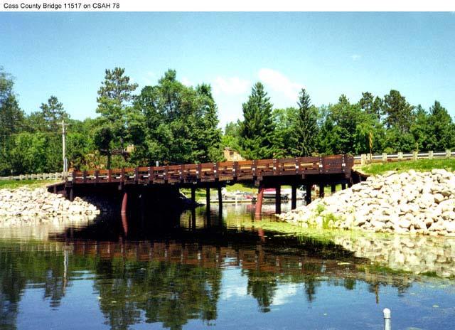
18 3/21/2012 Advantages Timber can be constructed in virtually any weather conditions Do not require special equipment for installation, and can normally be constructed without highly skilled labor Presents a natural and aesthetically pleasing appearance in the natural surroundings Disadvantages The use of timber bridges are limited to lowvolume roads with ADT under 750 Asphalt wearing surface tends to crack from differential deck deflections Not the most economical solution Rule of thumb Normally 1 or 3 spans with a maximum span length of about 40 feet. Simple spans Common Designs Slab Thickness Span Limit Ft Ft Ft Ft Ft. Slab Thickness Span Arrangement Skew 14 in. 3 spans, 18 to º 16 in. 3 spans, 28 to º 18 in. 3 spans, 34 to


19 3/21/2012 Timber Slab Timber Slab 19
20 3/21/2012 Prefabricated Steel Bridges are ideal for recreation and low volume vehicular applications The bridges are shop manufactured with primarily welded connections then shipped to the site ready for installation. Limited field assembly is required for most projects. Typical designs allow for clear spans from 20 to 200 feet. Under certain circumstances, special designs can extend spans to 250 feet. Bridges can be in single or multiple span configurations. Clear spans up to 100 feet can be fabricated and shipped as one piece if contractor capabilities and site considerations allow. Longer spans are built with bolted field splices and shipped as multiple sections. 20

21 3/21/
22 3/21/2012 Advantages include quick installation, low cost bridge, and typically low maintenance. Presents a natural and aesthetically pleasing appearance in the natural surroundings Disadvantages include span limitations of 20 for single barrel, possible debris build-up with multiple barrel arrangements, and a lack of a natural stream bottom for fish unless the invert is lowered and riprapped. 22

23 3/21/2012 Fill heights of less than 2-0 require a distribution slab over the fill area of roadway and shoulders. Class 1 culverts with 2 to 3 of fill and all class 2, 3, and 4 culverts do not require a distribution slab. Cast-in-place distribution slabs to be 6 thick with No. 16 bars at 1-0 transversely and No. 16 bars at 1-0 longitudinally. 23

24 3/21/2012 Distribution slab joints must be centered over barrel segments. Provide 3 minimum granular material per MnDOT spec B2 between barrel and distribution slab. If the fill height range extends into more than one class, use the class with the largest steel areas. Check maximum and minimum fill heights over the full area of roadway and shoulders. 24

25 3/21/2012 If the distance between double barrels is less than 2-0 use either pea rock or lean mix backfill (MnDOT spec. 2520) between the culverts as approved by the engineer. If pea rock is used, provide approved grout seepage cutoff core, minimum 12 thick, between the culvert s two ends. See standard figure for details. Minimum distance between barrels is 6. 25


26 3/21/2012 Offer an alternative for short span bridges up to 42 feet. Larger spans may be considered on a case-by-case basis Advantages include quick installation and natural stream bottom Disadvantages include a higher cost than cast-in-place bridges Typical Spans on local system 24, 28, 32, & 42 26
27 3/21/2012 In General, precast 3-sided structures may be used where: Design span is less than or equal to 42 feet (12.8 m). Larger spans may be considered on a case-by-case basis, but only with prior approval of the Bridge Design Engineer. Span is measured from inside face of sidewalls along the longitudinal axis of the unit; Rise is less than or equal to 13 feet (4m). rise is measured from top of footing/pedestal wall to bottom of top slab; Fill height is less than or equal to 10 feet (3m) but is greater than or equal to 3 feet (1m). fill heights larger than 10 feet (3m) may be considered on a case-by-case basis, but only with prior approval of the Bridge Design Engineer; Skew is less than 30 O ; No foundation limitations exist such as unusually weak soil; 27


28 3/21/2012 No site access limitations exist for transporting and erecting the threesided structures; Clogging from debris or sediment precludes the use of multiple barrel structures; 28

29 3/21/2012 Verify that the correct riprap details are shown. Design 2A Concrete Arches Design 3 Design 2B Design 4 Design 1 29

30 3/21/
31 3/21/
32 3/21/ Span C-SLAB Bridge long (out to out of deck) Velocity = 5.4 FPS Class III riprap Skew angle = 0 degrees Existing bridge is long (11% increase in length) Held to 0.5% minimum profile grade requirement (for drainage), which resulted in a minimum grade increase. Projected ADT = 813 Projected ADT Minimum OT Flood year year year year year 32


33 3/21/2012 Road sag pt. elev. = The overtopping flood is greater than Q100, therefore the design flood is Q
34 3/21/2012 Design Velocity is 5.4 FPS for a Q100 event, but ADT guidelines would suggest a minimum Q25 event for 813 ADT. Q25 event would mean lowering profile significantly, which would create extensive grading cost. Therefore Q100 design was deemed appropriate for this site. Low Member is Elev. = Q100 TW is Elev (HW-0.2 stage inc.) Structure depth check 34
35 3/21/2012 S = 47 feet Min Slab depth = = 1.9 feet or Followed up by a slab design check 35
36 3/21/2012 Check proposed channel bottom feet up and down stream Proposed = 57 feet Hydraulic Engineer s Rec. on plan Hydraulic report 36
37 3/21/2012 Verify Waterway Area, stream velocity and Channel Bottom width using our internal Mathcad spreadsheet. 37
38 3/21/
39 3/21/2012 Plan values 1362 sq ft 5.4 fps 57 ft ft Check riprap size RIPRAP SIZING DETAILS SIZE OF AVG. GRANULAR FILTER WATER VELOCITY AGGREGATE REQUIREMENTS (UP TO) F.P.S. CLASS I 3" 3.86 CLASS II 6" 6" 5.46 CLASS III 9" 9" 6.69 CLASS IV 12" 12" 7.73 CLASS V 15" 15" 8.64 SPEC BOOK ALSO DENOTES THAT THE GRANULAR FILTER SHALL BE 6" UNLESS OTHER DIMENSIONS ARE SPECIFIED (PROBABLY IN THE HYDRAULICS REC.). OCCASIONALLY YOU WILL SEE A PAY ITEM FOR "QUARRY RUN RIPRAP", WHICH IS BASICALLY RIPRAP THAT HAS A MORE ANGULAR SHAPE TO IT. THIS IS HELPFUL FOR THE HIGHER VELOCITIES, WHERE IT INTERLOCKS WITH ITSELF BETTER. Velocity = 5.4 FPS Minimum Class III riprap required 39
40 3/21/
41 3/21/

42 3/21/2012 Single Span PCB Bridge long (out to out of deck) 36M beams spaced at 9-0 Velocity is 6.2 FPS Class IV riprap Skew angle = 0 degrees 42
43 3/21/2012 Low Member is Elev Q100 is Elev Existing bridge is 64 long timber beam span (26% increase in length) Projected ADT < 50 Projected ADT Minimum OT Flood year year year year year 43


44 3/21/2012 Road sag pt. elev. = The overtopping flood is greater than Q100, therefore the design flood is Q

45 3/21/2012 Velocity is 6.2 FPS and is designed for Q100 event, but ADT guidelines would suggest a minimum Q5 event for <50 ADT. Q5 event would mean lowering profile significantly, which would create extensive grading cost. Plus the inplace east approach is already steep. Therefore Q100 design is appropriate for this site. Low Member is Elev. = Q100 TW is Elev (say ok) 45
46 3/21/2012 Check proposed channel bottom approx. 43 feet Proposed = 36 feet approx. 35 feet Hydraulic Engineer s Rec. on plan Hydraulic report 46


47 3/21/2012 Verify Waterway Area, stream velocity and Channel Bottom width using our internal Mathcad spreadsheet. 47
48 3/21/2012 Plan values 520 sq ft 6.2 fps 36 ft ft Check riprap size RIPRAP SIZING DETAILS SIZE OF AVG. GRANULAR FILTER WATER VELOCITY AGGREGATE REQUIREMENTS (UP TO) F.P.S. CLASS I 3" 3.86 CLASS II 6" 6" 5.46 CLASS III 9" 9" 6.69 CLASS IV 12" 12" 7.73 CLASS V 15" 15" 8.64 SPEC BOOK ALSO DENOTES THAT THE GRANULAR FILTER SHALL BE 6" UNLESS OTHER DIMENSIONS ARE SPECIFIED (PROBABLY IN THE HYDRAULICS REC.). OCCASIONALLY YOU WILL SEE A PAY ITEM FOR "QUARRY RUN RIPRAP", WHICH IS BASICALLY RIPRAP THAT HAS A MORE ANGULAR SHAPE TO IT. THIS IS HELPFUL FOR THE HIGHER VELOCITIES, WHERE IT INTERLOCKS WITH ITSELF BETTER. Velocity = 6.2 FPS Class IV riprap called for in plans, conservatively 48
49 3/21/
50 Page 1 of 98
51 Page 2 of 98
52 Page 3 of 98
53 Page 4 of 98
54 Page 5 of 98
55 Page 6 of 98
56 Page 7 of 98
57 Page 8 of 98
58 Page 9 of 98
59 Page 10 of 98
60 Page 11 of 98
61 Page 12 of 98

62 Page 13 of 98
63 Page 14 of 98
64 Page 15 of 98
65 Page 16 of 98
66 Page 17 of 98
67 Page 18 of 98
68 Page 19 of 98
69 Page 20 of 98
70 Page 21 of 98
71 Page 22 of 98
72 Page 23 of 98
73 Page 24 of 98
74 Page 25 of 98
75 Page 26 of 98
76 Page 27 of 98

77 Page 28 of 98
78 Page 29 of 98
79 Page 30 of 98
80 Page 31 of 98
81 Page 32 of 98
82 Page 33 of 98
83 Page 34 of 98
84 Page 35 of 98
85 Page 36 of 98
86 Page 37 of 98
87 Page 38 of 98
88 Page 39 of 98
89 Page 40 of 98
90 Page 41 of 98
91 Page 42 of 98
92 Page 43 of 98
93 Page 44 of 98
94 Page 45 of 98
95 Page 46 of 98
96 Page 47 of 98
97 Page 48 of 98
98 Page 49 of 98
99 Page 50 of 98
100 Page 51 of 98
101 Page 52 of 98
102 Page 53 of 98
103 Page 54 of 98
104 Page 55 of 98
105 Page 56 of 98
106 Page 57 of 98
107 Page 58 of 98
108 Page 59 of 98
109 Page 60 of 98
110 Page 61 of 98
111 Page 62 of 98
112 Page 63 of 98
113 Page 64 of 98
114 Page 65 of 98
115 Page 66 of 98
116 Page 67 of 98
117 Page 68 of 98

118 Page 69 of 98
119 Page 71 of 98
120 Page 72 of 98
121 Page 73 of 98
122 Page 75 of 98
123 Page 76 of 98
124 Page 77 of 98
125 Page 78 of 98
126 Page 79 of 98
127 Page 80 of 98
128 Page 81 of 98
129 Page 82 of 98
130 Page 83 of 98
131 Page 84 of 98
132 Page 85 of 98
133 Page 87 of 98
134 Page 88 of 98
135 Page 89 of 98
136 Page 91 of 98
137 Page 92 of 98
138 Page 93 of 98
139 Page 94 of 98
140 Page 95 of 98
141 Page 96 of 98
142 Page 97 of 98


143 Page 98 of 98