An Effective Method for Crop Monitoring Using Wireless Sensor Network
|
|
|
- Marjory Harris
- 5 years ago
- Views:
Transcription
1 An Effective Method for Crop Monitoring Using Wireless Sensor Network Rakesh M 1 Pramiti J 2, Rashmi Raghunath 2 and *Revanasiddappa M 3 1 Department of Electronics and Communication Engineering, 2 Department of Information Science and Engineering, 3 Department of Engineering Chemistry, PESIT Bangalore South Campus, Hosur Road, Bangalore Abstract Though irrigation is reliable source of water and helps increase productivity, it may also damage the soil making it less productive. The soil tends to become salinized when the water evaporates and leaves salt deposits. Sometimes irrigation leads to water logging of the soil lowering crop yields, and hastening the loss of soil nutrients. Irrigation also leads to loss of soil nutrients (such as zinc, copper, and iron) which plants need to grow. Soil degradation seriously affects agricultural production. About 210 million acres (85 million hectares) of India's farmland are affected. Our keen interest is to change this figure by implementing new sensors technology to the farm land by further improving the drip irrigation to sub surface irrigation using sensor technology. The sensors in the farm land would detect the water level at the root. This water level value given by the sensor is fed to microcontroller which is programmed to control the motor which pumps the water to drip irrigation pipelines.the new thing we have added to the drip irrigation is that we made the pipes reach the root level as a result further saving water by 10 percent. The sensor also detects the ph level of the soil, and gives the information to the farmer whether to add fertilizers to maintain the ph of the soil or to undertake crop rotation. The ph plays a vital role in farming but our farmers never have any idea of this. This will help the farmer to undertake precision farming that is to change the crops based on the ph value of the soil. In India farmers spend a lot of money on the pesticides, this will pollute the neighboring water bodies and kill the aquatic life, and it also enters in the food cycle harms the human being. Therefore we use sensor to regulate water flow in the farm, detect the ph and repel the insects, thereby reduce the use of pesticides. Key Words; Sensor; ph; Pesticides; Insecticides; *Author for correspondence; revanasiddappam@pes.edu 1. INTRODUCTION: Nearly 9 billion mouths to feed by 2050 worldwide; the ratio of arable land to population declining by 40-55%; 3.9 billion people living under severe water stress by 2030.No doubt that agriculture is really important. 1.2 IMPORTANCE OF AGRICULTURE IN INDIA India is an agricultural country, where 70 per cent population is dependent on agriculture. This forms the main source of income. The contribution of agriculture in the national income in India is more, hence, it is said that agriculture in India is a backbone of Indian Economy. 1.3 DECLINE OF AGRICULTURE The decline of Indian agriculture is taking place due to : - Decline in the land available for agriculture due to ever expanding cities and industries and Special Economic Zones. - Decline in land fertility due to non-equipment of required ingredients in soil. - Decline in irrigation facilities due to non-continuance of rivers etc. -Poor economic condition of the farmers resulting in use of low quality seeds, fertilizers etc. - Successive division of land amongst the family members leading to very small area. - Environmental pollution resulting in green house gases and unpredictable climate changes
2 1. 3 MONSOON FAILURE A GREAT THREAT FOR AGRICULTURE IN INDIA It is well known to all about the global climate change. The over accession of human activity on the nature, made some drastic changes over the climate. There are many evidences of artificial rain by china and some other developed countries. Once the climate was a natural phenomena but the human invasion on the climate the whole periodic monsoon lost its periodicity and thus the condition of monsoon fail occurred. These condition made the agriculture sector declined. Now all the farmers quite confused with the aspect of what to farm and when to farm. Sometimes the monsoon rain starts but lasts for a shorter period leaving all crops under the scorching sun and resulting loss to the farmers. 1.4 MAJOR PROBLEMS OF INDIAN FARMERS Irregular rainfall either over irrigation or under irrigation Viral diseases to the crops Adulterated and duplicate seeds Lack of knowledge on the soil fertility,therefore decide random crop Lack of knowledge on ph value of soil, hence use of fertilizer in random rate Insects being resistant to the pesticides, causing them use more; disturbing the crop as well as the ecosystem Top soil being washed by the rain Animal attack on the crops, animals like wild pig, elephants etc No good soil and water health check stations available in the nearby locality Marketing problems etc 1.5 SOLUTION TO SOME OF THE MAJOR ISSUES Our sensor system is a collection of feedback loop system. The sensors would solve the problems such as Irrigation control to the best possible extent Soil fertility maintained Pesticides usage do and don ts Fertilizers usage based on the soil health Animal attack security Pesticide usage reduced Labours reduced 1.6 WORKING PRINCIPLE The system is a collection of sensors were each of them has a specific task assigned. The task would be controlled by the controller which is programmed based on the required operation. The sensors would perform tasks such as detecting the moisture content of soil, ph of the desired soil and water sample, light intensity of the green house, temperature of the farm, water level of the tank, and power distribution control to the entire farm, on and off of the insect repellent based on the requirement and provide a database for analysis. This data would in turn give conditions to be analysed by the controller and regulate the water supply, decide if the soil is good for the desired crop, check if the soil health in good condition or not, based on the research database of Biotech engineers stored in the controller memory there by forming a feedback loop system. The sensors are to be placed in the location where the average farm parameters can be analysed. One sensor controller to be placed in the green house for the control of the light as well as the temperature along with moisture for the germinating saplings. Now the data of each sensor is transmitted to the main controller by wireless module in turn in the form of text message is updated to the farmer time to time. The
 Relay- Relay is an electrically operated switch ph electrode Temperature sensor- Solar panel- Rechargeable")

3 encoding of the different sensors data use the error controlling code book of information theory and coding of Shannon. 2 HARDWARE REQUIREMENTS Microcontroller Power supply regulator- Display unit(led /lcd) Relay- Relay is an electrically operated switch ph electrode Temperature sensor- Solar panel- Rechargeable battery- Cmos ADC Serial EEPROM AT2402- GSM modem 2.1 SOFTWARE REQUIREMENTS Embedded C Keil Micro Vision IDE Flash Magic 2.2 ANALOG SENSORS 2.3 PRECISION CENTIGRADE TEMPERATURE SENSORS GENERAL DESCRIPTION The LM35 series are precision integrated-circuit temperature sensors, whose output voltage is linearly proportional to the Celsius (Centigrade) temperature. 2.5 FEATURES Calibrated directly in Celsius (Centigrade) Linear mv/ C scale factor 0.5 C accuracy guarantee able (at +25 C) Rated for full 55 to +150 C range Suitable for remote applications Low cost due to wafer-level trimming Operates from 4 to 30 volts Less than 60 μa current drain Low self-heating, 0.08 C in still air Nonlinearity only ±1 4 C typical

 is a resistor whose resistance decreases with increasing incident light intensity; in other words, it exhibits photoconductivity.")

4 Low impedance output, 0.1 W for 1 ma load 2,6 TEMPERATURE SENSOR INTERFACE TO MICROCONTROLLER The reason to make a soil temp sensor is so that we can use it to offset the simple soil moisture sensor. The reason for this is because soil resistance changes with temperature. So to add another layer of accuracy, we can include a temperature sensor near our moisture sensor. Then we can use the temperature to offset the data from the moisture sensor to help mitigate the false dry reading caused by changes in temperature. 2.7 LIGHT SENSOR A photoresistor or light dependent resistor (LDR) is a resistor whose resistance decreases with increasing incident light intensity; in other words, it exhibits photoconductivity. It can also be referred to as a photoconductor or CdS device, from "cadmium sulfide," which is the material from which the device is made and that actually exhibits the variation in resistance with light level. Note that although CdS is a semiconductor, it is not doped silicon. 2.8 SOIL MOISTURE SENSOR The resistive type of moisture sensor is the most crude. It uses the two probes to pass current through the soil, and then we read that resistance to get the moisture level. More water makes the soil conduct electricity more easily (less resistance), while dry soil conducts electricity more poorly (more resistance). 2.9 ph SENSOR
 that is measured and displayed as ph units by the meter.")
5 The ph probe measures ph as the activity of the hydrogen cations surrounding a thin-walled glass bulb at its tip. The probe produces a small voltage (about 0.06 volt per ph unit) that is measured and displayed as ph units by the meter. In the most basic sense a ph probe is a very simple single cell battery, where the voltage produced is proportional to the hydrogen ion concentration around the probe and therefore proportional to the Log of the hydrogen ion concentration as expressed here ph = -log10(ah) BASIC DESIGN A typical probe has an impedance of anywhere between 10MΩ and 100MΩ, and since 100MΩ*1nA=.1v even having a single stray nano amp can throw our measurement off by almost 2 entire ph units. The goal then is to choose an op amp that is adequate enough that will not load down the probe but that also has characteristics which will keep both the cost down and the accuracy up. When combined with the previous considerations about probe age and drift, a basic roadmap is made on how we can simply and effectively amplify and interface a ph probe signal WATER LEVEL CONTROL AND GROUND MOISTURE LEVEL REGULATOR- Whenever the controller through its sensors gets to know that the water in less than the desired level either in the ground or the tank the controller send a high to the relay to power up the for filling the tank. In the other case the relay would on the motor controlling the pressure of a drip irrigation system or the sprinkler, the modern way is the subsurface farming. 3 ANALOG TO DIGITAL CONVERTER The ADC0808, ADC0809 data acquisition component is a monolithic CMOS device with an 8-bit analogto-digital converter,8-channel multiplexer and microprocessor compatible control logic. The 8-bit A/D converter uses successive approximation as the conversion technique. 3.2 CONVERTER CHARACTERISTICS If sensors output is much less than 5 volts, we can increase the resolution of the converter by connecting VREF to a voltage larger than the highest voltage you expect to measure.to illustrate, consider a sensor whose output ranges from 0 to 0.5 volt. The 8 bit digital output of the convert represents a number from 0 to 255. If VREF is 5 volts, each count equals 5/255 or 19.6 millivolts. A 0.2 volt analog input results n a

6 count of 10, while a 0.5-volt input results in account of 26. If your input goes no higher than 0.5volt, your count will never go higher than 26, and the measured value will be accurate only to within 20 millivolts,or 1/255 of full-scale. ADDRESS LINE A, B, C The device contains 8-channels. A particular channel is selected by using the address decoder line. The TABLE 1 shows the input states for address lines to select any channel. 4 PERIPHERALS 4.1 RELAY Relays are devices which allow low power circuits to switch a relatively high Current/Voltage ON/OFF. For a relay to operate a suitable pull-in & holding current should be passed through its coil. Generally relay coils are designed to operate from a particular voltage often its 5V or 12V. The above circuit diagram shows the basic relay driver circuit. As you can see an NPN transistor BC547 is being used to control the relay. The transistor is driven into saturation (turned ON) when a LOGIC 1 is written on the PORT PIN thus turning ON the relay. The relay is turned OFF by writing LOGIC 0 on the port pin. A diode (1N4007/1N4148) is connected across the relay coil; this is done so as to protect the transistor from damage due to the BACK EMF generated in the relay's inductive coil when the transistor is turned OFF. When the transistor is switched OFF the energy stored in the inductor is dissipated through the
7 diode & the internal resistance of the relay coil. Normally 1N4148 can be used as it is fast switching diode with a maximum forward current of 300ma. This diode is also called as free-wheeling diode. 4.2 ANIMAL SECURITY Electric current (AMPS) only flows when a circuit is completed between a positive and negative terminal. Diagram A In this diagram the current cannot flow from the positive terminal to the negative terminal because the switch is open. Diagram B In this diagram the switch is now closed, allowing the current to flow from the positive terminal through the light bulb (lighting the bulb) to the negative terminal. An electric fence circuit is made on a larger scale. The energizer fence terminal (positive) is connected to the insulated fences wires, and the energizer earth terminal (negative) is connected to galvanised metal stakes driven into the ground. The same 'circuit completion' (as in Diagram B) is necessary before the animal gets a short, sharp but safe shock. An animal standing on the ground and touching the electrified wires will complete the circuit like the closed switch in Diagram B above. The shock is sufficiently memorable that the animal never forgets. 4.3 INSECT REPELLENT The block has an insect repellent circuit.the Insect repellent is an oscillator circuit which produces ultrasonic sound waves repelling the insects away. The cmos 4047 is used in this circuit as the oscillator.this electronic circuit is an insect repellant using IC CMOS This insect repellant circuit designed by Graham Maynard the circuitry consists of a phase locked loop (CMOS 4047) wired as a 22KHz oscillator. The output is amplified by a pair of complimentary output transistors and drives a Motorola 3.25 inch Piezo. Current drain is around 120mA so an external power supply is recommended.
8 The piezo used was a standard 85mm square Motorola Horn, Maplin part number WF09K or WF55K. These are rated +/-3dB to 28kHz. 4.4 WATER LEVEL DETECTOR The circuit uses 6 transistors, 1 NE555 timer IC, a relay and few passive components. Probe D is positioned at the bottom level of the tank while probes A, B and C are placed at full, half and medium levels of the tank respectively. The level sensing part of the circuit is built around transistors Q1, Q2 and Q3. When water level is below the quarter level probes A, B and C are open and the transistor Q1, Q2 and Q3 remains OFF. When the water level rises and touches the probes the corresponding transistors gets biased and switches ON. Resistors R1, R2, R3 limit the bases current of corresponding transistors while resistors R4, R5, R6 limit their collector current. LEDs D1, D2 and D3 provide a visible indication of the current water level. Resistor R8 is a pull up resistor for the trigger pin of the NE555. Capacitor C3 couples the collector of Q1 to the trigger pin of NE555 and facilitates edge triggering whenever the transistor Q1 goes ON. A monostable circuit can be made edge triggered by connecting the trigger signal to the trigger input pin through a capacitor. The capacitor blocks DC and passes sudden changes. 4.5 LIGHT INTENSITY CONTROL The light intensity control is used in green house, it s a feedback mechanism.the light intensity control device (Fig. 1, above) uses a standard 24-h timer toactuate a 120 volt DPST relay which either allows charging or discharging of C, through a 2 M Ohm linear potentiometer (R 1 ) during the period of light intensity change. Independent control of the dusk and dawn periods can be achieved by adding a second 2 M Ohm potentiometer in the above Figure. 5 RESULTS AND DISCUSSION 5.1 HARDWARE SNAPSHOTS
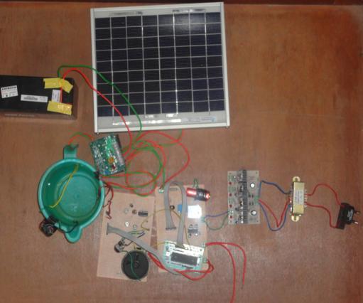
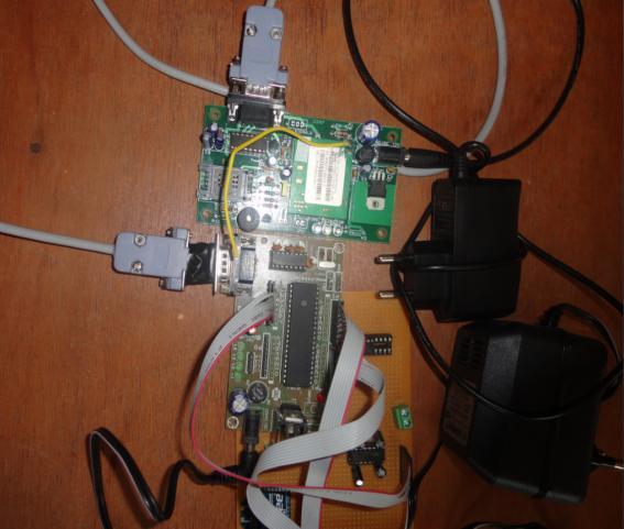
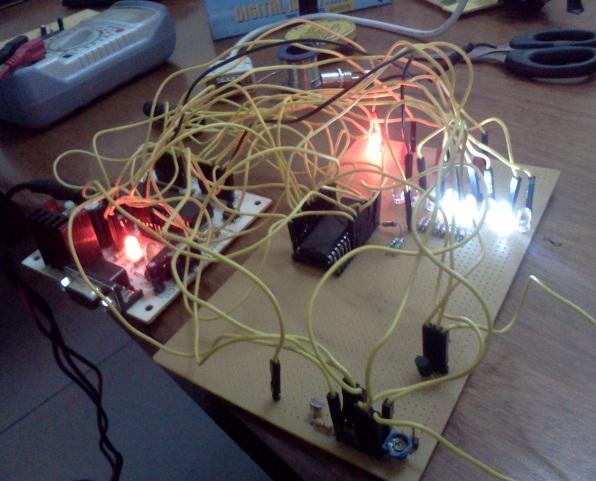
9 POWER CONTROLLER SENSOR CONTROLLER


10 5.2 SOFTWARE SNAPSHOTS KEIL WINDOW MC SELECTION HEX FILE CREATION FLASH MAGIC BURNING TO MC
11 5.3 POWER CONTROLLER START ON THE RELAY TO AC POWER A CHECK IF AC IS ON YES NO ON THE SOLAR BATTERY RELAY DISPLAY WHICH IS BEING USED CHECK FOR SWITCH ON ON THE INSECT REPLLENT/SECURITY/ WATER LEVEL CIRCUIT OFF DISPLAY WHICH CIRCUIT IS USED B
12 B CHECK TANK WATER LEVEL NORMAL LOW ON PUMP SEND SIGNAL TO MAIN CONTROLLER CHECK FOR HANSHKING SIGNALS NO A YES TRANSMIT SENSOR S DATA A
13 5.4 SENSOR CONTROLLER BLOCK2 START C READ SENSOR VALUES STORE THE RESULT CHECK FOR HANDSHAKING SIGNAL NO YES TRANSMIT DATA CHECK FOR ANY ON OFF CONDITION ON AND OFF THE REQUIRED PEIPHERAL C
14 5.5 SENSOR CONTROLLER BLOCK3 START D READ SENSOR VALUE STORE THE VALUES CHECK FOR THE ph SWITCH OFF D ON DELAY 30 SECONDS CALCULATE ph VALUE DISPLAY E
15 E NO CHECK FOR HANDSHAKING SIGNALS D YES TRANSMIT DATA CHECK FOR THE HANDSHAKING ON AND OFF YES SWITCH THE PERIPHERALS NO D
16 5.6 MAIN CONTROLLER BLOCK4 START INITIALIZE MEMORY DEVICE CHECK TIMER SWITCH OFF ON START CONTROLLLER TIMER ON THE GSM MODULE TO ACTIVE MODE E SEND HANDSHAKING SIGNAL TO EACH SENSOR RECEIVE THE SENSOR OUTPUT VALUES F
17 F YES CHECK FOR ERRORS E NO STORE THE VALUES CHECK DATABASE FOR STANDARD VALUES NO G YES OFF THE REGULATE CIRCUIT CHECK IF TIMER IS ON AND IF IT HAS REACHED ITS SPECIFIC TIME E TRANSMIT THROUGH GSM MODEL E

18 G ON THE REGULATOR CIRCUIT SENT MESSAGE TO FARMED BY GSM MODEL E 5.7 CONCLUSION The farmer need not worry of the irrigation control Soil fertility is checked time to time Reduce the use of pesticides there by improve the ecosystem Complete automation enabled Can control the farm from elsewhere The database time to time tells which fertilizer is good for soil and season The database tell the farmer when to undertake crop rotation Problem of crop disaster by animals is completely avoided The database provide analyses of predicting monsoon easier The temperature of farm can be analyzed to check if its good for the crop or not REFERENCES Microcontroller and Embedded Systems by Mazidi 2. C Programming for Microcontrollers by Joe Pardue 3. Cmos
19 4. Connections file:///e:/users/shravani/downloads/pojecthtml/8051%20development%20system%20circuit%20 Board.htm 5. Datasheets 6. lcd 7. insect repellent 8. Easy PC Interfacing by R.Penfold adc