VVUQ of Computational Modeling and Simulation Software to Predict the Durability of Medical Devices. May 15, 2015
|
|
|
- Lizbeth Wilkerson
- 5 years ago
- Views:
Transcription

1 VVUQ of Computational Modeling and Simulation Software to Predict the Durability of Medical Devices May 15, 2015 Sanjeev Kulkarni, Robert G. Tryon, 1Animesh Dey
2 Who is VEXTEC? Founded in 2000: Over $25 million from the United States Department of Defense Innovative Research programs for Technology Development Proprietary Software and Seven Patents: Virtual Life Management (VLM ) generates VIRTUAL TWIN Customers: Federal Government and Industries (Aerospace, Automotive, Electronics, Energy, MEDICAL DEVICES) Value Proposition: Help companies improve products and reduce cost New products to market quickly Improve reliability of existing products Reduce physical and prototype testing requirements Forecast product durability and manage product life cycle risk Business Model: Hybrid Consulting 3 Services, Software Licensing and Training VEXTEC accepted into FDA s Medical Device Development Tool (MDDT) pilot Program

3 Uncertainty Management Virtual Twin representation of Uncertainty Propagation across multiple levels of a system A probabilistic multi-disciplinary uncertainty management analytical tool that links computational models How will changing the input uncertainty of the analysis impact the uncertainty in the results? Can the uncertainty be updated based on actual usage and observed damage state? What is the sensitivity to uncertainty? Model 1 Model 2 Model 3 4
4 Uncertainty Management How general is this Uncertainty Management Tool? General Tool Virtual (In Silico) Clinical Trial Post Market Surveillance Therapy Effectiveness and Limits Virtual Patient Device or Therapy Physician or Process 5
 if no failure Measured difference in maximum Von-Mises stress between Conditions 1 and 2 Condition 2: B Von Mises Stress; Max Stress=YY")
5 COU: Cardiac Leads Cond1: A +/-a Cond2: B +/-b Condition 1: A Von Mises Stress; Max Stress=XX ksi Simulation of two test conditions Displacements A and B Cycling between maximum displacement and 0 displacement Cycling to 1E10 cycles and Runout (suspension) if no failure Measured difference in maximum Von-Mises stress between Conditions 1 and 2 Condition 2: B Von Mises Stress; Max Stress=YY ksi 6
6 Uncertainty Management Virtual Twin of a cardiac / defibrillator lead design Estimate fatigue life Sensitivity of uncertainty in input variables and Sensitivity of modeling approximations. Flow of the design analysis: Manufacturing process model provides residual stress Structural analysis provides stresses model Microstructural material model predicts fatigue Sources of uncertainty: Coil winding uncertainty Predicted residual stress uncertainty Structural geometry uncertainty Loads and boundary conditions uncertainty FEA mesh size uncertainty Material microstructure uncertainty Cumulative Probability Distribution Function (CDF): Cycles to failure considering all uncertainties vs. actual test results Fatigue durability results are highly sensitive to uncertainty in residual stress Simulations performed at different residual stress levels Good correlation for a calibrated value of residual stress 7
 Abstraction")


7 ASME V&V Fig 4 Mathematical Modeling Reality of Interest (Component, Subassembly, Assembly, or System) Abstraction Conceptual Mode Physical Modeling Mathematical Model Physical Model Code Verification Calculation Verification Implementation Computational Model Calculation Preliminary Calculations Implementation Experiment Design Experimentation Revise Appropriate Model or Experiment Simulation Results Uncertainty VEXTEC Quantification VLM Validation Experimental Data Uncertainty VEXTEC Quantification VLM Simulation Outcomes Quantitative Comparison Experimental Outcomes Acceptable Agreement? No 8 Yes Next Reality of Interest in the Hierarchy
 the CM&S")
8 ASME V&V 40 Draft Figure 2 VLM can be used to explore the region outside the Validation Domain as well as at the edges (or even beyond) the CM&S assumptions 9


9 ASME V&V 40 Draft Figure 3 PIRT Existing VV Data M&S Plan Purpose Define COU Assess Model Risk Establish Credibility Threshold Establish Work plan for VV VLM can play a Key Role in each step of the Credibility Assessment Strategy especially in the Execution Step where Uncertainty Quantification is important No Is the plan Achievable? YES Execute predefined M&S and V&V plan 10 No Document M&S And VV plan and findings Is the CM&S credible for COU? YES


10 How the VLM Process Compares with Conventional Methods? VLM approach predicts failures Percent of Shafts 10 Load Applied to Shaft Shaft Failures Conventional view of component Load Bearing Capacity of Shaft 60,000 75,000 lbs. per square inch (psi) Fatigue strength is traditionally determined by testing 11 VEXTEC s view of component, grains & damage


11 VLM Predicts How, When, Where, and Why Damage Occurs Standard Industry Analysis VLM Analysis Design & Stress Life & Where & Why 12


12 VLM: Grain FEA Component Fleet Component Design Configuration Material Configuration VLM Computational Processing Mapping the Elements Component Simulation Fleet Simulation 13


13 VLM: Grain FEA Component Fleet 27,943 Tooth Life: 15,932 cycles Failure Cause: Defects Component Life: 14,334 cycles 22,113 18,961 22,229 25,342 17,561 24,793 Integrate VLM Results with FEA VLM Integration for Entire Component Repeat Sequence for Each Tooth 1 st Virtual Twin Gear Simulated VT 1, VT 2, VT 3 VT 1,000 Run 1,000 Simulations 14
14 Uncertainty Management Virtual Twin of a cardiac / defibrillator lead design Estimate fatigue life Sensitivity of uncertainty in input variables and Sensitivity of modeling approximations. Flow of the design analysis: Manufacturing process model provides residual stress Structural analysis provides stresses model Microstructural material model predicts fatigue Sources of uncertainty: Coil winding uncertainty Predicted residual stress uncertainty Structural geometry uncertainty Loads and boundary conditions uncertainty FEA mesh size uncertainty Material microstructure uncertainty Cumulative Probability Distribution Function (CDF): Cycles to failure considering all uncertainties vs. actual test results Fatigue durability results are highly sensitive to uncertainty in residual stress Simulations performed at different residual stress levels Good correlation for a calibrated value of residual stress 15


15 Cardiac Leads Material Model Grain Size Residual Stress Particle Size J. E. Schaffer: Masters Thesis, Purdue,


16 Cardiac Leads Material Model Nucleation Small Crack Growth Near-initiation, cracked TiN particle Crack front arrest at microstructural features. Chevron crack-initiating feature Striation spacing at crack front J. E. Schaffer: Masters Thesis, Purdue,


17 Cardiac Leads Material Model 18
18 COU: Cardiac Leads Cond1: A +/-a Cond2: B +/-b Condition 1: A Von Mises Stress; Max Stress=XX ksi Simulation of two test conditions Displacements A and B Cycling between maximum displacement and 0 displacement Cycling to 1E10 cycles and Runout (suspension) if no failure Measured difference in maximum Von-Mises stress between Conditions 1 and 2 Condition 2: B Von Mises Stress; Max Stress=YY ksi 19
19 Cardiac Leads VLM Simulation Define geometry and stress with FEA Define microstructure with metallography Run Simulation Calibrate to residual stress profile with experimental data 20


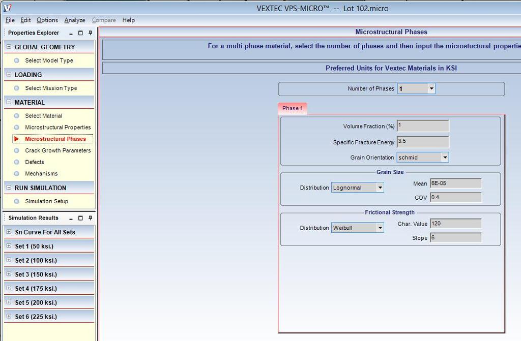


20 Cardiac Leads VLM Simulation 21

21 Cardiac Leads VLM Simulation Virtual Design of Experiments Applied displacement Residual stress profile Inclusion size distribution Top durability drivers Residual Stress 10% improvement yields 60% improvement in mean total life Inclusion Size 50% smaller inclusion size yields 25% improvement in mean total life Inclusion Density- 50% lower inclusion density; No significant impact Trade-off threshold exists between residual stress and inclusion size 22


22 Cardiac Leads: Summary and Outcomes Summary Simulated fatigue buckling test under 2 load conditions Virtual DOE consisted of 9600 individual coil simulations Outcomes / Next Steps Sensitivity study around particle size, density and residual stress Determined residual stress to be a calibrated value - new knowledge Developed Insights - Design alternatives, Material substitution, Vendor management Potential - Sensitivity analysis, Design trade studies, Supplier controls, Design optimization Add Realism Coiling Simulation for Residual Stresses - Underway 23 VDOE Results for Residual Stress

23 MDDT Cardiac Leads Chronology Medical Device Development Tools (MDDT) Draft Guidance - FDA November 2013 MDDT Pilot Program Announced August 2014 Began Accepting Nominations September 2014 VEXTEC Submitted in November 2014 and FDA sent Acceptance in December 2014 Highlights VEXTEC VLM at a mature stage of development FDA recognizes that VLM meets a key public health need Major Efficiencies to be gained in Device Development and Evaluation Time VEXTEC currently working with OEMs, Software Vendors and FDA staff Seeking Partners / Collaborators. VEXTEC has been selected into the Medical Device Development Tools (MDDT) Pilot Program 24
24 Summary / Takeaways Virtual Life Management and Virtual Twin represent a general framework that incorporates systems realism including uncertainty management and design sensitivity / variability The framework supports key aspects of VVUQ standards ASME V&V and proposed ASME V&V 40 A Cardiac Pacemaker Leads implementation was shown as an example with key insights Ability to Virtually Simulate Bench Tests Study sensitivity of Microstructural Parameters and Residual Stresses on Component Life Evaluate of Significant Outcomes Design Alternatives, Material Substitution and Vendor Management Demonstrate Potential for Major Gains in terms of time and cost of Design Development and Evaluation Methodology Recognized by FDA and accepted into the Medical Device Development Tool (MDDT) Pilot program 25

25 Thank you VLM software is applicable throughout a product s life cycle, constantly growing in capability and value 26