Dose Reduction during EVAR in Hybrid Room. Multicentric Study
|
|
|
- Mitchell Dawson
- 5 years ago
- Views:
Transcription

1 Dose Reduction during EVAR in Hybrid Room Multicentric Study Golden rules to reduce radiation dose in the hybrid room to a minimum Stéphan Haulon, MD, Best Practice from Lille Aortic Center Aotic Centre, Hôpital Marie Lannelongue, Paris Sud, France
2 Disclosures Research support, Consulting Cook Medical, GE Healthcare


3 Literature overview Where do we stand?
4 Literature overview Where do we stand? Median DAP (Gy.cm²) values reported in the Literature for Bifurcated EVAR procedures
 values reported in the Literature for complex EVAR procedures x3")
5 Literature overview Where do we stand? Median DAP (Gy.cm²) values reported in the Literature for complex EVAR procedures x3 to 15 times higher
:424-30 b. G. Panuccio at al.")
6 Literature overview Where do we stand? Operator exposure over the lead apron per procedure type c The limit for occupational exposure suggested by the ICRP is maximal 50 msv/year d. a. Patel A.P. et al, Occupational Radiation Exposure During Aortic Procedures, Eur J Vasc Endovasc Surg Oct;46(4): b. G. Panuccio at al. Comparison of indirect radiation dose estimates with directly measured radiation dose for patients and operators during complex endovascular procedures. J Vasc Surg 2011;53: c. Hertault A et al. Impact of Hybrid Rooms with Image Fusion on Radiation Exposure during Endovascular Aortic Repair, Eur J Vasc Endovasc Surg Oct;48(4): d. International Commission on Radiological Protection, Recommendations of the International Commission on Radiological Protection. ICRP Publication 60. Ann ICRP


7 System Basics Detector High Detective Quantum Efficiency DQE Auto Exposure Management dose versus image quality and all detector components are summarized into DQE AutoEx optimizes imaging parameters, based on the estimated patient thickness, automatically and in real time When thickness increases, imaging chain loop and auto exposure increases dose rate to maintain same image quality at the detector level. Title or Job Number XX Month 201X 7

8 Golden Rules
9 Before the procedure Title or Job Number XX Month 201X 9


10 Before the Procedure Careful Pre-operative planning to define best working angulations


11 Before the Procedure 3D Volume preparation for Image Fusion
12 In the Hybrid Room Title or Job Number XX Month 201X 12

13 No lead, No X Comparison of operator eye exposures when working from femoral region, side, or head of patient 1 M.J. Ray, W.B. Taylor III, J.T. Weber, C.M. Savage. Comparison of Operator Eye Exposures When Working from Femoral Region, Side or Head of Patient, Journal of Vascular Interventional Radiology, Volume 23, Issue 3, Supplement, Page S127, March 2012


14 Optimize System Geometry Activate InnovaSense * * Option

15 Dose Optimize Reduction System in the Geometry Hybrid Room Why? Haqqani J Vasc Surg 2012

 of PCI activities on Innova IGS520 at CHU")
16 Dose Optimize Reduction System in the Geometry Hybrid Room Why? Innova Sense patient contouring technology automatically positions the detector as close as possible to the patient Air Kerma Dose Reduction by up to 25% 1. Retrospective analysis of 956 patient rom one-year usage (2013) of PCI activities on Innova IGS520 at CHU Brest. Simulated with the user working at max SID (120cm) instead of optimized SID obtained with InnovaSense
17 Use lowest acceptable protocol & frame rate 100% 50% IQ+ Normal 30fps IQ+ Normal 15fps 24% RDL+ Normal 15fps 1 Dose ratios mentioned are air kerma rate ratios measured according to IEC conditions. Field Of View of 20cm. In clinical use, the results of dose reduction techniques will vary depending on the clinical task, patient size, anatomical location and clinical practice. Physicians assisted by a physicist as necessary has to determine the appropriate settings for each specific clinical task. 9% RDL+ Low 15fps 5% RDL+ Low 7.5fps 2% RDL Low 3.75fps


 Find")

18 Routinely use Image Fusion and get the best of your pre-operative dataset Register with Bi-view (2D/3D registration) Find working position without X-ray Fine tune 3D mask at table side Use Digital Zoom

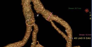
19 Dose Avoid Reduction Magnification, in the Hybrid Use larger RoomFOV & Collimation instead Why? Some facts : Switching from FOV 30cm to FOV 16cm increases dose rate by ~2 Mentice, Gothenburg, Sweden
 DAPtot x (1-0,6) = 12 Gy.cm² (60% collimated) DAPsaved = 18 Gy.")
20 Dose Avoid Reduction Magnification, in the Hybrid Use larger RoomFOV & Collimation instead Why? Some facts : 60% collimated area is 60% dose saved. On a bifurcated EVAR exam of 30 Gy.cm², 18 Gy.cm² can be saved just by using collimation DAPtot = 30 Gy.cm² (non-collimated) DAPtot x (1-0,6) = 12 Gy.cm² (60% collimated) DAPsaved = 18 Gy.cm² (dose savings) In Lille, Baseline for bifurcated EVAR is 12Gy.cm² an in average image is collimated by 60%. 20


21 Limit DSA runs In term of dose, 1 DSA image ~ 500 fluoro images Prefer fluoroloop instead of DSA, except for completion angio or difficult situations 21


22 Limit DSA runs Fluoro Roadmap Use fluoro roadmap


23 Limit C-arm angulation Operator Dose rate LAO/RAO C B A When LAO/RAO angle are >30, patient & operator dose rate increases exponentially. Same with CRA/CAU >15 Haqqani J Vasc Surg 2012

24 Could these results be achievable elsewhere? Maimonides Lille Takaï Toulouse Birmingham 24
25 Could these results be achievable elsewhere? Methodology Bifurcated EVAR All centers using same Hybrid Room (Discovery IGS from GE Healthcare ) Each center has received a dose and fusion imaging training before enrolling patients Monitoring dose and practice via Dosewatch, cloud-based tracking system
26 Pre study Result The Importance of practice feedbacks Site X prior the study 7,5fps

 32% Frame Rate (% of Total DAP) 100% FOV (% of Total DAP) Angulation (% of Fluoro Time & DAP) 18%")
27 After Practice analysis and dedicated training Number Of Cases 8 MeanDAP 16.5Gy.cm² MeanAK 0.105Gy Mean Fluoro Time 14.05min Mean SID 1.15m 30 Collimation (% of estimated collimated area per FOV) 0% 20% 40% 60% 80% 100% Irradiated Collimated Acquisition Type (% of Total DAP) 32% Frame Rate (% of Total DAP) 100% FOV (% of Total DAP) Angulation (% of Fluoro Time & DAP) 18% 8% 19% 81% 68% 100% 74% Fluoro DSA 7,5 30 DAP divided by 2 thanks to better FOV & Collimation management
28 REVAR study preliminary results Median DAP (Gy.cm2) Median Air Kerma (mgy) Median Fluoro time (min) Site 6 Site 5 Site 4 Site 3 Site 2 Site 1 Site 6 Site 5 Site 4 Site 3 Site 2 Site 1 Site 6 Site 5 Site 4 Site 3 Site 2 Site 1 0,0 10,0 20,0 30,0 0,0 50,0 100,0 150,0 200,0 0,0 5,0 10,0 15,0 20,0 Achieving consistent low dose results for EVAR across sites Median DAP < 30 Gycm2, AK < 200 mgy
29 Going beyond the Hybrid OR and considering the full hospital stay Title or Job Number XX Month 201X 30


30 HOME OR workflow at CHU Lille Before Planning prep in reading room Fusion prep in control room send Follow-up CTA NOW Planning & Fusion prep anywhere automatic recall Guidance and completion CBCT Follow-up Ultrasound Combining planning, sizing and fusion preparation in one step to improve OR workflow efficiency GE INTERNAL USE ONLY
 -68% Dose (msv) a. *Hertault A et al.")
31 Significant reduction in overall dose and contrast Median radiation exposure of CBCT a is 7 Gy.cm Contrast and dose to patients during their hospital stay -50% DSA+CTA CBCT+U/S 50 0 Contrast volume (ml) -68% Dose (msv) a. *Hertault A et al. Benefits of Completion 3D Angiography Associated with Contrast Enhanced Ultrasound to Assess Technical GE INTERNAL Success after USE EVAR, ONLY Eur J Vasc Endovasc Surg (2015) 32

32 Title or Job Number XX Month 201X 33 GE INTERNAL USE ONLY
33 Conclusion Low dose technology design must be associated with good practices Each step has a huge impact on dose results Routine use of fusion imaging with full control at table side enables to achieve low dose results for EVAR in multiple centers Integrated workflow of EVAR ASSIST from sizing to CBCT including fusion imaging help reduce total dose & contrast throughout patients hospital stay