Spying on Cells: Cellular and Subcellular Analysis using Novel Polymeric Micro- and Nanostructures. Xin Zhang Associate Professor.
|
|
|
- Marybeth Lambert
- 5 years ago
- Views:
Transcription


1 Spying on Cells: Cellular and Subcellular Analysis using Novel Polymeric Micro- and Nanostructures Xin Zhang Associate Professor Boston University US-Korea Nano Forum April 2008


2 Road Map of Nanobio-sensors How can we best monitor living cells in-situ and continuously to understand, characterize, and model functional behavior at the cellular levels so as to explore biosensor specificity and flexibility for distinct responses to different combinations of stimuli? Many key problems in biochemical sensing can be solved by converting biological or chemical response to an electrical, optical, or mechanical signal using micro/nanosystems. The use of living cells as sensor elements provides the opportunity for high sensitivity in a broad range of biologically active substances and physical stimuli that affect cell responses. Nano-optical sensors Nanoelectrical sensors Ion channel activity Cell adhesion Gene expression Cellular force Nanomechanical sensors


3 Polymer Pillar Array High Aspect Ratio Low Aspect Ratio Spacebars indicate 5 µm Laboratory for Microsystems Technology, Boston University


4 Realization of 3D Structures Utilizing the micromolding process, complex structures, varying in both lateral dimension and height, are fabricated. Replicated from the same master template Elevated sidewalls are to provide vertical surfaces for cell attachment. o This may avoid the artificial polarization of cells induced by conventional dishes, thus allowing a more in-vivo-like cellular morphology. 10 µm 10 µm Embedded Pillars Sidewalls Polymeric posts placed between the sidewalls are to further enhance cell attachment. Laboratory for Microsystems Technology, Boston University Posts

5 Experimental Setup for Cellular Force Measurement The cardiac myocytes were isolated from Wistar rats Liquid pump Feedback control z y The cells were plated on the fabricated structures Heating rod Inlet Electrical contact pair Thermometer Outlet O Vacuum pump x Fluidic Connection Electrical Connection Inverted Microscope Buffer solution + - z y Perfusion chamber O x Waste solution Inlet Outlet Inverted microscope CCD camera PDMS chip Thermometer probe Computer system for imaging analysis 37 C; Real time; Live cell; CO 2 preferable gas concentration


6 PDMS pillars Myocyte 10 µm

7 Length (µm) Deformation Isolation between Cells B C A B C and the Base Substrate Myocyte Pillars Time (s) 10 µm Conditions - The isolated myocytes were plated on a PDMS substrate with pillars of aspect ratio 2:1, allowing 24 hours for adhesion. - The myocytes were stimulated by a digital pacer with a periodical voltage pulse (DC 20V at 0.5 Hz), which provided an additional electrical potential besides the action potential of the myocytes to activate the contractile proteins. The underlying pillar has periodical displacement with the cell contraction The pillar away from the cell does not represent a obvious periodicity. The displacement is on the noise level. F F
 Image Processing Extract and remove background")


 150 nn Residual")
8 Image Processing for Cellular Force Measurement (a) (b) Image Processing Extract and remove background nonuniformity Applying thresholding to the image Locate individual pillars Compare derived pillars array with a reference Derive the deformation map and force map Laboratory for Microsystems Technology, Boston University (c) Binary array Pillar number Residual noise from the cell (d) Histogram 5 µm Area of pillar top (µm 2 ) 150 nn Residual noise from the cell
 (x component) Cellular force (nn) 180 170 160 150 140 130 200 160 120 80 40 0-40 -80-120 -160-200 300 200 100 y (µm) (a)")
 The force evolution reveals the alignment of motile units in cardiac myocyte, which conforms to the physiologic fact.")
9 Contraction Force Analysis Force measurement with subcellular resolution Force component along contraction axis Force component along transverse axis Force evolution measured in real time Cellular force (nn) (x component) Cellular force (nn) y (µm) (a) Cellular force (nn) (y component) y (µm) x (µm) (b) x (µm) The force evolution reveals the alignment of motile units in cardiac myocyte, which conforms to the physiologic fact. (c) 1 2 Time (s) (d) 1 Time (s) 2
10 Force Evolution during Chemical Perfusion Chemical Sensing Drug evaluation Cell mechanics study Pathology investigation etc. Validation of the inotropic effect of the cardiac myocytes in response to the β-adrenergic stimulation Currently validated by an increase of inward calcium current, a greater rate of release of calcium ions from the sarcoplasmic reticulum (SR), and an accelerated reuptake of calcium into the SR 15.2 Displacement (µm) (b) (a) Time (s) ~ 21.2 nn ~ 29.8 nn Laboratory for Microsystems Technology, Boston University
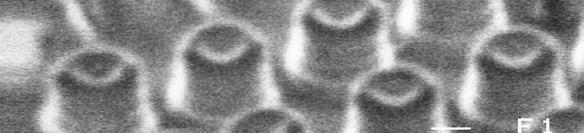
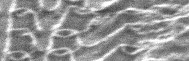
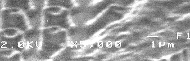
11 Nanoscale Biomechanosensor F δ It is sensible to downsize the microfabricated structures to nanoscale: To enhance the probing sensitivity To enhance the spatial resolution To improve the material compatibility Direct optical measurement is no longer appropriate λ / 2n sin( α)? How to measure the deformation in nanostructures?
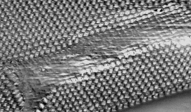
12 SEM of fabricated equally spaced polymeric periodic substrate (PPS) 5 µm 5µm


13 Imaging Interface: Optical Moiré technique * Moiré Fringes: or the moiré effect refers to light/dark bands seen by superimposing two nearly identical arrays of lines and dots. * In most basic form, moiré methods are used to measure displacement fields. Laboratory for Microsystems Technology, Boston University
14 Force Mapping in Vascular Smooth Muscle Cells 0 hr 4 hrs 8 hrs 12 hrs 18 hrs 24 hrs As the VSMCs spread out in DMEM media with serum, the moiré patterns changed from regularly distributed to locally distorted, and further resembled a natural centrifugal pattern, revealing the concentric profile of the traction forces developed on the substrate. Laboratory for Microsystems Technology, Boston University

15 Corresponding Force Map Derived from Moiré Derived cellular traction force mapping * Length and direction of the arrows: the direction and magnitude of the forces derived from the map * Colors: the magnitude of the displacements A 2 12 hrs B hrs * Decrease of traction force with decreasing spreading area * Concentrated at the boarder of the cells, pointing to the nuclei directions * Least traction forces concentrated at the central region of the cells C 24 hrs
 50 40 30 20 10 0 Point 1 Point 2 Point 3 Point 4 Point 5-10 0 4 8 12 16 20 24")

16 Determining Force Evolutions from Moiré Patterns Laboratory for Microsystems Technology, Boston University µm Force (nn) Point 1 Point 2 Point 3 Point 4 Point Culture time (hr) To determine the magnitude of the contraction force developed on adhesion areas from the moiré patterns: * Derived the traction force on five locations * Mapped the evolution of the traction forces over time
17 Conclusions Fabrication Polymer micro- and nanostructures with various aspect ratios Characterization Deep beam model Moiré techniques Measurement and Analysis Micro/nanofabricated polymer based system provides in-vitro cell traction force mapping in the sub-cellullar level Optical moiré approach provides robust and real-time imaging of in-plane cell traction force mapping Such optical moiré system can be readily employed to study migration, morphology, motility and many other cell-substrate mechanical interactions on patterned polymer substrates. Since our approach requires neither the tracking/monitoring nor the visibility of each individual pillar, we anticipate that this method will increasingly find more applications in micro and nano patterned substrates for a variety of mechanics studies in living cells.
18 Acknowledgements NSF CAREER Award Brigham and Women's Hospital, Tufts-New England Medical Center Vanderbilt Medical Center