Patient-Based Cardiovascular Device Simulations: your guide from Bench to Bed. Matthieu De Beule, CEO
|
|
|
- Augustine Dorsey
- 5 years ago
- Views:
Transcription

1 Patient-Based Cardiovascular Device Simulations: your guide from Bench to Bed Matthieu De Beule, CEO FEops, Ghent, Belgium
2 Disclosure Statement of Financial Interest Within the past 12 months, I or my spouse/partner have had a financial interest/arrangement or affiliation with the organization(s) listed below. Affiliation/Financial Relationship Major Stock Shareholder/Equity Ownership/Founder Company FEops FEops


3 How FEops provides insights for excellence Quantify complex anatomy Fatigue modelling Complex balloon modelling Quantify in-vivo loading TAVIguide technology MITRALguide technology

4 Next generation TAVI devices G Manoharan, Royal Victoria, Belfast


5 How to find the optimal balance? PVL reduction Valve sizing Avoid undersizing PPM reduction Valve sizing Avoid oversizing Valve positioning Avoid low implantation Valve positioning Avoid too high implantation


6 New generation TAVI planning 3D computer model of aortic root based on preoperative CT Mechanical behaviour of different tissue regions is incorporated 3D computer model transcatheter aortic valve Mechanical behaviour of stent frame is taken into account Prediction of valve morphology and function post-tavi using physicsbased simulations ADVANTAGES Unique insights can be obtained prior to the actual intervention Optimal device size and position can be selected for each patient FEops TAVIguide TM is not FDA approved / cleared. FEops TAVIguide TM is CE marked, but not all commerically available devices are already included in the current release
7 TAVIguide workflow FEops TAVIguide TM is not FDA approved / cleared. FEops TAVIguide TM is CE marked, but not all commerically available devices are already included in the current release
![Difference (Model - MSCT) [mm]](/docs-images/92/110375228/images/8-1.jpg "TAVIguide predicts frame")
 Mean")

![32 Mean (Model, MSCT) [mm]](/docs-images/92/110375228/images/8-4.jpg "Data from EMC Rotterdam; UZA")
8 Difference (Model - MSCT) [mm] TAVIguide predicts frame morphology MSCT-post Model Dmax at inflow (33 pts) Mean difference +0.6mm; SD 1.1mm Mean (Model, MSCT) [mm] Data from EMC Rotterdam; UZA Antwerp and ICPS Massy
![Difference (Model - MSCT) [mm] Difference(Model -MSCT) [mm] TAVIguide predicts calcium displacement Model prediction MSCT-post Calcium coronary ostia distance (33 pts) Mean difference +1.0mm; SD 2.](/docs-images/92/110375228/images/9-2.jpg "0mm 12 8 4 0-4 -8 Calcium displacement was quantified by measuring the distance from the coronary ostia to the closest calcium nodule -12 0 4 8 12 16 20 Mean (Model, MSCT) [mm] Data from EMC")
9 Difference (Model - MSCT) [mm] Difference(Model -MSCT) [mm] TAVIguide predicts calcium displacement Model prediction MSCT-post Calcium coronary ostia distance (33 pts) Mean difference +1.0mm; SD 2.0mm Calcium displacement was quantified by measuring the distance from the coronary ostia to the closest calcium nodule Mean (Model, MSCT) [mm] Data from EMC Rotterdam; UZA Antwerp and ICPS Massy
![Predicted PVL [ml/s] TAVIguide predicts PVL 40 N=45 p < 0.](/docs-images/92/110375228/images/10-2.jpg "001 (60 pts) N=15 30 20 10 0 0+1 2+3 Sellers score Cut-off: 16 ml/s Sensitivity:")
10 Predicted PVL [ml/s] TAVIguide predicts PVL 40 N=45 p < (60 pts) N= Sellers score Cut-off: 16 ml/s Sensitivity: 0.80 Specificity: 0.80

11 TAVIguide predicts conduction disturbances Automated quantification of contact pressure between frame and LVOT within a specific region. The number of patients in which the contact pressure in the specified region exceeded a threshold was determined. Pressure above threshold Pressure below threshold 40% 82% 60% 18% TAVI-induced LBBB N = 25 LBBB post-tavi No LBBB N = 22 No LBBB post-tavi
 26 mm 29 mm TAVIguide predicts reduction of PVL by more than")
12 TAVIguide CoreValve case Case from Dr Peter de Jaegere (EMC, Rotterdam, The Netherlands) 26 mm 29 mm TAVIguide predicts reduction of PVL by more than 70%


13 TAVIguide Lotus case Case from Dr Lars Sondergaard (Rigshospitalet, Copenhagen, Denmark) 23mm Lotus Valve 25mm Lotus Valve Predicted PVL Pressure above threshold 6 ml/s NO 0 ml/s YES
14 Conclusions The TAVIguide technology (FEops) has been validated restrospectively extensively for the Medtronic CoreValve Frame deformation and calcium displacement (33 pts) Prediction of paravalvular regurgitation (60 pts) Conduction abnormalities (50 pts ongoing) Validation for the Evolut R, Lotus, Sapien XT and Symetis Accurate neo is ongoing Prospective studies are being defined to confirm the potential added value of the TAVIguide technology to find for example the optimum balance to reduce both PVL and PPM
15 How FEops provides insights for excellence Quantify complex anatomy Fatigue modelling Complex balloon modelling Quantify in-vivo loading TAVIguide technology MITRALguide technology


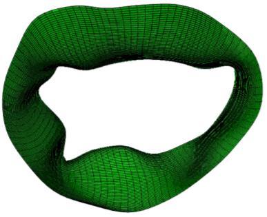
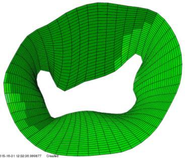
16 New generation TMVR 2 planning 3D computer model of mitral apparatus based on pre-operative CT and/or Echo Mechanical behaviour of leaflets, chords, etc. is incorporated 3D computer model transcatheter mitral valve repair/replacement Mechanical behaviour of device is taken into account Prediction of valve morphology and function post-tmvr 2 using physicsbased simulations ADVANTAGES Unique insights can be obtained prior to the actual intervention Optimal device size and position can be selected for each patient
17 MITRALguide: from 3D echo to model SR DM HK SJM


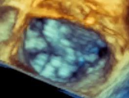
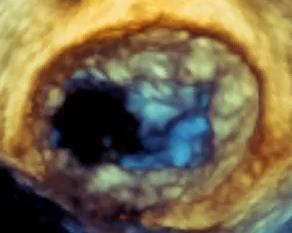


18 MITRALguide: from 3D echo to model SR DM HK SJM

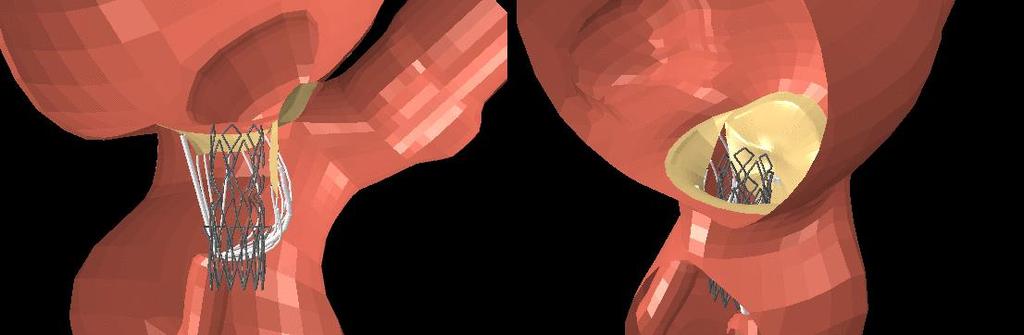
19 MITRALguide - Mitraclip (Abbott)

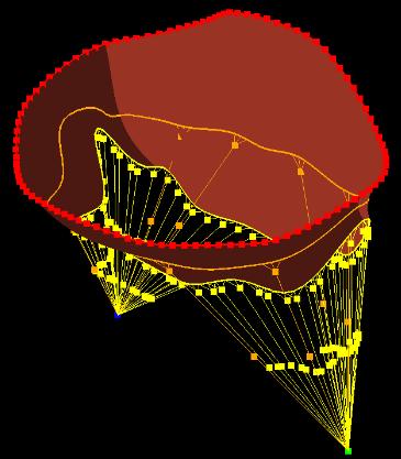
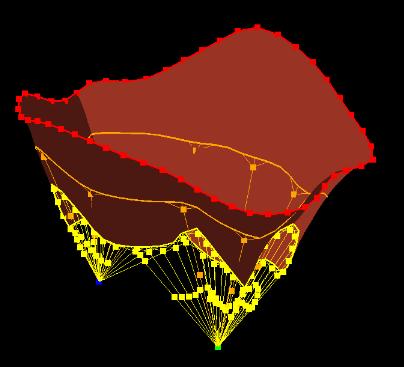
20 MITRALguide - TMVR
21 Conclusions The MITRALguide technology (FEops) can guide R&D Patient selection Procedure planning as it offers unique insights on the device-host interaction (e.g. provide a mental picture of the procedure, quantify forces on the anatomy), complementary to other state-of-the-art experimental bench testing (e.g. 3D printing) based on invivo imaging (CT, echo).
22 Chance only favours the prepared mind - Louis Pasteur FEops, Ghent, Belgium matthieu.debeule@feops.com