Simulation for mass production of automotive composite structural components
|
|
|
- Joy Price
- 5 years ago
- Views:
Transcription
 November")
1 Simulation for mass production of automotive composite structural components Mathilde Chabin, Arthur Camanho (ESI Group) November
!")
2 Lightweight automotive design! To reduce CO2 emissions (environmental awareness and regulation)! Weight-to-power ratio with power limited due to emission regulation! To cut fuel consumption (selling argument)! To increase autonomy Electrification of vehicle results in additional weight (battery) between 250 kg to 350 kg (BMW s MCV, JEC Composites Magazine No 61) è New concept in vehicle architecture and new production processes 2


3 Composites in Automotive Industry Statement! Reduce weight using composites material! Carbon fibers is about 50% lighter than Steel and 30% lighter than Aluminum! Composites are already widely used in automotive industry for non structural components Renault Espace composites Started in 1984 Up to 400 vehicles/day Non structural components Mostly Short fibers SMC process! Industrial wants to extend the use of composites to structural components; Mechanical requirements can only be reached with continuous fiber composites 3
4 ! However! Missing know-how and experience on continuous fiber composites design and manufacturing for automotive applications! Technology transfer from Aeronautics but industry constraints are different!! Specific automotive constraints:! Production time cycle! Process automation! Cost of finished part! Performances (Crash, Safety ) Composites in Automotive Industry Automotive structural components! Recycleability (european regulation ex:reach) 4


: - integration of safety standard of")
5 Composites in Automotive Industry Automotive structural components / Supporting examples! Collaborative program defi composites, LC4 project Low cost Carbon fiber chassis, adapted to automotive production time cycle and safety requirements! BMW backrest in the M3 CSL 6 dies in 2005 with expensive try-outs because of material cost, manufacturing processes Target (First prototype End 2011): - integration of safety standard of constructors chassis/day - Less than 1000 Euros/chassis 2011 target: 2 dies maximum! 5


6 Composites in Automotive Industry Automotive structural components / pain point! Current practices lay on expensive trials RTM B-Pillar: ~ 100kEuros / Die ~ 300 Euros in material per test 6


7 PERFORMANCE MANUFACTURING Buckling Fracture Spotweld rupture Limited interactions so far between Performance and Manufacturing teams Thicknesses Plastic Strain Welding phase Stamping /Welding Crash Stiffness Strength NVH Durability Internal Acoustics Stronger interactions between teams Thicknesses Plastic Strain Welding phase Kinematic hardening Distorsion Stamping / Hotforming SPF / Rolling / Extrusion / Welding Delamination Ply failure Stiffness Strength Sizing of plies Integrated teams Fiber orientations Porosity Stiffness Strength Distorsion architecture STANDARD STEEL HLE / ALUMINUM COMPOSITES Fragmentation Crushing Tape or yarn lay-up Infusion / injection Forming / Thermoforming Sequence of plies 7
8 Agenda of the technical presentations! Manufacturing (10:30-12:30)! Assembly (14:00-15:00)! Physics of materials (15:00-16:00)! Performances (16:00-17:00) 8
9 Composites Manufacturing Simulation for As Built Structural Analysis 9
10 Composites in Automotive Industry Automotive structural components: Material/Manufacturing Fibers Manufacturing technologies Production time cycle Process Automation Material cost Mechanical Performances Filament winding Tape or yarn laying CONTINUOUS Textile: Manual lay-up Pre-pregs: Manual lay-up Textile: -Stamping -Diaphram forming Pre-pregs: TP -Stamping -Diaphram TS forming Manual Manual Automotive structural components AUTOMOTIVE COMPOSITES STRUCTURAL COMPONENTS Expensive raw material but no storage concern and recycling possibility Expensive raw material, storage condition and short life duration SHORT SMC BMC LFT GMT Non structural components 10


 Long fibers")


11 Composites materials and processes Reinforced Thermoplastics Injection molding Thermocompression Press Forming Mechanical Properties / Material costs 2 mm Short fibers unreinforced Mats (GMT) Long fibers Unidirectional Textile Fiber length Design flexibility / production rate Reinforced Thermosets 6 mm 20 mm BMC SMC RTM / Infusion - Vacuum Forming 11
 Long fibers Unidirectional Textile Fiber length Design flexibility / production rate")
12 Short Fiber Injection (1/2) Mechanical Properties / Material costs 2 mm Short fibers unreinforced Mats (GMT) Long fibers Unidirectional Textile Fiber length Design flexibility / production rate 12


13 Short Fibers Injection (2/2)! Driver Airbag container: Polyamide matrix / Glass fiber-30% mass fraction! Modeling:!!! Injection analysis to get fiber orientations Identification of ElastoViscoPlastic Material model with DIGIMAT material model VPS failure analysis using Digimat model Courtesy of TRW Automotive Safety Systems GmbH and DSM

14 LFT: Long Fiber Thermoplastic (1/2) Mechanical Properties / Material costs Short fibers unreinforced Mats (GMT) Long fibers Unidirectional Textile Fiber length Design flexibility / production rate From 8 metallic parts to 1 plastic part LFT decrease weight & cost 14

!")

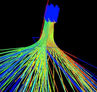
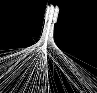
15 LFT: Long Fiber Thermoplastic (2/2) Fiber orientations and damage! Fluid flow with fibers transport! will give final stiffness & strength! Modeling! TP modeled with SPH (meshless method)! Fiber modeled with beam elements! Fiber interactions handled through contact algorithms! Phenomenae not well known!! ESI Ready to engage a cooperative investigations Fiber Damage Velocity Contour


16 Thermoforming (1/7) Mechanical Properties / Material costs 2 mm Short fibers unreinforced Mats (GMT) Long fibers Unidirectional Textile Fiber length Design flexibility / production rate 16


17 ! PAM-FORM can evaluate:! Different forming strategies: Thermoforming simulation using PAM-FORM (2/7)! Stamping, diaphragm (single or double) forming, thermoforming! Clamping conditions, process parameters (tool velocity, temperature, pressure )! Through the prediction of:! Wrinkling! Bridging! Thickness! Optimum flat pattern! Contact pressure! Fiber orientation! Stresses and strains Courtesy: LKT Erlangen-Nürenberg 17


18 Ex1: Wrinkling prediction / forming (3/7)! UD thermoforming / 20 plies / APC2-AS4 (thermoplastic matrix, carbon unidirectional reinforcement) / Quasi-Isotropic lay-up PAM-FORM2G simulation Top and Bottom ply (End view) Top View Wrinkle Smooth surface Bottom View Courtesy: Dassault Aviation Marketing.composites@esi-group.com 18

19 Ex2: Bridging risk prediction (4/7)! Fabric / 6 plies / PPS Matrix PAM-FORM2G simulation Highlights on bridging risks Marketing.composites@esi-group.com Courtesy: Delft University of Technology 19


20 Ex3: Prediction of laminate thickness and thickness per ply (5/7)! Wing box: UD and Fabrics / 8 plies Laminate thickness Ultrasonic measurement versus simulation Top section Thickness per ply determined with PAM-FORM2G Bottom section X=0 480 X=480 Complex clamping conditions determined with PAM-FORM2G Courtesy: Airbus UK Marketing.composites@esi-group.com 20


21 Ex4: Flat pattern optimization (6/7)! J-RIB: 4 plies / thermoforming Upper tool 4 plies Lower tool Initial flat pattern Optimized flat pattern Simulation setup Poor part quality Improved part quality Optimization of flat pattern with PAM-FORM2G Marketing.composites@esi-group.com Courtesy: Airbus UK 21


22 Ex5: Integrated shape and tooling optimization (7/7) 22


23 Liquid Composites Molding (LCM) RTM / Infusion (1/13) Mechanical Properties / Material costs 2 mm Short fibers unreinforced Mats (GMT) Long fibers Unidirectional Textile Fiber length Design flexibility / production rate 23
! Taking into account!")
24 ! PAM-RTM can evaluate and optimize! Injection strategy (RTM, VACUUM INFUSION, VARTM )! Injection pressure and flow rate! Injection gates, vents and vacuum ports location! Molding temperature! Flow media! Through the prediction of! Dry spots! Filling and curing times! Flow front velocity / Fiber washing! Pressure in the mold Liquid Composites Molding Simulation (2/13)! Taking into account! Fiber angle variation (permeability variation) of the preform Marketing.composites@esi-group.com 24
!")


25 Ex1: Resin flow front analysis (3/13)! NCF floor pan injection Filling: 40 % Floor pan injection TECABS: RENAULT Mines Douai 25
")

26 Ex2: Degree of filling, filling and curing time prediction (4/13) Filling time Courtesy: EADS Innovation work, 26
!")
 to minimize:! Dry spots! Filling and curing times! Fiber washing!")

27 Ex3: Complex injection strategy definition (5/13)! Inner liner for hull reinforcement! Very complex part including high shapes (1.2m)! Injection analysis allows determination of injection strategy (injection points/channels and vents location as well as open/closing sequence) to minimize:! Dry spots! Filling and curing times! Fiber washing! Pressure in the mold Initial injection points Secondary injection points/channels Flow front during injection With PAM-RTM Vents location VISIT for complete video presentation Courtesy: PPE & Azimut 27


!")


28 Ex4: Quick estimate of optimum injection strategy (6/13)! Automatic estimate of injection point location and filling time secondes seconde s secondes seconde s 62 secondes 62 seconde 28

29 Ex5: Porosity reduction (7/13) Low resin flow front velocity High resin flow front velocity 29
 Optimized injection flow rate Optimized flow rate 0 1E-04 0 50 100 150")
30 Void content for different Injection strategies Ex5: Porosity reduction (8/13) Void content (a) Constant injection pressure Constant pressure Optimized flow rate profile 7 1E-02 (b) Constant injection flow rate Constant flow rate injection flow rate 1e-7 [m3/s] E-03 Capillary number at flow front (c) Optimized injection flow rate Optimized flow rate 0 1E injection time [sec]
31 Ex5: Effect of Voids on Mechanical Properties (9/13)! E/E 0 =A E *exp(b E /x)! σ/σ 0 =A T *exp(b T /x)! Where x = void content in % Possible reuse of RTM simulation results in part performance assessment Leclerc Jean-Sebastien; Edu Ruiz, Porosity Reduction using Optimized Flow Velocity in Resin Transfer Molding, Elsevier Composites Part A

!")

 :! PAM-FORM")


32 Ex 6: Pre-forming simulation / TECABS (10/13)! TECABS project floor pan (VW, SOTIRA, AIREX, ) :! PAM-FORM helps to Define & Optimize:! The process! The holding system! The plies geometry 32


33 Ex 7: Pre-forming simulation / Eurocopter (11/13) 33
 0-90 FIBRE ORIENTATION")


34 Ex 8: Non Crimp Fabric Draping (12/13) 0-90 FIBRE ORIENTATION Experimental Simulation Simulation results Experimental results Cranfield U. Copyright ESI Group, All rights reserved.

 ±45")


35 Ex 8: Non Crimp Fabric Draping (13/13) ±45 fibre orientation to mould symmetry 0-90 fibre orientation to mould symmetry Cranfield U.

 Long fibers")

36 Distortions (1/2) 2 mm Short fibers unreinforced Mats (GMT) Long fibers Unidirectional Textile Fiber length After Manufacturing 36

.")
37 ! Sources of Distortion! Lay-up! Draping effects! Thermal expansion! Chemical shrinkage! Cure temperature and uniformity of the field! Tool thermal expansion! Simulation Status! Laboratory validation accounting for all these parameters performed in European or French collaborative projects (MAAXIMUS, LCM- SMART).! ESI ready to engage a cooperative investigation Distortion Analysis (2/2) 37
 2 mm")

 Long")
38 Crash worthiness (1/8) 2 mm Unidirectional Assembly Crash Short fibers unreinforced Mats (GMT) Long fibers Textile Fiber length 38

39 Ex1: Preforming Effects on Air Frame Rupture Analysis (2/8)! Simulation assumed uniform stiffness! Stiffness is influenced by draping Discrepancy between experiment and simulation! TSAI-HILL Criterion Courtesy of EADS-M (EC FALCOM project) Maximum 39


40 Ex1: Preforming Effects on Air Frame Failure Analysis (3/8)! Simulation assumed uniform stiffness! Stiffness is influenced by draping Accounting Discrepancy for preforming between leads experiment to the correct and location simulation! of failure! Fibre re-orientation due to forming TSAI-HILL TSAI-HILL Criterion Criterion Maximum Maximum Courtesy of EADS-M (EC FALCOM project) 40

 (J. Bréard)! Micro voids intra-tow!")
41 ! For high performance composites, formation of microvoids inside the fiber tows should be minimized! Macro voids Inter-tow Ex2: Effects of Injection conditions onto Mechanical Performance (4/8) (J. Bréard)! Micro voids intra-tow! Micro-voids are highly related to the resin velocity! Critical impregnation velocity 41


42 Ex2: Influence of Porosities on Stiffness & Strength Lay-up definition Draping and RTM Model Lay-up + material Design Iteration Strength analysis Draping and Porosity effect on mechanical properties 42
43 Benefits of ESI Solution! Help to optimize production time cycle by a better understanding and control of the process! Help to reduce production cost by evaluating new composites manufacturing strategies! Detect and correct manufacturing defects that would impact the structural performances of the part! Allow realistic description of the formed part, enabling a predictive mechanical performance simulation Marketing.composites@esi-group.com 43


44 RAIDS-OUTILS MAPPIC World class projects HIVOCOMP MAPPIC LYCOS Performa nce Material LYCOS FormingHIVOCOMP Assembly Injection/ Infusion Distortion Curing INFUCOMP LCM-SMART MAAXIMUS 44


45 Automotive projects EU projects! EC / TECABS! Floor pan! Link form to crash! FR / MATSIESA2! Thermoplastics forming for dash panels / on-going! Partners: Visteon, Renault, Chomarat! FR / LYCOS 28 Metallic parts 8 Preforms + 5 Foam cores! CFRP Thermoplastics seat structures / on-going! Partners: Faurecia, Rhodia, Activetech, Prodhag, RJP Modelage, Styl monde 45


46 RAID-OUTILS (1/2)! New Textile technology for Stiffeners! Partners: EADS, Hutchinson, CETIM, etc! ESI tasks: Mechanical properties / permeability prediction through simple braiding simulation 46
!")


47 RAID-OUTIL (2/2)! Permeability prediction on a Unit Cell: FPM simulation: Injection in z direction Imposed velocity, viscosity and pressure at borders Braiding tools Kinematics Constraints ΓC 2 Braiding/weaving simulation for accurate geometrical representation ΓC 1 ΓF ΓL Fibers Result: Pressure gradient Darcy s law 47
 thermoset matrix materials 2.")
48 HIVOCOMP! HIVOCOMP EC FP7 Project with CRF Advanced materials enabling HIgh-VOlume road transport applications of lightweight structural COMPosite parts! Objectives! Achieve radical advances in two materials 1. advanced polyurethane (PU) thermoset matrix materials 2. thermoplastic self-reinforced polymer composites incorporating continuous carbon fibre reinforcements (Hybrid/SRC)! Assure that these material innovations can be successfully translated into high-impact industrial applications! Hybrid B-pillar (PU/Hybrid-SRC), composite B-pillar (PU), front structure (PU), side closure (PU), seat frame (Hybrid-SRC) and suitcase (Hybrid-SRC) 48


49 Mappic 3D (1/3) : One- shot Manufacturing on large scale of 3D upgraded automo8ve panels and stiffeners for lightweight thermoplas8c tex8le composite structures Yarns Cutting & 2D fabric Lay up forming Joining Waste Mappic 3D Part two technologies : panels and s1ffeners Reduc1on of cost : 38 % Reduc1o n of 1me produc1on : 25 % :
50 Process simulation to get local porosities (2/3) + compression and temperature Braiding simulation + draping (Thermoplastics filament inside) Intra yarn simulation of thermoplastics diffusion FPM (Local model) of the melted thermoplastic filaments Prediction of intra yarn porosity Local model Numerical experiment Statics Rupture Mapping of properties Inter-yarn diffusion (FPM) Prediction of inter yarn porosity 50


 (h) (d) (i) VPS")
51 Prediction of performance based upon manufacturing (3/3) Braiding simulation Local fiber orientation Local properties Porosities Mapping Battery containers Stiffeners Plastic oil pan (a) (e) (f) (b) (g) (c) (h) (d) (i) VPS Statics, NVH and crash performance


52 Composites partnerships and network! RTM! POLY MONTREAL! ECN! CURING! Cranfield U.! DRAPING! INSA LYON! DISTORTION! SWEREA SICOMP! MECHANICAL PERFORMANCE! IFB! KUL 52

53