Femtosecond micromachining in polymers
|
|
|
- Leslie Bailey
- 5 years ago
- Views:
Transcription
1 Femtosecond micromachining in polymers Prof. Dr Cleber R. Mendonca Daniel S. Corrêa Prakriti Tayalia Dr. Tobias Voss Dr. Tommaso Baldacchini Prof. Dr. Eric Mazur

2 fs-micromachining focus laser beam inside material or on its surface
3 fs-micromachining photon energy < bandgap nonlinear interaction
4 fs-micromachining nonlinear interaction E gap E f = h
5 fs-micromachining nonlinear interaction E gap E f = h multiphoton absorption
6 fs-micromachining it is important to understand the nonlinear interaction, as well as the nonlinear response of organic compounds and polymers
7 fs-micromachining applications: data storage waveguides microfluidics biology Polymers and organic materials
8 Outline Introduction to nonlinear optics fs-micromachining microstructuring MEH-PPV waveguides in azopolymers two-photon polymerization birefringent microstructures fluorescent microstructures biocompatible microstructures
9 Linear optics E rad. << E inter. harmonic oscillator linear response P E

 E ( 2")
10 Nonlinear optics high light intensity E rad. ~ E inter. anharmonic oscillator nonlinear polarization response P ( 1) E ( 2 ) E 2 ( 3 ) E 3...
11 two-photon absorption Third order processes ( 3 ) 2 Abs 0 I
12 two-photon absorption Nonlinear interaction provides spatial confinement of the excitation fs-microfabrication 0 0 I
13 femtosecond pulses Ti:Sapphire lasers 100 fs 50 fs 20 fs Repetition rate 1 KHz 1 ms Energy mj 100 fs 12 ns 86 MHz 100 fs nj

14 femtosecond pulses amplified laser oscillator repetitive cumulative

15 fs-pulses for micromachining polymers Oscillator: 80 MHz, 5 nj heat diffusion time: t diff ~ 1 s cumulative
16 fs-microfabrication linear versus nonlinear absorption 0 0 I

17 fs-microfabrication Nonlinear interaction provides spatial confinement of the excitation 0 0 I
18 two main techniques 1 2 fs-laser micromachining ablation structural modification microfabrication via two-photon polymerization

19 1 fs-laser micromaching Surface Volume

20 Micromachining the conductive polymer MEH-PPV optical microscopy a: 0.07 nj b: 0.14 nj c: 0.34 nj d: 0.68 nj
21 Micromachining the conductive polymer MEH-PPV a 0.3 nj atomic force microscopy b 2.0 nj
22 Micromachining the conductive polymer MEH-PPV

23 Waveguides in azo-polymers H 2 N N N NO 2 DO3 Cl HO H 2 C H 3 C H 2 C H 2 C N N N NO 2 DR13 HO H 2 C H 2 C H 3 C H 2 C N N N NO 2 DR1
24 Waveguides in azo-polymers - photobleaching Absorbance spectrum of PMMA films containing 3.5% by weight of (a) DO3, (b) DR1, and (c) DR13. The dashed lines show the absorbance after micromachining the films.
25 Waveguides in azo-polymers (a) Optical microscope image of the waveguides micromachined (PMMA/DR1) (b) Cross-sectional view of the waveguides

26 waveguides in azo-polymers (c) Output image of the mode profile of nm light coupled through the waveguide

27 photonic devices - wiring optoelectronics circuits of the future 3D wave splitter

28 photonic devices - wiring optoelectronics circuits of the future 3D splitter Bragg grating demultiplexer amplifier interferometer

29 Curved waveguides

30 microstructuring polymer: super hydrophobic surface CCD lens mirror Pockels cell ps-laser objective 0.65 NA sample M.R. Cardoso and C. R. Mendonca


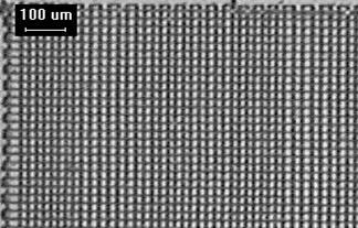

31 microstructuring polymer

32 microstructuring polymer x: 10.0 μm / div. z: 3.0 μm / div. width and depth control
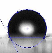
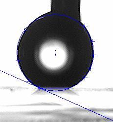


33 microstructuring polymer flat surface θ = 118º microstructured surface θ = 160º

34 2 Two-photon polymerization Monomer + Photoinitiator Polymer light Photoinitiator is excited by two-photon absorption R I 2 PA 2 The polymerization is confined to the focal volume. High spatial resolution
35 Two-photon polymerization
36 Two-photon polymerization even higher spatial resolution
 spacer resin glass (150 micron) Objective 40 x 0.")
37 Two-photon polymerization setup Beam Expansion Scanning Mirror Laser Ti:sapphire laser oscillator 130 fs 800 nm 76 MHz 20 mw CCD camera Objective glass (150 micron) spacer resin glass (150 micron) Objective 40 x 0.65 NA Illumination

38 Two-photon polymerization
39 Resin Preparation Monomers SR499 SR368 reduces the shrinkage upon polymerization gives hardness to the polymeric structure Photoinitiator Lucirin TPO-L


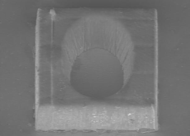
40 Two-photon polymerization 30 µm x 30 µm x 12 µm cube polymer glass

41 Two-photon polymerization After the fabrication, the sample is immersed in ethanol to wash away any unsolidified resin and then dried


42 Microstructures fabricated by two-photon polymerization 50 µ m 50 m 20 µm 20 µm 20 m
43 Doping approach Microstructures containing active compounds monomer monomer Optical active dye Active Polymer
44 Applications of two-photon polymerization Optics and Photonics Doping microstructures with organic molecules and metals fluorescence birefringence conductivity Bio-applications Fabrication using bio-compatible resins to biological applications tissue engineering scaffolds fabrication of microneedle cell study
45 Microstructures properties Applications 1) Optically induced birefringence 2) Emission and conduction 3) Biocompatible microstructure
46 Optically induced birefringence Birefringent microstructures Incorporating the azodye DR13 into the microstructure O 2 N Cl N N N CH3 OH
47 Optically induced birefringence Birefringent microstructures Molecular orientation by excitation with linearly polarized light cis N N ion rate relax R cos 2 N N trans E p dye N N p dye Light E trans cis trans N N Relax N N p dye E After alignment Optically Induced birefringence n y ny n x n x
48 Microstructure with DR13 Birefringent microstructures a Ar+ ion laser irradiation nm one minute intensity of 600 mw/cm 2 20 m
49 Birefringence in the microstructure Birefringent microstructures The sample was placed under an optical microscope between crossed polarizers and its angle was varied with respect to the polarizer angle

50 Birefringent microstructures The structure is visible when the angle between the birefringence axis and the polarizer is an odd multiple of 45 n= 5x10⁻⁵ This birefringence can be completely erased by irradiating the sample with circularly polarized light. Applications: micro-optical switch, micro-optical storage
51 Birefringent microstructures
52 Birefringent microstructures The structure is visible when the angle between the birefringence axis and the polarizer is an odd multiple of 45 n= 5x10⁻⁵ This birefringence can be completely erased by irradiating the sample with circularly polarized light.
53 Emission/Conduction microstructure containing MEH-PPV MEH-PPV Fluorescence Electro Luminescent Conductive
 and ON (c) (d) Emission of the microstructure (black line) and of a film with the same composition (red")
54 microstructure containing MEH-PPV (a) Scanning electron microscopy (b,c) Fluorescence microscopy of the microstructure with the excitation OFF (b) and ON (c) (d) Emission of the microstructure (black line) and of a film with the same composition (red line)

55 microstructure containing MEH-PPV Fluorescent confocal microscopy images in planes separated by 16 m in the pyramidal microstructure.


56 microstructure containing MEH-PPV waveguiding of the microstructure fabricated on porous silica substrate (n= 1.185) Applications: micro-laser; fluorescent microstructures; conductive microstructures


57 microstructures containing chitosan Applications biodegradability biocompatibility bone regeneration drug-delivery bactericide action blood coagulation Microstructures show excellent integrity and good definition
58 3D cell migration studies in micro-scaffolds SEM of the scaffolds 110 µm pore size 52 µm pore size schematic of the scaffold Top view 110, 52, 25, 12 µm pore size Side view 25, 52 µm pore size

59 cell migration 50 m pore size
60 cell migration 50 m pore size after 5 hours c-d: 110, 52, 25 and 12 m
61 Message fs-microfabrication is a great tool for designing polymerbased devices
62 Acknowledgments National Science Foundation Army Research Office FAPESP, CNPq and CAPES
63 Thank you!