Clinical trials with hypo-fractionation for breast conserving therapy (BCT): Shorter overall treatment time Effective radiation treatment
|
|
|
- Paul Townsend
- 5 years ago
- Views:
Transcription


1 AAMD Regional Meeting, March 21st 2015
2 Clinical trials with hypo-fractionation for breast conserving therapy (BCT): Shorter overall treatment time Effective radiation treatment Whelan et al 2013 & Yu et al 2013
3 WHY NOT SBRT for breast? Obstacles for delivering a large dose precisely to a target using EBRT: Limited unobstructed beam angles by Linacs Lack of SBRT system with a suitable immobilization device Whelan et al 2013 & Yu et al 2013


4 Developed by Dr. Cedric Yu, physicist in UMM and President & CEO at Xcision Medical Systems LLC A stereotactic device only for early stage breast cancer Prone position setup 36 Co 60 sources converging at one isocenter Cumulative activity of 4320 Ci (120 Ci/source) 5.31 Gy/min at isocenter Target sizes up to about 6-7 cm in diameter
5 Has not been FDA-approved yet. FDA IDE* approval for a boost trial is in process. Radiation safety testing that FDA required has been performed in UMM under a research license for IDE approval. *IDE - Investigational Device Exemption


6 Installed To be installed


7 Image loader Treatment unit Breast cup immobilization system
 Connected to a")


8 Two layered breast cup Outer cup 3 sizes (small, medium and large) Connected to a vacuum system Includes a built-in CT/MR comparable fiducial wire wrapped helically Inner cup 10 different sizes for each outer cup Silicone flange 3 sizes Vacuum system Yu et al 2013

 is applied to the space between the inner and outer")


9 Immobilization procedures: The inner cup is fit to the breast. The silicone flange is affixed to the patient s chest. The outer cup goes on top of the inner cup. Vacuum (-150mmHg) is applied to the space between the inner and outer cups. A shared coordinate frame system between the immobilization device and patient anatomy is generated. The cup-based coordinate system has a fixed relationship with the couch. Square dots: Detected frame locations Mild suction Inner cup Outer cup Solid line: Actual locations of wire Fiducial wires Yu et al 2013 & Feigenberg et al 2014

 x 83 (height) Weight: 660")


10 Used in CT or MRI rooms for images taken prior to treatment A mobile unit Size: 58 (length) x 43.3 (width) x 83 (height) Weight: 660 lbs Docked to the end of the imaging device table for the patient to stand on in the vertical position and translated horizontally Feigenberg et al 2014
 Weight: approximately 16 tons (floor should take a total weight of 20 tons) Components: Source carrier")
11 Size: 86.3 (length) x 46.5 (width) x 44.1 (height) Weight: approximately 16 tons (floor should take a total weight of 20 tons) Components: Source carrier Collimator Shielding doors Treatment couch Cross section through radiation unit Yu et al 2013
 with 60º longitudinal")
 36 sources")
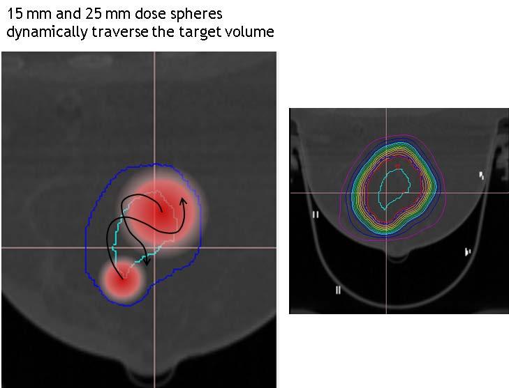
12 Each source 11 mm in height and 3.4 mm in diameter Six columns (6 sources per column) with 60º longitudinal separation in spiral order (a source in each column at every 10º position longitudinally) 36 sources spanning angular section between 18º and 53º, i.e. with 1º latitudinal separation Yu et al 2013 & Mutaf et al 2013
 One blocked The source carrier and the collimator are rotated")
 of 38 cm The isocenter is located 2cm above the top of the")
13 Collimators: Made of tungsten Three selections of collimation: Two open (1.5 cm and 2.5 cm diameters at isocenter) One blocked The source carrier and the collimator are rotated together to create 36 non-coplanar conical arcs all converging at the isocenter. The source to focus distance (SFD) of 38 cm The isocenter is located 2cm above the top of the hemisphere (collimator).


14 Two shielding doors Made of iron and lead Prevent leakage radiation when not treating patient Treatment couch Dynamic motion in three dimensions during beam delivery Capable of tenth-millimeter accuracy


15 A dedicated treatment planning system developed by physicists at Xcision Capabilities: Multimodality image import Stereotactic registration and localization Inverse optimization using dose kernels previously calculated by Monte Carlo simulation for different inner and outer cups Dose calculation and evaluation Treatment export No heterogeneity correction Yu et al 2013 & Feigenberg et al 2014

16
17

18
19 AAPM TG-21 beam calibration A breast phantom made of polyethylene with a density of 0.935g/cm 3 Ion chamber/film/osld Mutaf et al 2013


20 Film insert Film pocket Phantom in couch aperture Viewed from under couch 115mm 70mm 45mm 10mm Ion chamber hole Calibration point Vertical film pocket Couch surface 70mm 140mm

21 coronal sagittal Mutaf et al 2012, Mutaf et al 2013

 (b) z x x y (c) (d)")

22 1.5 cm shot measured vs. calculated relative dose (i) x z x y (ii) (a) (b) (a) (b) z x x y (c) (d) (c) (d) Gamma passing rates >99% (3%/2mm criteria) (e) (e)

")
 z x x y (c) (d)")

23 2.5 cm shot measured vs. calculated relative dose x z x y (i) (ii) (a) (b) (a) (b) z x x y (c) (d) (c) (d) Gamma passing rates >99% (3%/2mm criteria) (e) (e)


24 Treatment plan measured vs. calculated relative dose z x x y (i) (ii) z x x y Gamma passing rates >98% (3%/2mm criteria)
25 Protocol - GCC 1047 IRB approved and patient accrual 21/25 at UMM Spatial reproducibility of markers between two CT scans Internal markers (surgical clips): 1-6 per pt External markers on outer breast cup: 2-6 per pt Breast immobilization 1 st CT scan Simulated plan 10~60 min apart 2 nd CT scan
26 External markers (54): 0.6 ± 0.7 (1σ) mm Breast immobilization is effective only for that portion of breast tissues that falls within the breast cup. Internal markers were classified as those that spatially located inside and outside (towards chest wall) the inner breast cup. Mutaf et al 2014
 mm Outside the breast cup (20 clips): 2.1 ± 2.")
.")
27 CT2 CT1 Internal markers: Inside the breast cup (45 clips): 1.1 ± 0.9 (1σ) mm Outside the breast cup (20 clips): 2.1 ± 2.0 (1σ) mm Therefore, the localization uncertainty of the system for targets within the volume of the breast cup is less than 3.0 mm (95% CL). Mutaf et al 2014 & Feigenberg et al 2014

28 Feigenberg et al 2014

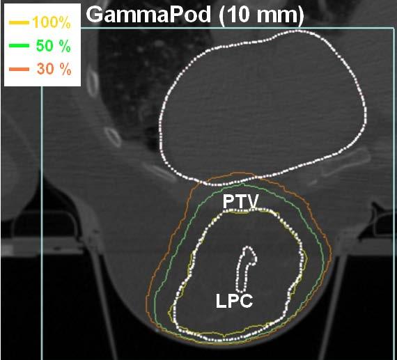
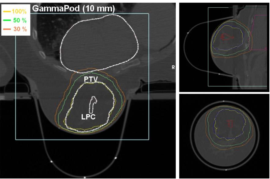
29 The GammaPod TM achieves good conformality and sharper dose profiles due to small collimator openings and short axis-to collimation distance. Linac-based EBRT techniques are limited by the degree of freedom available to the selection of beam angles. This results in undesirable dose spillage outside the target volume and worse conformality. Mutaf et al 2013


30 Mutaf et al 2011
31 Mutaf et al 2011
32 3DCRT IMRT GammaPod Conformity index (Prescription dose volume/ptv) % isodose volume conformity index Ipsilateral breast V 50% 35.4% 30.0% 18.9% Mutaf et al 2011
33 Applicators Single lumen balloon (SLB) (one central dwell position) Multi-lumen balloon (MLB)(up to five catheters with multiple dwell position) Peripheral catheters with a central catheter (SAVI) (6-1) PTV = 1 cm expansion from each applicator surface Dosimetric coverage goals: V95 > 95% of target volume V150 < 50cc V200 < 10cc for SLB and MLB and < 20cc for PCML (SAVI) Oden et al 2013
34 Centrally positioned targets The 6.5 cm target corresponds to the diameter of non-trimmed target for a 4.5 cm balloon (NSABP 2011, p 44). Oden et al 2013

35 Oden et al 2013
36 UMM Dr. Feigenberg UTSW Dr. Rahimi UMM Dr. Nichols UMM Dr. Feigenberg
37 Protocol GCC 1202 IRB approved at UMM but IDE required Accrual - 20 patients PTV = lumpectomy cavity + 1 cm Partial mastectomy 8 Gy in one fraction WBRT Feigenberg et al 2014
38 Xcision Dr. Cedric Yu Dr. Peter Hoban Michelle Crawley UMM Dr. William Regine Dr. Steven Feigenberg Dr. Yildirim Mutaf KU Dr. Parvesh Kumar

39