Abstract. Three dimensional scaffolds play an important role in tissue engineering as a matrix
|
|
|
- Kristian Rogers
- 6 years ago
- Views:
Transcription
1 Abstract CHUNG, SANG WON. Vascular Tissue Engineering Scaffolds from Elastomeric Biodegradable Poly( L -lactide-co-ε-caprolactone) (PLCL) via Melt Spinning and Electrospinning. (Under the direction of Dr. Martin W. King.) Three dimensional scaffolds play an important role in tissue engineering as a matrix that provides the cells with a tissue specific environment and architecture. For cardiovascular applications in particular, the development of elastic scaffolds that can maintain their mechanical integrity while being exposed to cyclic mechanical strains is a necessary criterion. The main objective of this study was to demonstrate the feasibility of fabricating vascular tissue engineering scaffolds via two different approaches, namely; melt spinning and electrospinning. Small diameter tubes were fabricated from two different molecular weights of elastomeric biodegradable poly( L -lactide-co-ε-caprolactone) (PLCL) copolymers. Firstly, 6mm length tubular constructs with the inner diameter of 3/16 inch were produced via melt spinning, and secondly, nanofibrous scaffolds with the inner diameters of 1/8 inch and 3/16 inch were produced via electrospinning. The melt spun tubes produced from the higher molecular weight copolymer contained fibers measuring 253±36μm in diameter, had a porosity of 76.2%, transverse tensile strength of 26.1±1.3MPa, transverse tensile peak strain of 578±17%, and initial transverse tensile elastic modulus of 23.5±0.9MPa. In comparison the electrospun tubes contained nanofibers measuring 540±190nm in diameter, had a porosity of 83.6%, average pore size of 2.08±1.61μm 2. The initial modulus of these 3/16 inch diameter nanofibrous scaffolds (24.6±1.9MPa) was similar to that of the melt spun tubes.
2 However, the peak transverse tensile strength was lower at 17.8±2.0MPa and the peak strain was only 142%. Overall, the mechanical properties of the produced tubes exceeded the transverse tensile values of natural arteries of similar caliber. This is the first report that PLCL copolymers can be melt spun into elastomeric fibers. In addition to spinning the polymer separately into melt spun and electrospun constructs, the novel approach in this study has been to successfully demonstrate that these two techniques can be combined to produce two layered tubular scaffolds containing both melt spun fibers (10-200µm in diameter) and electrospun nanofibers (400nm-2µm in diameter).
3
4 Dedicated to my mother and father ii
5 Biography Sang won Chung was born on January 5th, 1982 in Busan, South Korea. She received her Bachelor of Science degree in Clothing & Textiles in spring 2004 from Seoul National University, South Korea. In pursuit of further studies, she joined North Carolina State University, NC to start her master program in Textile Technology and Management in fall She expects to graduate in May, Upon completion of her master degree, she plans to continue expanding her research interests in biotextiles and biomaterials. iii
6 Acknowledgements First and foremost, I would like to express my sincere gratitude and appreciation to my advisor Dr. Martin W. King for giving me the opportunity to work with him and for providing his continuous guidance and encouragement throughout the entire study. This work would not have been possible without his vast knowledge, experience, enthusiasm, and support. I also appreciate the support given by the other members of my advisory committee, Dr. Hechmi Hamouda and Dr. Stephen Michielsen. I also wish to address a warm thank you to Dr. Michelle Jones for her kindness and guidance in finding my research direction. My special thanks go to Dr. Gerardo A. Montero for his eagerness and assistance which were precious assets for completing many critical phases of this research work. I am also grateful to Dr. Soohyun Kim at Biomaterials Research Center of Korea Institute of Science and Technology (KIST) who provided this novel polymer to us, which actually made this whole study possible. I would also like to offer my appreciation to Dr. Bhupender S. Gupta for letting me use his lab and equipments for research purposes. Many thanks go to Svetlana Verenich for assisting me with the Mini-melter, Birgit Andersen for her guidance on analytical instruments, and Valerie Knowlton for her expert advice on SEM. I would also like to express my appreciation to Hai M. Bui from the machine shop for his promptness. I should also thank Boston Scientific Corporation and College of Textiles for providing financial support during my graduate program. I extend my great appreciation to my friend Nilesh P. Ingle for helping me with the mechanical testing and committing his valuable time to solve all the miscellaneous problems I encountered. I would also like to thank my friend Ajit K. Moghe who has helped me in iv
7 electrospinning process showing deep interest and enthusiasm for this work, always with a big smile. Last but not the least, I would like to express my sincere appreciation, love, and gratitude to my parents, Kihan Chung and Inju Moon who continue to love, encourage and support me through every adventure and challenge. Without their confidence and support in me over the years, I would not have had the opportunities or achievements that I have been so graciously blessed with throughout my life. I also wish to appreciate my only brother Sangchan who can always make me laugh no matter where we are. My gratitude also extends to my great friends who have been such a big support and a source of encouragement during the entire study. Raleigh was less lonely thanks to you all. Sang won Chung Raleigh, NC April, 2006 v
8 Table of Contents LIST OF TABLES...ix LIST OF FIGURES...x 1 INTRODUCTION GOALS AND OBJECTIVES LIMITATIONS REVIEW OF LITERATURE TISSUE ENGINEERING Definition Vascular Tissue Engineering Tissue Engineering Scaffolds Essential Properties Synthetic Biomaterials Conventional Processing Techniques PLCL Synthesis Properties Applications SPINNING METHODS Melt Spinning Electrospinning EXPERIMENTAL MATERIALS POLYMER THERMAL PROPERTIES Differential Scanning Calorimeter (DSC) Thermal Gravimetric Analysis Thermo Haake Mini Lab PRELIMINARY TESTING...44 vi
9 3.3.1 Preparation of Solvent for Electrospinning Conductivity Measurement SCAFFOLDS FABRICATION Melt Spinning of PLCL Electrospinning of PLCL MORPHOLOGY Scanning Electron Microscopy (SEM) Pore Size and Fiber Diameter Measurement by Image Analysis Porosity MECHANICAL PROPERTIES RESULTS AND DISCUSSION POLYMER THERMAL PROPERTIES Differential Scanning Calorimeter (DSC) Thermal Gravimetric Analysis (TGA) Melt Viscosity MELT SPINNING Fabrication of Melt Spun Tubular Scaffolds Morphology Thickness Porosity ELECTROSPINNING Material Variables Effect of Molecular Weight Effect of Solution Concentration Effect of Conductivity Acetic Acid as a Solvent Process Variables Effect of Applied Voltage Effect of Flow Rate Effect of Rotation Speed Fabrication of Electrospun Tubular Scaffolds Morphology Thickness...90 vii
10 4.3.6 Porosity MECHANICAL PROPERTIES Peak Transverse Tensile Stress Peak Transverse Tensile Strain Initial Transverse Tensile Elastic Modulus TUBULAR CONSTRUCTS VIA MELT SPINNING AND ELECTROSPINNING CONCLUSIONS AND RECOMMENDATIONS CONCLUSIONS RECOMMENDATIONS FOR FUTURE WORK REFERENCES APPENDICES A. MELT PROPERTIES OF PLCL B. LOAD-ELONGATION CURVES viii
11 List of Tables Table 2.1-Mechanical properties of the tissue-engineered vascular grafts...19 Table 2.2-Properties of biodegradable synthetic polymers...22 Table 2.3-Composition, molecular weight, and physical state of PLCL copolymers...29 Table 3.1-Experimental design for electrospinning...49 Table 4.1-DSC results of PLCL polymers...56 Table 4.2-TGA results of PLCL copolymers...57 Table 4.3-Melt viscosity of PLCL copolymers...58 Table 4.4-Thickness of melt spun PLCL tubes...62 Table 4.5-Porosity of melt spun PLCL tubes...63 Table 4.6-Experimental conditions for electrospinning tubular constructs...85 Table 4.7-Thickness of electrospun PLCL tubes...91 Table 4.8-Porosity of electrospun PLCL tubes...92 Table 4.9-Peak transverse tensile load (gf) and stress (MPa) for electrospun tubes...94 Table 4.10-Peak transverse tensile load (gf) and stress (MPa) for melt spun tubes...95 Table 4.11-Peak transverse tensile elongation (mm) and strain (%) for electrospun tubes...97 Table 4.12-Peak transverse tensile elongation (mm) and strain (%) for melt spun tubes...98 Table 4.13-Initial transverse tensile elastic modulus (MPa) of electrospun PLCL tubes Table 4.14-Initial transverse tensile elastic modulus (MPa) of melt spun PLCL tubes ix
12 List of Figures Figure 2.1-Tissue engineering paradigm...7 Figure 2.2-Tissue engineering approach to develop organ replacements using cell culture...8 Figure 2.3-Schematic diagram of cell adhesion to ECM...20 Figure 2.4-Biodegradable aliphatic polyesters...24 Figure 2.5-Synthesis of PLCL...28 Figure 2.6-Stress-strain curves of PLCL copolymers and PCL and PLLA homopolymers...29 Figure 2.7-Recovery of PLGA and PLCL scaffolds after different applied tensile strains...30 Figure 2.8-Change of mass of PLCL scaffolds with degradation time in vitro and in vivo...33 Figure 2.9-SEM morphology of VSMCs grown on PLCL scaffolds...34 Figure 2.10-Melt spinning...36 Figure 2.11-Electrospinning...38 Figure 3.1-Thermo Haake MiniLab...43 Figure 3.2-Inside the chamber of MiniLab...43 Figure 3.3-Custom designed wind-up unit...46 Figure 3.4-Schematic drawing of custom-made electrospinning set-up...48 Figure 3.5-Calculation of the volume of the scaffolds Figure 3.6-Mounting frame for tubular structures...54 Figure 4.1-Melt viscosity of PLCL as a function of temperature and residence time...59 Figure 4.2-Melt spun PLCL tubes...60 Figure 4.3-SEM micrographs of melt spun PLCL copolymers...61 Figure 4.4-SEM micrographs showing the effect of molecular weight...64 Figure 4.5-SEM micrograph of electrospun fibers spun from 4% (w/v) PLCL...66 Figure 4.6-SEM micrographs of electrospun fibers spun from 8% (w/v) PLCL...67 Figure 4.7-SEM micrographs of electrospun fibers spun from 12% (w/v) PLCL...67 Figure 4.8-SEM micrographs of electrospun fibers spun from 15% (w/v) PLCL...68 Figure 4.9-SEM micrographs of electrospun fibers spun from 20% (w/v) PLCL...68 Figure 4.10-Different jet formation over time during electrospinning...69 Figure 4.11-Examples of SEM micrographs taken to measure the fiber diameters...70 Figure 4.12-Linear regression of the concentration of PLCL in acetone vs. mean fiber diameter...71 Figure 4.13-SEM micrographs of electrospun fibers showing the effect of conductivity (12%)...72 x
13 Figure 4.14-SEM micrographs of electrospun fibers showing the effect of conductivity (15%)...73 Figure 4.15-Fiber diameter distribution...74 Figure 4.16-Pore size distribution...75 Figure 4.17-SEM micrographs of electrospun fibers showing the effect of acetic acid as a solvent...76 Figure 4.18-Effect of acetic acid as a solvent in jet formation...77 Figure 4.19-SEM micrographs of electrospun fibers showing the effect of applied voltage (12%)...78 Figure 4.20-SEM micrographs of electrospun fibers showing the effect of applied voltage (15%)...79 Figure 4.21-Effect of applied voltage in jet formation...80 Figure 4.22-SEM micrographs of electrospun fibers showing the effect of flow rate (12%)...81 Figure 4.23-SEM micrographs of electrospun fibers showing the effect of flow rate (15%)...81 Figure 4.24-SEM micrographs of electrospun fibers showing the effect of rotation speed...82 Figure 4.25-SEM micrographs of electrospun fibers showing diagonal alignment...83 Figure 4.26-Fast Fourier Transform (FFT) of nanofiber webs...84 Figure 4.27-Electrospun tubular constructs on the collector mandrel...86 Figure 4.28-Electrospun tubular constructs...86 Figure 4.29-SEM micrograph showing the morphology of PLCL nanofibers Figure 4.30-Fiber diameter distribution of PLCL nanofibers...88 Figure 4.31-Pore size distribution of PLCL nanofibers Figure 4.32-Cross-sectional image of an electrospun tube used for thickness measurement...90 Figure 4.33-Peak transverse tensile stress (MPa) of PLCL tubes...96 Figure 4.34-Peak transverse tensile strain (%) for PLCL tubes...99 Figure 4.35-Initial transverse tensile elastic modulus (MPa) for PLCL tubes Figure 4.36-PLCL nanofibers on top of melt spun tubes (70x) Figure 4.37-Alignment of PLCL nanofibers on top of melt spun fibers (200x) Figure 4.38-Nanofibers on top of melt spun fibers from PLCL copolymer (Mw-350,000) xi
14 1 Introduction One of the most severe forms of heart disease is associated with atherosclerosis, a process that causes narrowing of the arteries. Surgical replacement of vessel segments or bypass surgery is the most common intervention for coronary and peripheral atherosclerotic disease with at least 550,000 bypass cases performed per year. 1 An ideal vascular graft should have adequate mechanical strength, blood compatibility, a structure that does not permit hemorrhage through the wall and provide good suture retention. Usually the synthetic polymer vessel is typically made of poly(ethylene terephthalate) (polyester or Dacron) or expanded polytetrafluoroethylene (eptfe Teflon). Although these have been moderately effective for large diameter grafts, on vessels having an inner diameter less than 6mm have yet to be successfully demonstrated clinically despite many years of research efforts using a wider variety of biomaterials. Use of protein coatings and seeding of cultured cells on the inner surfaces of the vessel to increase biocompatibility has potential, but synthetic materials will never be fully acceptable to the body and increase the risk of infection and implantation of native vessels is limited by dimensional and mechanical property mismatches. 2 Given the limitations of these current techniques, the desirability of fully engineered, fully biocompatible blood vessels for implantation is pushing the research area of developing of tissue engineered small diameter blood vessels to be actively investigated. The challenges faced by the approach of tissue engineering for replacing blood vessels are substantial. They include providing a conduit that will have sufficient strength without bursting under increases in blood pressure, a vessel wall that is elastic and can 1
15 withstand cyclic loading, matching compliance of the graft with the adjacent host vessel, and a lining of the lumen that is nonthrombogenic. For tissue engineering, three dimensional scaffolds play an important role as the matrix provides the cells with a tissue specific environment and architecture. The key factors are to create a three dimensional scaffold with suitable degradation rate to meet the requirements of new tissue growth, to supply interconnected pores, to have high porosity to promote cell cell and cell matrix communication, and to have sufficient mechanical stability. Especially for cardiovascular applications, developing scaffolds that can maintain their mechanical integrity while exposing cells to long-term cyclic mechanical strains is necessary to engineer smooth muscle cellular constructs. 3,4 To achieve this, scaffolds should be elastic enough to withstand cyclic mechanical strains without any significant permanent deformation. Also in natural tissues, cells are surrounded by extracellular matrix (ECM), which has structural features ranging from the nanometer scale to the micrometer scale. Thus, replicating the cell s native in vivo environment as closely as possible is a significant factor when designing scaffolds for tissue engineering. This can be achieved by producing nanofiber scaffolds since the inherent property of nanofibers mimic the extracellular matrix of tissues and organs. With recent development in electrospinning, both synthetic and natural polymers can be produced as nanofibers with diameters ranging from tens to hundreds of nanometers with controlled morphology and function. Nanofiber scaffolds are well suited to tissue engineering as the scaffold can be fabricated and shaped to fill anatomical defects, its architecture can be designed to provide the mechanical properties necessary to support cell growth, proliferation, differentiation, and motility, and it can be engineered to provide growth factors, drugs, and genes to stimulate tissue regeneration. 5 2
16 In the design of a scaffold material for the fabrication of engineered tissues, a candidate polymer should possess appropriate mechanical properties, which are suitable for target applications, and its degradation products during implantation should be nontoxic. Over the past years, hydrolyzable and biocompatible copolymers of L -lactide and ε- caprolactone have been of great interest for medical applications. 3,6 Polylactide (PLA) is a crystallizable hard and brittle material, whereas poly(ε-caprolactone) (PCL) is a semi crystalline material with rubbery properties. Copolymers of lactic acid and ε-caprolactone (PLCL) exhibit a range of mechanical properties, depending on their relative composition. 7,8 1.1 Goals and Objectives The goal of this study is to fabricate three dimensional tubular scaffolds by electrospinning and melt spinning elastomeric biodegradable poly( L -lactide-co-εcaprolactone) (PLCL) copolymers. The specific hypothesis behind the study is that by being able to incorporate melt spinning and electrospinning techniques for fabricating the scaffolds, it will be possible to design a mechano-active vascular tissue scaffold which not only has mechanical properties exceeding those of natural arteries but also has an appropriate structure of porosity over 60%. The ultimate transverse tensile strength for human muscular arterial tissue (brachial and popliteal arteries) is in the range of MPa and ultimate elongation is in the range of 65-83%. 9 This will have potential for cardiovascular tissue engineering by facilitating the preparation of bioactive and bioinducible vascular tissues on elastomeric resorbable 3
17 scaffolds. The specific objectives of the study are summarized in the following statements which are designed to provide a comprehensive list of the steps involved from fabrication to evaluation of the novel scaffolds. 1) To characterize the thermal and surface properties of PLCL copolymers. 2) To design an efficient wind-up unit for fabricating melt spun tubes. 3) To fabricate tubular structures via melt spinning of PLCL copolymers. 4) To characterize the morphology, fiber diameter, and porosity of the melt spun scaffolds. 5) To determine the process and material variables for electrospinning PLCL copolymers. 6) To fabricate tubular structures via electrospinning of PLCL copolymers. 7) To characterize the morphology, fiber diameter, pore size distribution, and porosity of the electrospun nanofibrous scaffolds. 8) To characterize the mechanical properties of the melt spun and electrospun PLCL tubes. 9) To demonstrate the feasibility of combining electrospinning and melt spinning of PLCL copolymers within the same tubular construct. It is anticipated that by these specific objectives the ultimate goal of fabricating a novel bioactive vascular tissue scaffold with elastomeric properties, appropriate biodegradability, and good cell adhesion activity will be realized. 4
18 1.2 Limitations Characterization and quantitative analysis of the fabricated scaffolds were difficult to perform since there were no established techniques for evaluating the geometry and distribution of nanofibers. Manual measurements of nanofiber diameters and pore size areas were open to human error even after randomizing the sampling process. Also, due to the limited amount of material available, it was difficult to complete a full design of experiment so as to ensure robust and reliable data. This especially influenced the results of the mechanical testing, which required a substantial number and amount of specimens to minimize the variation between repetitive measurements. Also it limited the number of trials for determining the optimal temperature condition for melt spinning. 5
19 2 Review of Literature 2.1 Tissue Engineering Definition Tissue engineering has grown out of our knowledge of tissue formation and regeneration, and aims to purposefully induce the growth of new functional tissues, rather than just replace diseased or injured tissues with nonviable implantable spare parts. 10 For this reason, tissue engineering has emerged as a promising approach to treat the loss of function of a tissue or organ without the limitations of current therapies. 11 This approach is based on the concept that the dissociated cells will reassemble in vitro into structures that resemble the original tissue when provided with an appropriate environment. In essence, new and functional living tissue is fabricated using living cells, which are usually associated in one way or another with a matrix or scaffolding to guide tissue development. 12 As defined by Langer and Vacanti, tissue engineering is an interdisciplinary field of research that applies the principles of engineering and the life sciences towards the development of biological substitutes that restore, maintain, or improve tissue function. 13 And the goal of tissue engineering is to restore function through the delivery of living elements which become integrated into the patient. 14 This goal, which should lead to the fabrication of new, physiologic, functioning tissue, must involve the combined efforts of cell biologists, engineers, material scientists, mathematicians, geneticists, and clinicians to be successful. 15 In the most frequent paradigm, cells are seeded on a scaffold composed of a synthetic 6
20 polymer or natural material, a tissue is matured in vitro, and the construct is implanted in the appropriate anatomic location as a prosthesis. 1,13,15,16 The first step involves the in vitro formation of a tissue construct by placing the chosen cells (differentiated or undifferentiated) and a biodegradable scaffold in a bioreactor with growth media and a metabolically and mechanically supportive environment, in which the cells proliferate and extracellular matrix is generated. In the second phase, the construct is implanted in the appropriate anatomic location, where remodeling in vivo is intended to regenerate the normal tissue/organ structure and function. 1 The general paradigm of tissue engineering is illustrated in Figure 2.1. Source Phenotype Condition Mechanical stimuli Growth factors Nutrients Cells Construct In vitro maturation in a bioreactor Cell proliferation Cell activation ECM elaboration Scaffolds Mechanical properties Architecture Biological signals Resorption rate Chemistry Engineered Tissue In vivo remodeling Phenotype modulation ECM organization Scaffold degradation Tissue adaptation/growth Figure 2.1-Tissue engineering paradigm 1 7
21 Tissue engineering approaches typically employ exogenous three-dimensional extracellular matrices (ECMs) to engineer new natural tissues from isolated cells. 11 The exogenous ECMs are designed to bring the desired cells into mutual contact in an appropriate three-dimensional environment, to provide mechanical support until the newly formed tissues are structurally stabilized, and also to release specific signals to guide the gene expression of cells forming the tissue. In one approach, cells isolated from a small biopsy and expanded in vitro can be seeded onto a suitable exogenous ECM. They are then either allowed to develop into a new tissue in vitro or transplanted into a patient to create new functional tissue that is structurally integrated within the body. 11,13 Figure 2.2 shows the tissue engineering approach to develop organ replacements using cultured cells. The cells are subsequently seeded onto open, porous, extracellular matrices fabricated from biocompatible, biodegradable polymers and completely natural new tissues will result following polymer degradation. Patient Biopsy Isolated cells Biodegradable Polymer matrix Cells on polymer matrix New tissue Figure 2.2-Tissue engineering approach to develop organ replacements using cell culture 11 8
22 Thus, to restore function or regenerate tissue, a scaffold is necessary that will act as a temporary matrix for cell proliferation and extracellular matrix deposition, with subsequent in-growth until the tissue is totally restored or regenerated. 17 An appropriate scaffold is therefore an essential component for tissue engineering technology. Besides the choice of adequate materials, the macro and micro-structural properties of the materials are of utmost importance. Such properties affect not only cell survival, signaling, growth, propagation and reorganization but also their gene expression, and preservation or differentiation of the phenotype. 18 Tissue engineering represents a new, emerging interdisciplinary field applying a set of tools at the interface of the biomedical and engineering sciences that use either selected living cells or recruited endogenous cells to aid tissue formation or regeneration to restore, maintain, or improve tissue function. 1, Vascular Tissue Engineering Atherosclerotic vascular disease, including peripheral vascular and coronary artery disease, is the major cause of mortality and morbidity in the United States, Europe and other western nations. Each year in the United States, there are approximately 1.4 million procedures performed which require arterial prostheses. 20 Most of these procedures are in small caliber (<6mm diameter) vessels for which synthetic materials are not generally suitable. Current surgical therapy for diseased vessels less than 6mm in diameter involves bypass grafting with autologous arteries or veins, and although the surgical practice is common, vascular grafting has significant limitations and complications. 15,21 Allografts are 9
23 problematic because of the high rate of rejection, and synthetic grafts have been shown to be too thrombogenic when used to bypass arteries less than 6mm in diameter. 22 As a result of these limitations, the development of tissue-engineered blood vessel substitutes has motivated research in the area of cardiovascular biomaterials research for the past 20 years. Several attempts have been made to construct a blood vessel replacement with biological functionality. Early studies to develop a blood vessel substitute focused on the use of bypass grafts engineered from synthetic materials as mentioned above, but for small diameter grafts, the success was minimal due to occlusion and intimal hyperplasia. Failure during the early, acute phase of implantation was mainly due to occlusion derived from thrombus formation, which was initiated by the foreign body response followed by continuous tissue ingrowth. 23 In the chronic phase of implantation, excessive tissue ingrowth, particularly at the anastomosed site (intimal hyperplasia) resulted in thrombus formation and late occlusion. The next advancement was the development of endothelial-cell seeded synthetic grafts by creating a nonthrombogenic interface which was the first example of a tissue engineering approach. 24 However, with limited clinical success, the target has moved towards engineering a blood vessel that exhibits all the functional characteristics of a normal blood vessel. One such example is using collagen to model a blood vessel. In 1986, Weinberg and Bell 25 constructed a layered tissue-vessel consisting of smooth muscle cells and collagen using this approach. This innovative work represents the first modern attempt at engineering cardiovascular tissue. In such a collagen-based approach, the collagen gel acts as an ideal substrate for cell attachment and cell signaling. However, the collagen gel has inherent physical weakness and these constructs were unable to withstand burst strengths for in vivo applications, despite reinforcement with a synthetic material such as a polyester 10
24 (Dacron) mesh. L Heureux et al 26 improved on the mechanical strength of these engineered grafts by culturing mesenchymal cells. The prepared vessel had a burst strength of over 2000 mmhg, which was the first tissue engineered blood vessel, made solely from biological materials, to display a burst strength comparable to that of human vessels. A disadvantage of this approach was that it took minimum of 3 months until the graft was ready to be implanted. Despite numerous efforts to improve the mechanical properties of collagen-based scaffolds, these constructs are still limited by the poor mechanical integrity of the reconstituted collagen gel. 24 Also, naturally derived materials such as collagen must be isolated from human, animal, or plant tissue, and this typically results in high cost and large batch to batch variations. 27 The most typical approach to vascular graft engineering nowadays involves a cell-scaffold-bioreactor system in which exposure to pulsatile mechanical forces is used to improve the properties of the vascular construct. 1 Researchers have long recognized the potential of seeding cells into synthetic biodegradable scaffolds to create various viable tissue analogs, and the cell-seeded polymeric scaffold approach to vascular tissue engineering has recently met with some success. 24 Niklason et al 22 pioneered the approach of combining cells with a biodegradable polymer. They seeded smooth muscle cells from a bovine aorta onto a tubular PGA polymer mesh and cultured the construct in a pulsatile flow bioreactor for 8 weeks. 22 Endothelial cells were then added to the constructs. Histology revealed the formation of elastin and collagen fibers as well as thicker grafts for the pulsed versus the non-pulsed controls. In addition, the pulsed constructs had better rupture strength (greater than 2000 mm Hg) and adequate suture retention strength. When implanted into Yucatan pigs these tissue engineered arteries maintained patency for up to 4 weeks. Langer s group has also reported using a tubular PGA mesh with an inner lining of 11
25 PLGA film to seed aortic smooth muscle and endothelial cells under pulsatile conditions. 20 To enhance the structural stability, Kim and Mooney 28 have used PGA fiber-based matrices bonded with poly-l-lactic acid (PLLA) to resist cellular contractile forces and maintain their predefined structure during the process of smooth muscle tissue development in vitro. Physically bonded PGA matrices have been found to exhibit a 10 to 35 fold increase in compressive modulus over unbonded PGA matrices. Mooney et al 29,30 have also fabricated poly(d,l-lactic-co-glycolic acid) (PLGA) into tubes capable of resisting compressional forces in vitro and in vivo by using solvent casting and particle leaching methods. However, the preliminary results suggest that these devices may need to be mechanically stabilized if they are to maintain their structure in vivo. Thus, the approach of vascular tissue engineering addresses a number of issues which fall into two main categories: ⅰ) the engineering of a construct that meets the necessary functional and mechanical requirements of the specific cell line and ⅱ) the integration of a viable cell construct into a living system with no adverse inflammatory or immune response. Since the vascular wall has a complicated multilayered architecture and unique mechanical properties, there remain several significant challenges before achieving a successful tissue engineered artery Tissue Engineering Scaffolds Three dimensional scaffolds play an important role in tissue engineering as a matrix that provides the cells with a tissue specific environment and architecture. The scaffolds 12
26 should facilitate cell adhesion, promote cell growth, have a wide pore size distribution and high porosity, be mechanically strong, and capable of being formed into desired shapes. 31 It is generally accepted that scaffold material for use in tissue engineering should be biocompatible, biodegradable into nontoxic products and manufacturable. In addition, the scaffold should have a macrostructure that is highly porous and yet initially be mechanically stable. It should have a microstructure that induces cells to attach and regenerate complex tissues, and a molecular structure that releases molecules that induce specific and desired cell responses. 1 The scaffold should resorb once it has served its purpose of providing a template for regenerating tissue and the scaffold degradation rate should be adjustable to match the rate of tissue regeneration as determined by the cell type of interest Essential Properties Porosity and pore size Scaffolds must possess a highly porous structure with an open, fully interconnected geometry and a large surface-to-area volume ratio that will allow cell in-growth and an uniform cell distribution and facilitate the neovascularization of the construct. 11,17 A highly porous scaffold is desirable to allow cell seeding and migration throughout the material. Furthermore, the scaffolds should also exhibit adequate microporosity in order to allow capillary in-growth. Compared to a closed pore structure, an interconnected network of pores enhances the diffusion rates to and from the center of the scaffold and facilitates vascularization, thus improving oxygen and nutrient supply and waste removal. 19 Various 13
27 studies show that high porosity in excess of 90% 32 allows for adequate diffusion during tissue culture and provides sufficient surface area for cell-polymer interactions. However the mechanical strength of a scaffold tends to decrease as the porosity increases. 17,33,34 Thus, for polymeric scaffolds, there may be a conflict between optimizing the porosity and maximizing the mechanical properties. So its overall porosity value should always be balanced with the mechanical needs of the particular tissue that is going to be replaced. In larger scaffolds, high porosity and pore interconnectivity provide suitable hydrodynamic microenvironments with minimal diffusion constraints within a bioreactor that closely resemble natural interstitial fluid conditions in vivo and hence achieve large and well-organized cell communities. 35 Pore size is also critical in both tissue ingrowth and the internal surface area available for cell attachment. The effects of pore size on tissue regeneration has been emphasized by experiments demonstrating optimum pore size of 5µm for neovascularization, 5-15µm for fibroblast ingrowth, 20µm for the ingrowth of hepatocytes, µm for regeneration of adult mammalian skin, and µm for regeneration of bone. 17,36 However, if the pores are too small, then they become occluded by the cells which will prevent cellular penetration, extracellular matrix production, and neovascularization of the inner regions of the scaffold. 17 A further concern is the changes in the effective pore structure in vivo since if the matrices are biodegradable, the average pore size will increase and the interconnectivity of the pore structure will change as well over time. 36 Besides pore size and porosity, the shape and tortuosity of the pores can also affect the rate and extent of tissue ingrowth. 14
28 Surface Properties Surface properties, including both chemical and topographical characteristics, can control and affect cellular adhesion and proliferation. Chemical properties are related to the ability of cells to adhere to a material as well as to protein interactions at the material surface. 17 High internal surface area-to-volume ratios are essential in order to accommodate the number of cells required to replace or restore tissue or organ functions. The surface areato-volume ratio of porous materials depends on the density and average diameter of the pores. 36 If the density of a material such as a fibrous web is high, the porosity should be low. Usually, the density of a fibrous web increases as the diameter of the fiber decreases Mechanical Properties Engineered tissues must possess the appropriate mechanical properties to fulfill their structural role. Therefore, the mechanical properties of the polymer scaffold should be similar to the tissue intended for regeneration. The scaffolds should have sufficient mechanical strength and resistance to deformation to withstand typical hydrostatic pressures and to maintain the space required for cell in-growth and matrix production. 17,18 Particularly, in the reconstruction of hard, load-bearing tissues such as bone and cartilages, the mechanical strength to retain the scaffold s structure after implantation is essential. The biostability of many implants depends on factors such as strength, elasticity, absorption at the material interface and chemical degradation. The degradable scaffold should retain sufficient mechanical strength to manage any in vivo stresses and physiological loadings imposed on 15
29 the engineered construct. 18 For tissue-engineered vascular grafts, hemodynamic competence and suturing characteristics are also critical. 36 It has been reported that by providing a biomimetic in vitro environment, one can accelerate tissue formation and yield a more mature vascular graft for implantation. 2 The rate of the scaffold s degradation must be tuned appropriately so that it retains sufficient structural integrity until the newly grown tissue can replace the scaffold s supporting function Biodegradability and Biocompatibility The biodegradability and biocompatibility of the scaffold will depend mainly on the selection of the polymer. Being biocompatible and degrading into non-toxic products within the desired time frame required for the application is crucial. The biodegradation rate of a polymer depends mainly on the intrinsic properties of the polymer, including the chemical structure, the presence of hydrolytically unstable bonds, the level of hydrophilicity/hydrophobicity, crystalline/amorphous morphology, any glass transition temperatures (Tg), the copolymer ratio, and the molecular weight. 37 Also, the rate can be determined by physical and chemical factors such as the overall porosity, the pore size distribution, the fiber diameter and the ph at the site of implantation. The major class of synthetic biodegradable polymers is the aliphatic polyesters. The degradation of PLA, PGA and PLGA copolymers generally involves random hydrolysis of their ester bonds. 38 The degradation products of PGA, PLLA and PLGA are nontoxic natural metabolites and are eliminated from the body through urine excretion and via the respiratory 16
30 route. An in vitro study with PGA sutures showed that after 49 days, the reported weight loss was around 42% with complete loss of mechanical properties. 38 Poly(lactic acid) (PLA) is more hydrophobic than PGA, so it is more resistant to hydrolytic attack. PLA degrades to form lactic acid which is normally present in the body, and no significant accumulation of degradation products of PLA in vivo has been reported. Poly(caprolactone) (PCL) provides a good permeation for steroids, but its long degradation time (3-5 years) is usually a disadvantage for medical applications such as drug delivery systems. However, when copolymerized with PLA to form a P(LA-co-CL) copolymer the rate of degradation will be faster then for either of the homopolymers. This is due to a decrease in crystallinity and an increase in the rate of water absorption depending on the hydrophilicity of the monomeric units. PGA, PLA and PCL are degraded basically by a non-enzymatic random hydrolytic scission of ester linkages, where the PGA degrades the fastest, PLA slower and PCL even slower. 39 For the purpose of developing biodegradable polymers, Feng et al 40 synthesized the block copolymers of caprolactone and lactide P(LA-co-CL) for the first time in These block copolymers have the advantage over random copolymers that both the permeation rate of steroids and the degradation rate are in between that of their homopolymers, and can be controlled by adjusting the relative composition of the two comonomers. This means that they can be synthesized to yield materials with more rapid degradation rates. Different erosion times may be required of devices being used to engineer different tissues, such as the walls of blood vessels versus intestines. 29 The erosion times of these polymers can be regulated by the ratio of their comonomers. In terms of biocompatibility, scaffolds should be well integrated within the host tissue without provoking an adverse inflammatory or immune response once implanted. 17
31 Some important factors that determine their biocompatibility, such as their chemistry, structure, and morphology, can be affected by polymer synthesis, scaffold processing, and sterilization conditions. Toxic residuals involved in these processes may be leached out of the scaffolds with detrimental effects to the engineered and surrounding tissues Mechano-active Environment For engineering vascular tissues, providing a mechano-active environment in response to pulsatile stress, which results in a compliance similar to that of natural vessels, is important. Arterial tissues are continuously exposed to dynamic mechanical forces such as fluid shear stress, circumferential stress, longitudinal stress, and torsion, which are repeatedly driven by the pulsatile cardiac output. 23 Circumferential stress, sometimes referred to as hoop stress, is the most extensively implemented stimulus for vascular tissue engineering. Most of bioreactors expose tissues to this form of stress. The expansion of this tube, in response to a surge in fluid pressure due to a ventilator or pump, stretches the construct material circumferentially. The pressure change which elicits this expansion is a biomimetic factor, ideally having a frequency, pressure magnitude and waveform identical to the systolic to diastolic cycle of the heart. The result is constructs with organized, circumferentially oriented polymer strands and smooth muscle cells. These constructs are stronger and stiffer than those cultured under static conditions. Among the many factors determining the patency of small-diameter artificial grafts, the compliance mismatch between the native artery and the adjacent artificial grafts has been 18
32 discussed as a major factor of graft failure. The difference in mechanical properties between a native artery and an artificial graft induces a hemodynamical flow disturbance and stress concentration near the anastomosis, thereby enhancing thrombus formation and neointimal hyperplasia. 23 Thus, it is important that the artificial scaffold essentially requires compliance matching with the native arteries as much as possible. Hoerstrup et al 2 have introduced a pulsatile in vitro system to grow seeded PGA vascular constructs anticipating that exposure to physical signals similar to in vivo conditions might result in accelerated tissue maturation and formation of mechanically stable, implantable vascular grafts. It was reported that the mechanical characteristics of the pulsed vascular grafts were more favorable regarding burst strength and suture retention strength (Table 2.1). Table 2.1-Mechanical properties of the tissue-engineered vascular grafts (pulsatile flow vs. static in vitro culture conditions) 2 Time in vitro (days) Burst strength (mmhg) Suture retention (gf) Pulsatile flow Control (static) Pulsatile flow Control (static) Recently, a number of studies have shown that mechanical environment regulates the phenotype and the characteristics of vascular smooth muscle cells in three dimensional as well as in two dimensional culture systems. 3,4,41,42 Kim et al 4 have shown that the appropriate 19
33 combination of mechanical stimuli and polymer scaffolds can enhance the mechanical properties of engineered tissues. Both the short term and long term application of cyclic strain increase proliferation of smooth muscle cells and the expression of collagen and elastin. Mechanical signals conveyed to cells via their adhesion to the surrounding ECM regulate the development of various tissues and the gene expression of many cell types in culture as shown in Figure Gene expression Cytoplasm Cellular cytoskeleton Chemical-signal pathway Cell membrane Integrin Mechanical force Figure 2.3-Schematic diagram of cell adhesion to ECM 11 So in order to engineer functional structural tissues, it is recommended that the correct mechanical stimuli be provided during the process of tissue development via an appropriate synthetic ECM. Engineering vascular smooth muscle cells and/or blood vessels under mechanically active conditions has resulted in enhanced mechanical strength, collagen 20
34 production, or blood vessel patency. 4,22 Smooth muscle cells are a critical component of a number of cardiovascular, gastrointestinal, and urological tissues (e.g., blood vessel, intestine, and bladder) 43 residing in mechanically dynamic environments in vivo. Thus, the development of scaffolds that can maintain their mechanical integrity and transfer the mechanical signals to adhering cells during long-term mechanical strain application is likely to be necessary to engineer smooth muscle under cyclic mechanical strain conditions. 3,41,42 The scaffolds must be elastic and capable of withstanding cyclic mechanical strain without cracking or significant permanent deformation for extended periods of time. Also scaffolds should have surface characteristics capable of transferring the mechanical signals to the cells through specific cellular adhesion. 41 The most appropriate structure and chemistry of scaffolds for engineering tissue under conditions of cyclic strain have not yet been established. However, several scaffolds that exhibit elastic properties have recently been investigated. They include poly(l-lactic acid) bonded to polyglycolide (PGA) fiber based scaffolds 41, type I collagen sponges, poly(glycolide-co-caprolactone) (PGCL) 44, polyurethane 45 and poly(lactide-co-ε-caprolactone) (PLCL) constructs. 3,39,42,46 Natural polymer scaffolds have been studied after cross-linking with chemicals, such as glutaraldehyde, and although such chemical cross-linking increases the elasticity of the scaffolds, these chemicals are potentially cytotoxic to cells. 47,48 Bonding PGA fibers with PLA has been unsuccessful due to the significant permanent deformation that was exhibited under cyclic mechanical strain conditions. 41 Elastomeric PLCL copolymers however, have been proposed as attractive candidates in view of their ability to offer a range of different degradation behaviors. They are believed to have potential as they can extend the degradation period in aqueous conditions compared to PGCL copolymers. 3 21
35 Synthetic Biomaterials Scaffolds can be produced from natural or synthetic biomaterials. Biodegradable synthetic polymers offer a number of advantages over other materials for developing scaffolds in tissue engineering. The key advantages are the ability to tailor mechanical properties and degradation kinetics to suit various applications, and the capacity to be fabricated into various shapes with desired porous and morphological features conducive to tissue in-growth. 38 The greatest disadvantage of synthetic materials is their lack of cellrecognition signals. Therefore synthetic biodegradable polymers that degrade fully into natural metabolites by simple hydrolysis under physiological conditions are the most attractive scaffold materials. 19 One of the major classes of synthetic biodegradable polymers is the class of aliphatic polyesters. The key properties of these polymers are summarized in Table 2.2. Table 2.2-Properties of biodegradable synthetic polymers 36 Polymer Glass Melting Degradation time Tensile transition Elongation Modulus point to lose total mass strength Temperature (%) (GPa) (ºC) (months) (MPa) (ºC) PLGA Amorphous Adjustable PLLA Amorphous PDLLA > PGA > > 6.9 PCL >
36 Polyglycolic acid (PGA), poly(l-lactic acid) (PLLA) and copolymers of poly(lacticco-glycolic acid) (PLGA) are widely used in tissue engineering since these polymers are biodegradable and have gained the approval of the US Food and Drug Administration for human clinical use in a variety of applications. 19 The degradation products of PGA, PLLA and PLGA are nontoxic natural metabolites and are eliminated from the body through urine excretion and respiration. PLLA and PGA exhibit a high degree of crystallinity and degrade relatively slowly, while copolymers of PLLA and PGA (i.e., PLGA) are amorphous and degrade more rapidly. 36 Their degradation rate can be tailored for periods from several weeks to several years by altering the molecular weight and the copolymer ratio of lactic to glycolic acids. 11 Poly(ε-caprolactone) (PCL) is an aliphatic polyester that has also been intensively investigated as a biomaterial. PCL provides a good permeation for steroids, but its long degradation time (3-5 years) is usually a disadvantage for medical applications such as drug delivery systems. Because these polymers are thermoplastics, they can be easily formed into desired shapes by various techniques including molding, extrusion and solvent casting. PLLA is semicrystalline and relatively hard, with a glass transition temperature at about 65ºC and melting temperature at about ºC. PCL is semicrystalline with a glass transition temperature of -60ºC and melting temperature at about 58-64ºC. 36,38 Thus, PCL is always in a rubbery state at a room temperature. Although PLLA, PGA, and PLGA have been widely used in a variety of biomedical applications, their stiff and rigid mechanical properties, their acidic degradation products, and lack of functional groups available for covalent modification limit their usefulness. For these reasons, copolymers of PLA and PCL have been investigated for biomaterial applications. The chemical formula of PLA and PCL is shown in Figure
37 O O O C H CH 3 C n C CH 2 5 O n Poly(lactic acid) (PLA) Poly(ε-caprolactone) (PCL) Figure 2.4-Biodegradable aliphatic polyesters Poly(L-lactide-co-ε-caprolactone) (PLCL) is a copolymer of PCL and PLLA where the characteristics differ widely according to the ratio of ε-cl and LA in the copolymerization. The advantage of this copolymer can be summarized into two reasons. Firstly, when PCL is copolymerized with PLA to form a PLCL copolymer, the rate of degradation becomes faster then for either homopolymers. This is due to a decrease in crystallinity and an increase in the rate of water absorption depending on the hydrophilicity of the monomeric units. For the purpose of developing biodegradable polymers, Feng et al synthesized the block copolymers of ε-caprolactone and lactide for the first time in These block copolymers had the advantage over random copolymers that both the permeation rate of steroids and the degradation rate are in between that of their homopolymers, and can be controlled by adjusting the relative composition of the two comonomers. This means that they can be synthesized to yield materials with more rapid degradation rates. Different erosion times may be required of devices being used to engineer different tissues, such as blood vessel versus intestine. 29 Secondly, because of its highly elastic properties, they have considerable potential for fabricating scaffolds for certain elastic tissues. It has been reported 24
38 that the mechanical properties differ widely according to the ratio of ε-cl and LA in the copolymerization. The range is from weak elastomers to tougher thermoplastics. This will be discussed in more detail in the following section. These synthetic polymers must possess unique properties to serve as an appropriate scaffold specific to the tissue of interest. Many epithelial and connective tissues have a simple macroscopic architecture consisting of a number of thin layers. Bladder, intestine, and blood vessels are composed of layers of smooth muscle cells sandwiched between layers of collagenous vascularized support matrix and an epithelial lining. 16 Such structures can be built by seeding the different cell types sequentially on top of each other Conventional Processing Techniques The next step after selecting the appropriate biodegradable polymer is to develop or choose a suitable processing technique. The processing methodology must not adversely affect the material properties, namely its biocompatibility or chemical properties. 17 Conventional scaffold fabrication techniques include fiber bonding 49, phase separation 45, gas foaming, solvent casting, particulate leaching 3,29,30,50, thermal processing 34, molding from melt and combinations of these techniques. There are methods involving textile fibers including wet spinning 51, electrospinning 8,52-57 and forming nonwoven meshs. 27,32,58 Fiber based scaffolds have been typically produced from PGA or other crystalline polymers. For example, the PGA polymer is formed into fibers (10-15μm in diameter) by polymer extrusion, and textile processing techniques are then applied to crimp, cut and needle these 25
39 fibers to form woven or nonwoven arrays with porosities up to 97%. 32 Since these scaffolds are typically incapable of resisting large compressive loads and tend to collapse in vivo, physically bonding adjacent fibers in the nonwoven structure has been investigated with a view to stabilizing such constructs. One technique for achieving this involves coating the fibers with a secondary polymer, typically PLLA or PLGA, or thermally treating the scaffolds to bond adjacent fibers. This process relies on the thermoplastic behavior of the fibers, and the pattern and extent of bonding is controlled by the processing parameters. 28,49 Although conventionally produced scaffolds hold great promise and have been applied to engineer a variety of tissues with varying degrees of success, most have limitations which restrict their scope of applications. Among the main disadvantages are inconsistent and inflexible processing procedures, the use of toxic organic solvents, the use of porogens and shape limitations. 18,59 Scaffolds produced by solvent casting and particulate leaching cannot guarantee interconnection between the pores because this is dependent on whether the adjacent salt particles were originally in direct contact. Although nonwoven fiber meshes have a large surface area for cell attachment and rapid diffusion of nutrients, they have poor mechanical integrity in the Z (thickness) direction. Excluding gas foaming and molding from melt, conventional scaffold fabrication techniques use organic solvents, like chloroform and methylene chloride, to dissolve the synthetic polymers. The presence of residual organic solvent is the most significant problem facing these techniques due to the risks of cytotoxicity and carcinogenicity it poses to the various cell lines. 26
40 2.2 PLCL Synthesis Over recent years, the biodegradable and biocompatible copolymers of ε-caprolactone (ε-cl) and lactic acid (LA) have been of great interest for medical applications. ε-cl appears to be a suitable comonomer for the preparation of a diversified family of copolymers with mechanical properties ranging from gummy and elastomeric to rigid solids. The elastomeric copolymers have good elongation characteristics, which make them attractive candidates for applications where both elasticity and degradability are required. Crystalline domains consisting of long crystalline L-LA sequences account for the good mechanical strength, biocompatibility, and processability of high molecular weight ε-cl/l-la copolymers and make them suitable for use as strong, degradable biomedical elastomeric materials. 60,61 The preferred method for synthesizing these polymers is almost exclusively ring-opening polymerization. The polymerization of PLCL is carried out by synthesizing L-lactide, ε- caprolactone and 1,6-hexanediol with stannous octoate as the catalyst. Synthesis of the PLCL copolymer is shown in Figure
41 O CH 3 O H 3 C O O O Sn(oct) 2 1,6-hexanediol O L-Lactide (LA) ε-caprolactone (CL) O O O OCHCOCC CH CH2 CH CH CH 2 2C O 2 2 CH 3 CH 3 x y PLCL Figure 2.5-Synthesis of PLCL Properties The option to vary the composition offers a valuable method of tailoring the mechanical properties, biocompatibility, and biodegradability of PLCL copolymers. Since an understanding of the mechanical behavior is essential to the development of new applications, Hiljanen-Vainio et al 7 investigated different copolymers of ε-cl/l-la and ε- CL/D,L-LA in compositions of 80/20, 60/40, and 40/60 by weight percent in the feed. The products were block copolymers with some random structure and, interestingly enough, the physical appearance varied among the compositions. This has been confirmed in another study by Kwon et al, 8 who investigated the copolymer composition on the physical state and mechanical properties of electrospun PLCL fibers (Table 2.3). 28
42 Table 2.3-Composition, molecular weight, and physical state of PLCL copolymers 8 Polymer Monomer feed Copolymer Molecular ratio composition weight LL:CL LL:CL Mn Physical state at 25ºC PLL 100:0 100: Hard solid PLCL 70/30 70:30 74: Hard solid PLCL 50/50 50:50 50: Elastomer PLCL 30/70 30:70 31: Gummy solid PCL 0:100 0: Hard solid According to the study by Hiljanen-Vainio et al, 7 the stress-strain curves of the homopolymers and copolymers were quite different; P(CL80/L-LA20) exhibited yield deformation and ductile failure, P(CL60/L-LA40) exhibited rubber-like behavior with a low elastic modulus, and P(CL40/L-LA60) was both tough and rubber-like with a high elastic modulus (Figure 2.6). 3.0 PLLA P(CL40/L-LA60) PCL Stress / MPa 2.0 P(CL80/L-L20) 1.0 P(CL60/L-LA40) Strain / % Figure 2.6-Stress-strain curves of PLCL copolymers and PCL and PLLA homopolymers 7 29
43 The same group investigated the changes in the mechanical properties taking place as a function of hydrolysis time. The copolymers became stiffer with hydrolysis, while the elongation at break gradually decreased. 60 The mechanism of biodegradation of poly(εcaprolactone), poly(d,l-lactide) and a number of copolymers is qualitatively similar, despite a range of different structures and morphologies. 62 Jeong et al 3 has reported that, unlike PLGA scaffolds or PGA fibers, the PLCL scaffolds kept their original dimensions in the culture media for the first week under cyclic stress, and were finally broken after 2 weeks of exposure. However, when the PLCL scaffolds were implanted in vivo as a tubular construct for 15 weeks, the mass decreased to 81% indicating a very slow rate of degradation. 39 The same group has compared the mechanical properties of PLCL (5:5) and PLGA (7:3) scaffolds and has found that the PLCL exhibits higher elasticity and flexibility. Elastic properties were evaluated by measuring the recovery after stretching as shown in Figure PLCL 60 wt% salt 90 wt% salt 97% recovery at 500% strain 90 Recovery (%) 80 PLGA 90 wt% salt 100% recovery at 100% strain 70 Fracture at 20% strain 60 x Strain (%) Figure 2.7-Recovery of PLGA and PLCL scaffolds after different applied tensile strains 3 30
44 The PLCL scaffold prepared from 60 wt% salt exhibited a recovery of over 97% at applied strains of up to 500%, whereas the PLCL scaffold prepared from 90 wt% salt showed 100% recovery at 100% strain, but only 85% recovery at 200% strain, indicating that as the porosity increases so the recovery decreases. In contrast, the PLGA scaffold prepared from 90 wt% salt had a large deformation and broke at strains as low as 20% Applications Because of their excellent biodegradability and biocompatibility, 63 aliphatic polyesters, such as polyglycolide (PGA), polylactide (PLA), poly(ε-caprolactone) (PCL) and their copolymers, have received great interest in medical applications such as drug delivery systems, sutures, artificial skin, orthopedics, and scaffolds for tissue engineering. PLLA is one of the most intensively studied polymers in orthopedic applications because of its good mechanical properties. However, it is proposed that copolymers of PLLA with PCL may expand its application because it becomes possible to fabricate a family of bioresorbable materials with a wider range of elasticity depending on their composition. The 50/50 PLCL in particular has been preferred as an implant material, due to its superior elastomeric mechanical properties. Grijpma et al 61 has proposed the use of high molecular weight 50/50 PLCL as the biodegradable elastomeric copolymer to replace implantable polyurethanes that contain methylene diphenyl diisocyanate (MDI). Since the degradation products are nontoxic, the use of this aliphatic polyester copolymer is preferable. Hoppen et al 64 have reported constructing a two-ply nerve guide using PLCL as the inner micro porous layer with a pore 31
45 size range of μm. The potential for combining PLCL sponges with collagen, whether by filling or by coating, has been investigated by Taira et al 65 for use as a future dental biomaterial. They examined the cellular reactions when the sponges were implanted subcutaneously in oral tissue. Groot et al 6 compared 50:50 PLCL with polyurethane to examine the possibility of using it for meniscal reconstruction. They were able to show improved adhesion to meniscal tissue. Porous PLCL materials have also been prepared for controlled drug release experiments using a freeze-drying/salt-leaching technique. 66 Inoguchi et al 67 has reported developing a mechano-active vascular scaffold based on a textile tube composed of elastomeric PLCL fabricated by an electrospinning technique. These small-diameter PLCL tubes were made with various wall thicknesses, and their compliance and strain response were determined using a biomimicked circulatory system. Electrospun tubular scaffolds were first introduced by Thien How at the University of Liverpool in 1978, 68 and they have subsequently been modified by his group to improve their mechanical behavior. 67,69 Other studies have investigated structural characteristics, mechanical properties and cell adhesion potential for electrospun PLCL with different compositions. 8,54,56,70 Incorporating bioactive substances within electrospun PLCL fibers has been reported by Kwon et al 70. The group electrospun fiber meshes composed of PLCL with type I collagen and heparin which was found to enhance endothelial cell adhesion and proliferation as well as anticoagulant activity. Jeong et al 3,39,42,46 fabricated PLCL scaffolds by an extrusion/particulate leaching process and investigated the morphology and degradation of the scaffolds in vitro and in vivo. The average pore size was about 150±50μm and the scaffolds indicated a tensile strength of 0.80MPa and an elongation of more than 200%. 46 As the porosity increased, the elastic recovery decreased, and as the pore size 32
46 increased, so the cell adhesion and proliferation increased. Vascular smooth muscle cells (VSMCs) were seeded in order to characterize cell adhesion and proliferation, and the scaffolds were implanted to confirm biocompatibility. This study confirmed that the PLCL scaffolds exhibit complete elastic recovery under cyclic mechanical stress, 3 good biocompatibility for smooth muscle cells, 3,42 and appropriate biodegradability. The PLCL scaffolds degraded slowly, even in the form of a highly porous thin membrane. Porous scaffolds have a larger surface area and interconnected structure so the degradation period would be accelerated compared to films or sheets. The study showed that the Mw decreased gradually to 39% of its initial value after 15 weeks in vivo, compared to 36% after 15 weeks in PBS buffer in vitro. The initial mass fell to 20% after 15 weeks in vivo, compared to only 6% after 15 weeks, but down to 70% after 50 weeks in vitro. 46 It is noticeable that the degradation rate in vivo is faster than that in vitro. This may be due to active enzymes species which are only present in the body (Fig 2.8) In vivo In vitro 60 Mass (%) Degradation time (weeks) Figure 2.8-Change of mass of PLCL scaffolds with degradation time in vitro and in vivo 46 33
47 The same group has also demonstrated that under pulsatile stress cell proliferation was significantly enhanced compared to static culture. 42 This confirms that engineering vascular smooth muscle cells and blood vessels under mechanically active conditions results in enhanced mechanical strength, collagen production, and blood vessel patency. 4,22 1W 5W 8W Control static Pulsatile flow Figure 2.9-SEM morphology of VSMCs grown on PLCL scaffolds 42 34
48 2.3 Spinning Methods In the context of synthetic fiber manufacture, spinning refers to the overall process of polymer extrusion and fiber formation. 71 The fiber forming polymers being solids must be converted into a fluid state for extrusion. The term medical textiles refers to medical products and devices fabricated from textile fibers to filaments, and include products ranging from wound dressings and bandages to high-technology applications such as biotextiles, tissue engineered scaffolds, and vascular implants. 72 Over the past several decades, the use of fibers and textiles in medicine has grown dramatically as new and innovative fibers, structures, and therapies have been developed. 19 All textile-based medical devices are composed of structures fabricated from monofilament, multifilament, or staple fiber yarns formulated from synthetic polymers, natural polymers, or genetically engineered polymers Melt Spinning Melt spinning is relatively economical compared to other spinning methods, but can only be applied to thermoplastic polymers that are stable at temperatures sufficiently above their melting point or softening point to be extruded in the molten state without substantial degradation. The number of holes in the spinneret defines the number of filaments in the yarn being produced. The exit hole is usually circular, giving continuous filaments with a circular cross-section. However, specially profiled filaments and hollow fibers can be produced by specially designed spinneret orifices. Melt spinning is typically used with thermoplastic 35
49 polymers that are not affected by the elevated temperatures required in the melt spinning process. Figure 2.10 is a schematic representation of a typical melt spinning process. Polymer Polymer extruder Metering pump Spinning head Filaments Quench air Convergence guide Take-up spool Figure 2.10-Melt spinning Electrospinning Electrospinning has recently received much attention in healthcare applications especially in biomedical engineering 5,8,52-54,57,69,73-75, providing an alternative approach for the fabrication of unique matrices and scaffolds for tissue engineering. Electrospinning is a 36
50 spinning method that can produce polymer fibers with diameters ranging from several microns down to 100 nm or less. Instead of using air or mechanical forces for extrusion as with conventional fiber spinning process, it relies on the application of a high-voltage electrostatic field between the metallic nozzle of a syringe and a grounded metallic collector. 52 The fibers are typically deposited in the form of a nonwoven web on a target metal collector or a rotating drum through a random deposition process. As the electrostatic charge on the polymer solution in the nozzle accumulates, it creates a repulsive force. At a critical voltage, the repulsive force overcomes the surface tension of the solution and a jet erupts from the tip of the syringe, accelerating toward the collection plate or drum. As the charged jet accelerated toward regions of lower potential, the solvent evaporates while the entanglements of the polymer chains prevent the jet from breaking up resulting in fiber formation. 5 The resulting attenuation produced in the threadline causes the diameters of electrospun fibers to be at least one order of magnitude smaller than those made by conventional melt spinning techniques. The nano scale diameter of the fibers produced and the structure of the nonwoven web resemble certain supramolecular features of extracellular matrix (ECM). 69 Since the fibers, pores, ridges, and grooves in the basement membrane of ECM all have dimensions on the nano scale, this characteristic is especially important for blood vessel tissue engineering scaffold design because the monolayer of endothelial cells grows directly on the basement membrane in native blood vessels. 76 The nonwoven industry generally considers nanofibers as having a diameter of less than one micron, although the National Science Foundation (NSF) defines nano fibers as having at least one dimension of 100 nanometer or less. 77 The small diameter provides a high surface area to volume ratio, and a high length to diameter ratio which are favorable parameters for cell attachment, growth 37
51 and proliferation. It is hypothesized that the large surface area of nanofibers with specific surface chemistry facilitates the attachment of cells and controls their cellular functions. 78 In electrospinning, depositing nanofibers on a static collector plate produces a randomly oriented nonwoven fiber matrix; whereas deposition on a rotating drum or mandrel produces aligned nanofiber matrices. 76,79 Figure 2.11 is a schematic drawing of a typical electrospinning set up. Polymer solution High voltage source Polymer jet Motor Rotating drum Figure 2.11-Electrospinning 38
52 There are various parameter variables that can alter the electrospinning process. The properties of the solution such as conductivity, viscosity, molecular weight, and surface tension can change the results of the spinning process. Controllable processing parameters such as electrical voltage applied on the needle tip, flow rate of the solution, and the distance between the needle tip and the collector can also change the results of the spinning process. Varying one or more of these conditions will result in producing nanofibers from different various polymers, and finding the optimal conditions according to the polymer and the solvent is critical. Successful experiments to produce PLCL nanofibers via electrospinning have used solvents such as acetone, methylene chloride (MC), 1,1,1,3,3,3-hexafluoro-2-propanol (HFIP). Both Mo et al 54 and Xu et al 79 have reported that PLCL scaffolds composed of nanofibers that mimic native ECM, have demonstrated favorable interactions with smooth muscle cells and endothelial cells. Kwon et al 8,67 have successfully produced a compliant mechano-active small-diameter vascular graft via electrospinning. The electrospinning method used to fabricate the scaffolds is simple in its approach, does not involve complex or expensive equipment, and has significant potential for application to the tissue engineering of blood vessels
53 3 Experimental 3.1 Materials Two samples of random poly(l-lactide-co-ε-caprolactone) (PLCL) copolymers were received as solid bulk polymers from the Biomaterials Research Center at the Korea Institute of Science and Technology (KIST). The mole ratio of the two monomers (PLA and PCL) in the PLCL copolymers was 50:50. The molecular weights of the two copolymers were Mn=70,000 and Mw=110,000, and Mn=240,000 and Mw=350,000, respectively. The samples were stored in sealed plastic bags in a vacuumed desiccator. 3.2 Polymer Thermal Properties Differential Scanning Calorimeter (DSC) A Perkin Elmer Diamond DSC-2C differential scanning calorimeter (Boston, MA, USA) was used to identify the glass transition temperature (Tg) and the endothermic peaks of the raw materials. Differential scanning calorimetry measures the amount of energy absorbed or released by a sample as it is heated or cooled, providing quantitative and qualitative data on endothermic (heat absorption) and exothermic (heat evolution) processes. Specimens were cut up to weigh 3 to 5mg which were then crimped and sealed in non-volatile aluminum pans. The specimens were maintained at -50ºC for 1 minute and then heated up to 150ºC at a constant scanning rate of 20ºC per min. The specimens were maintained at 150ºC for 3 40
54 minutes and then cooled down to -50ºC at 100ºC /min to simulate quenching. The specimens were maintained at -50ºC for 3 minutes and then heated up to 150ºC again at a constant scanning rate of 20ºC per minute. The purpose of the quenching process is to remove the previous heat history of the specimen. Calibration of the temperature and exothermic scales was undertaken using a known weight of indium before the tests. The results give the endothermic heat flow (mw) as a function of temperature (ºC). The amount of crystalline material contained in a polymer is defined as the heat of fusion (J/g) and is calculated from the area constructed under the melting peak and above the baseline (Delta H m ). Delta Cp is the change in heat capacity. The degree of crystallinity (DOC) is calculated from the heat of fusion of a measured mass of polymer divided by the heat of fusion of the same polymer in 100% crystalline form. The calculation equation for the DOC is as follows: Heat of fusion for sample Degree of crystallinity (%) = 100% Heat of fusion for 100% crystalline polymer Thermal Gravimetric Analysis A Perkin Elmer Pyris-1 TGA (Boston, MA, USA) thermal gravimetric analyzer was used to test the degradation temperature of each individual raw material. Thermal gravimetric analysis often serves as a preliminary diagnostic tool. It measures the weight loss seen in a 41
55 material as the temperature increases. Usually, stoichiometric, heat stability, and compositional information can be obtained by studying the change in mass as a function of temperature. Also by noting at which temperatures the maximum rate of weight loss occurs, it is possible to identify the composition of an unknown polymer. For our purpose, identifying the degradation temperature was the main objective for this test. Such an apparatus should have the ability to detect oxidation by weight gain and degradation or water evolution by weight loss. Dry specimens weighing 5 to 10mg of were placed in a clean dry pan. The chamber was purged with either nitrogen or air and the sample was heated from 25ºC to 500ºC at a constant rate of 20ºC per minute Thermo Haake Mini Lab Specimens weighing 6 grams were loaded into the twin screw extruder of a Laboratory Thermo Haake Z 4.1 Mini Lab (Figure 3.1 and Figure 3.2). The specimens were heated and forced to flow in the heated circulation system. The melt viscosity was measured using the co-rotating twin screw extruder equipped with a recirculation chamber with pressure sensors. The pressure readings detected by the sensors were used to calculate the melt viscosity over time. The extruder was operated in a closed environment purged with air, at temperatures of 140ºC, 155ºC, 175ºC, and 250ºC and the rotating speeds of the screws were preset at 150rpm, 200rpm, and 300rpm in order to determine the viscosities for different scenarios. Being able to determine the consistency of the viscosity parameters combined with the temperature and screw speed contributed to establishing a viable spinning process. 42
56 Plunger system for feeding Co-rotating screws Figure 3.1-Thermo Haake MiniLab INSIDE THE CHAMBER Co-rotating screws Extruding orifice Figure 3.2-Inside the chamber of MiniLab 43
57 3.3 Preliminary testing Preparation of Solvent for Electrospinning Acetone (Fisher Scientific) was first selected as the solvent for electrospinning PLCL copolymer based on the literature review. Acetone was selected over methylene chloride (MC) and 1,1,1,3,3,3-hexafluoro-2-propanol (HFIP) due to its ease of use and low toxicity. Solutions with polymer concentrations varying from 2%, 4%, 6%, 12% and 15% (w/v) were prepared for both molecular weights. Homogeneous solutions were obtained by slow agitation at room temperature. This was done by using a magnetic stirrer at 300rpm for 3 hours. They were readily dissolved at room temperature for all concentrations and remained clear and stable during storage at room temperature up to 7 days. Acetic acid (Fisher Scientific) was also tried as an alternative solvent for electrospinning. Polymer concentrations were varied from 12% to 15% for the high molecular weight PLCL (Mw- 350,000). The solutions were stirred at 300rpm at a temperature of 30ºC. After about 24 hours, the solutions were clear. Both solvents behaved well with the PLCL polymers and showed potential for electrospinning Conductivity Measurement The conductivity of the prepared solutions was measured using an Orion Model 162 conductivity meter (MA, USA). Standard 1413μS/cm (Cat. No ) was used for calibration. The conductivity probe was cleaned with distilled water before and after use. The 44
58 conductivity of pure acetone and acetone with sodium bromide added was compared. The conductivity was reported in μs/cm. Other salts have been investigated in addition to sodium bromide, such as ammonium acetate. However, the dissolving rate in acetone was too low for further experimental study. 3.4 Scaffolds Fabrication Melt Spinning of PLCL Monofilament fiber samples from both PLCL copolymers (Mw-110,000 and Mw- 350,000) were produced by melt-spinning in a Thermo Haake Z 4.1 Mini Lab under a fixed temperature condition of 155 ºC. The circular orifice for extruding the fibers was 0.25mm in diameter. Six grams of polymer were fed into the chamber and the screws were rotated for 5 minutes before extrusion. The speed of the screws was set to 150rpm based on the preliminary melt viscosity measurements. The custom wind-up unit (Figure 3.3) was designed and built to provide an automated traverse motion for collecting the melt spun monofilament fibers. The speed of the motor for winding was controlled between 100rpm and 200rpm, and the fibers were wound up for approximately 5 minutes on a Teflon FEP tube (ID=1/8 inch, OD=3/16 inch) mounted on a rotating stainless steel rod. 45
59 Traverse mechanism Rotating mandrel Tube formation Figure 3.3-Custom designed wind-up unit Electrospinning of PLCL The custom designed electrospinning apparatus (Figure 3.4) was made up of a highvoltage power supply (Gamma High Voltage Research), an infusion pump (New Era Pump System), a plastic syringe, a stainless steel blunt-ended needle (outer diameter 0.9mm, inner diameter 0.5mm), two kinds of collectors and a grounded cage. For collecting flat samples, a stainless steel disk collector plate (15cm in diameter) was used, and for fabricating tubular constructs, stainless steel rotating mandrel collectors (3/16 inch and 1/8 inch in diameter) were inserted. The rotating mandrel collector was produced in a way so that the stainless 46
60 steel rods could be easily exchanged for convenient sample collection. The grounded cage enabled the fibers to be collected in a more controlled manner by applying a negative voltage. The syringe was horizontally fixed on the infusion pump and the sample solution was fed in at a constant rate through the syringe to the needle tip. The solution was electrostatically drawn from the tip of the needle by applying a high voltage between the collector and the needle. Because of its charge, the ejected solution is drawn toward the collector target as a whipping jet. The distance between the needle tip and the collector was constantly maintained to 15cm. The applied voltage on the needle tip was changed in the range of 12kV to 20kV. The voltage that was applied to the cage was exactly half of that applied to the needle tip. The flow rate of the solution was changed from 0.5ml/h to 1.0ml/h and the rotation speed of the mandrel was also varied between 10, 100, and 200rpm. 200rpm was the upper limit because the limit of the motor speed was 208rpm. 47
61 Polymer Solution Needle Syringe Maintained Flow Rate Whipping jet Cage Collector Plate X kv 1/2X kv HIGH VOLTAGE SUPPLY Disk collector (D=15cm) To fabricate a tubular construct Rotating Mandrel MOTOR Figure 3.4-Schematic drawing of custom-made electrospinning set-up 48
62 Since there was no prior knowledge about electrospinning conditions of this particular PLCL copolymer, the main focus was to find the materials and processing conditions that would successfully fabricate scaffolds. Rather than use a statistical experimental design to determine the effects of both material variables and process variables, the approach was to use single parameter optimization. All other independent parameters were held constant while each of the variables was evaluated. To measure the dependent variables, the morphology of the spun samples was compared by SEM, and limited quantitative analysis was conducted by measuring the fiber diameters and pore sizes manually. The experimental design is presented in Table 3.1. Table 3.1-Experimental design for electrospinning Independent Variables Polymer Molecular Weight (Preliminary testing) Polymer Concentration (w/v, %) Conductivity (μs/cm) Materials variables Mw-350,000 Mw-110,000 4, 8, 12, 15, and 20 With sodium bromide Without sodium bromide Process variables Applied Voltage (kv) Flow Rate 0.5 and 1 (ml/h) Mandrel 20, 100, Rotation Speed and 200 (rpm) Dependent Variables Morphology Fiber diameter Pore size SEM Image analysis Image analysis 49
63 It should be noted that the preliminary trials for evaluating the effect of the molecular weight were performed with a different electrospinning unit which had a vertical orientation. The applied voltage was 50kV and the diameter of the collector plate was 30cm. The distance between the needle tip and the collector was 15cm with a flow rate of 0.1ml/min. After the preliminary trial, the high molecular weight polymer was selected to run the rest of the experiments for evaluating the material and electrospinning process variables. 3.5 Morphology Scanning Electron Microscopy (SEM) In order to determine the morphology and the diameter of the filaments, scaffolds were viewed under a scanning electron microscope (SEM). Images were acquired from a JEOL JSM 5900-LV Scanning Electron Microscope using an accelerating voltage of 15kV and spot size 20. The fabric specimens were mounted on aluminum stubs using conductive carbon tape. Subsequent to mounting, the specimens were coated with gold/palladium using a Hummer 6.2 Sputter Coating System (NC, USA) to obtain an average uniform coating of 100Å thickness. The specimens were coated 5 times, each time depositing a thickness of 20Å at different angles. Multiple random micrographs were obtained at several magnifications. When an image was obtained at a suitable magnification, it was set at the optimal black and gain levels for clarity and was digitally scanned and stored using JEOL Digital Scan Generator V 2.00 software interfaced with the microscope. This system had preset scan 50
64 controls in integrated acquisition mode, a gain factor of 3, resolution of 1280 x 960 and a scan time of 160 seconds Pore Size and Fiber Diameter Measurement by Image Analysis The obtained images of melt spun filaments and electrospun webs were analyzed by measuring the fiber diameters and pore sizes. The measurement was done using Image J which is commercially available NIH image software (Java version). The filaments were analyzed manually, by measuring the diameters and the pores of randomly selected fibers, from an individual image. The randomization process was done by selecting the nearest fiber to the Microsoft Excel generated random coordinates on the plot. Three micrographs at a 5,000x magnification were analyzed for each sample. The scales were calibrated beforehand and the measurements were performed manually by dragging the cursor across the entire width or diameter, perpendicular to the direction of the fiber-axis. For the pore size distribution, the measurements were also done manually by dragging the cursor around the pores on the top layer. Before undertaking these measurements, the contrast and threshold of each image was optimized so as to obtain the pore size distribution of the top layer. The areas of the pores were measured. The data obtained was directly converted to a Microsoft Excel sheet, from which the analyses of the distribution were made. The use of an Automated Capillary Flow Porometer System (PMI) was attempted to obtain the pore size and the porosity data but failed. This was because the electrospun web was not mechanically stable enough to withstand the applied air pressure and also because the pores were too small to be measured. 51
65 3.5.3 Porosity Since the overall porosity of the web could not be measured directly, it was calculated by an indirect approach using the density of the scaffold and the density of the polymer. The porosity was reported in %. Porosity (P) = {1-(d s /d p )} 100 = ms 1- vs dp 100 = ms π (R - r ) l dp 100 Where, d s = density of the scaffold (g/cm 3 ) d p = density of the polymer (g/cm 3 ) m s = mass of the scaffold (g) v s = volume of the scaffold (mm 3 ) R = outer diameter of the tubular scaffold (mm) r = inner diameter of the tubular scaffold (mm) l = length of the scaffold (mm) The density of the polymer (d p ) was found in the literature as the information was not provided by the supplier. The density of the polymer was reported as 1.21g/cm 3 for the 50:50 PLCL polymer. 8 The mass of the specimen was measured after they were produced into 6mm length scaffolds. The volume of the scaffold was calculated as shown in Figure
66 Length=6mm Outer diameter (R) Tubular scaffold Inner diameter (r) Volume (mm 3 ) = π x (R 2 -r 2 ) x length Figure 3.5-Calculation of the volume of the scaffolds 3.6 Mechanical properties Transverse tensile mechanical testing of the melt spun and electrospun tubular structures were performed on an MTS Model 1122 system (NC, USA). For the electrospun tubes, a 10N load cell was used with a crosshead speed of 0.5mm/sec. For the melt spun tubes, a 250N load cell was used with the crosshead speed of 3.5mm/sec. All tests were run to failure. A special frame was designed and used to mount and attach tubular structures to the testing equipment. The frame is shown in Figure 3.6. The frame consisted of two assemblies of steel plates: one for the upper jaw and the other for the lower jaw, ensuring that the tubular fabric specimen was pulled in a uniform fashion. Each assembly had two arms and each arm had a 1mm diameter hole at the end. Two stainless steel pins (one for each assembly) of diameter less than 1mm were inserted into the holes and the tubular fabric sample was mounted in between the two assemblies in such a way that it looped around the pins. The distance between the arms of one assembly was greater than that of the other 53
67 assembly. This allowed the two assemblies to come close to each other, while holding the specimen, so that the smallest specimen could be mounted easily. Upper Jaw Steel Plate Direction of load Fabric Tube Stainless steel needles Needle Lower Jaw Figure 3.6-Mounting frame for tubular structures Ten electrospun 1/8 inch and 3/16 inch diameter tubular specimens were tested to failure. Six specimens of melt spun 3/16 inch diameter tube specimens were also tested to failure. The data were stored digitally by the computer and a plot of load vs. elongation was developed for each specimen. The gauge length for the 1/8 inch (3.18mm) tubes was 4.98mm and for the 3/16 inch (4.76mm) tubes was 7.48mm. The gauge length was calculated using the inner diameter of the tubes making the gauge length different for different size of the 54
68 tubes. The calculation was based on assuming that the width (gauge length) of the tube in the flattened state was half the circumference of the tube using the following equation: Gauge length (mm) = π inner diameter of the tube / 2 The values for peak load (gf) at failure were converted into peak stress (MPa) using the following equation: Peak Stress (MPa) =Force/Area (N/mm 2 ) = load (g) thickness (mm) length (mm) 2 The values of peak elongation at failure (mm) were converted into peak strain (%) using the following equation: Strain (%) = Change in length (mm)/gauge length (mm) 100 Finally, the initial transverse tensile elastic modulus of each specimen was determined by measuring the initial slope of their stress/ strain curve: Initial modulus (MPa) = Stress (MPa)/ Strain Thus, a straight line was drawn on the slope to configure the x, y coordinates at the end of the initial linear portion of the slope. The units of modulus were in MPa, given that the value for strain used was dimensionless. The porosity of the specimens was also considered since the void areas of the pores are not bearing any loads when testing is performed. So for example, if the porosity of the tube is 60%, 0.4 was multiplied to the loaded area when calculating stress and modulus. 55
69 4 Results and Discussion 4.1 Polymer Thermal Properties Differential Scanning Calorimeter (DSC) The glass transition temperatures (T g ) and the endothermic peaks of the PLCL copolymers are listed in Table 4.1. (See the DSC curves in Appendix A). The T g s for both molecular weights were at approximately -28ºC, which is between the values of -60ºC for PCL and 57ºC for PLA, indicating a continuous amorphous phase in both copolymers. Weak endothermic melting peaks were observed during the first scan but they disappeared on the second scan, after rapid cooling. The level of crystallinity for both copolymers was calculated on the basis of the reported enthalpies of melting for 100% crystalline PLLA and PCL, which are 93 and 139J/g respectively. 80 Since the ratio of the copolymer is 50:50, the melting enthalpy for 100% crystalline PCL was selected for inclusion in the calculation. Table 4.1-DSC results of PLCL polymers PLCL Copolymers Mw-110,000 Mw-350,000 Heating Profile T g (ºC) Delta Cp Endothermic Delta H m Crystallinity (J/g*ºC) Peak (ºC) (J/g) (%) First Heat Second Heat N/A N/A N/A First Heat Second Heat N/A N/A N/A 56
70 The percentages of crystallinity are very low suggesting that the weak endothermic peaks are transitory and dependent primarily on prior thermal history. According to Vanhoorne et al 81, the glass transition (T g ) and melting point (T m ) of copolymers depend on the comonomer distribution. For instance, a block copolymer usually exhibits two T g s, in contrast to a random copolymer which exhibits only one. It can be concluded that these two copolymers were synthesized as random structures. This preliminary thermal data provided valuable information for determining the optimal conditions for melt spinning Thermal Gravimetric Analysis (TGA) The TGA results of the degradation temperatures of the copolymers are reported in Table 4.2. The results showed that the PLCL copolymer starts to degrade at approximately 300 (ºC) under both nitrogen and air. Table 4.2-TGA results of PLCL copolymers Initial Degradation Mass Percent Temperature of Most Rapid Mass Percent PLCL Temperature (ºC) (%) Degradation (ºC) (%) Copolymers Air N2 Air N2 Air N2 Air N2 Mw-110, Mw-350, There was little difference for the degradation temperature between both molecular weight polymers, but the different derivative slopes indicated that there might be different 57
71 compositions of the polymer components in the two copolymers with different molecular weights. This may have affected the temperature where the most rapid degradation occurred, since the lower molecular weight PLCL unexpectedly exhibited a higher temperature. This trend was consistent when the polymers were run under both purge gas. All TGA curves are presented in Appendix A Melt Viscosity To determine the optimal temperature for melt spinning, the melt viscosity of both copolymers was measured using a Thermo Haake Mini Lab. The melt viscosity figures after full loading is reported in Table 4.3. The running temperature was selected based on the DSC results. The first run was conducted at 250ºC which was too high. The second run was run at 140ºC which was just above the weak melting peak with a lower screw speed. However, the melt viscosity was in the range of 200Pa.s under these conditions. Several trials were conducted until the optimal condition of 155ºC was found. Table 4.3-Melt viscosity of PLCL copolymers Polymers PLCL (Mw-350,000) PLCL (Mw-110,000) Temperature (ºC) Melt Viscosity After full loading (Pa.s) 5 min after full loading Screw Speed (rpm) Shear Rate (sec -1 )
72 It was observed that as the rotating screw speed was higher, the melt viscosity decreased. This is due to the increase in the shear rate when the screw speed increases. The melt viscosity is in inverse proportion to the shear rate. The residence time of 15 minutes or more for processing these polymers might be too long since it is apparent that both polymer experience some mechanical degradation on account of the high shear rates inside the chamber. Thus, for extrusion or melt spinning, it is suggested that a residence time of less than 5 minutes at 155 C is preferred. It can be concluded that the optimal temperature condition will be in the range of 155ºC since the optimal viscosity range for melt spinning is in the vicinity of Pa.s (Figure 4.1). All the other melt viscosity curves are reported in Appendix A Melt Viscosity [Pa.s] PLCL Med Mw-155C PLCL High Mw-155C Time [min] Figure 4.1-Melt viscosity of PLCL as a function of temperature and residence time 59
. The outer diameter of the Teflon tubes was 3/16 inch therefore producing the scaffolds with an inner diameter of 3/16 inch (4.76mm).")

73 4.2 Melt Spinning PLCL monofilaments were extruded via melt spinning from Thermo Haake MiniLab and were collected in a custom designed wind-up system as a small tube Fabrication of Melt Spun Tubular Scaffolds The extruded monofilaments were wound up for 3-5 minutes on a rotating Teflon mandrel and were removed after collection (Figure 4.2). The outer diameter of the Teflon tubes was 3/16 inch therefore producing the scaffolds with an inner diameter of 3/16 inch (4.76mm). The tubes were cut up in 6mm lengths for scanning electron microscopy (SEM) and mechanical testing. When removed from the Teflon tube, the tubular construct maintained its shape and integrity. The monofilaments were bonded sufficiently to each other not to be concerned about unwinding. The extruded filaments were transparent and solid. Removed from the Teflon tube 6mm ID=3/16 (4.76mm) Figure 4.2-Melt spun PLCL tubes 60
 produced more uniform fibers compared to the low molecular weight PLCL copolymer")
 compared to the low Mw PLCL (30Pa.")


74 4.2.1 Morphology The morphology of the wound up mono filaments is reported in Figure 4.3. The high molecular weight PLCL copolymer (Mw-350,000) produced more uniform fibers compared to the low molecular weight PLCL copolymer (Mw-110,000) under the same spinning conditions. This was due to the difference in melt viscosity, since the high Mw PLCL was more viscous (80Pa.s) compared to the low Mw PLCL (30Pa.s) at 155 C. Mw-350,000 Mw-110,000 Figure 4.3-SEM micrographs of melt spun PLCL copolymers Uniform filaments were produced from the high molecular weight PLCL copolymer with an average diameter of 253±36μm. The filaments were extruded uniformly and their size depended primarily on the wind-up speed. However, with the low molecular PLCL copolymer, the extruded filaments were not uniform due to the low melt viscosity. The filaments had a large range of diameters from 11.8μm to 285μm demonstrating the potential to produce fine fibers. Also the tubes made from low molecular weight PLCL copolymer were less stiff and more flexible than the high molecular weight material. Optimizing the 61
75 wind-up speed following extrusion was the major challenge for the whole process. Controlling the ratio of the speed of extrusion (screw rotation speed) and wind-up speed was crucial. It was observed that when the filaments were extruded and wound up, cold drawing was occurring. It was possible to visually see the necking region as the filaments become drawn and more oriented. The filaments were in a molten state when they were extruded from the mini-melter and when they were collected on the wind-up tube. As they were wound up, they bonded to each other Thickness The thickness of the produced tubes was measured using an optical microscope. Multiple images were chosen from 3 specimens of both molecular weight melt spun PLCL tubes. The thicknesses of the tubes are reported in Table 4.4. Table 4.4-Thickness of melt spun PLCL tubes (mm) Melt spun tubes Thickness (mm) Specimen # Mw-350,000 Mw-110, Mean SD SE CV (%)
76 The scaffolds produced from lower molecular weight PLCL copolymer had more variance in thickness. This is due to lower melt viscosity during extrusion process. The thickness of each tube was used for calculating the peak transverse tensile stress and the initial transverse tensile elastic modulus Porosity The porosity of the melt spun tubes is reported in Table 4.5. The range of porosity values ranged from 75% to 88% for the six specimens measured. The low molecular weight PLCL melt spun tubes had higher porosity compared to the high molecular weight tubes. This could be explained as the lower molecular weight tubes had more variance in filament diameter. Table 4.5-Porosity of melt spun PLCL tubes Melt spun tubes (3/16inch, 6mm) Specimen # Mass (g) ID (mm) OD (mm) Volume (mm 3 ) Density (g/cm 3 ) Calculated Porosity a (%) Mw-350, Mw-110, a Calculated porosity: P = (1-d s /d p ) 100 (d s : density of scaffold, d p : density of PLCL =1.21g/cm 3 ) 8 63

 of the PLCL copolymers in")
 under these")

77 4.3 Electrospinning To determine the best conditions for preparing tubular constructs via electrospinning, first of all various processing variables were evaluated Material Variables Effect of Molecular Weight The preliminary trial to evaluate the effect of molecular weight was done with 4% solutions (w/v) of the PLCL copolymers in acetone. The applied voltage was 45kV and the flow rate was 0.1ml/min. The low molecular weight solution produced only droplets (electrospraying) under these conditions, whereas the high molecular weight solution produced a mixture of fibers and non-uniformed beads. The results are shown in Figure 4.4. Mw-110,000 Mw-350,000 Figure 4.4-SEM micrographs showing the effect of molecular weight 64
78 The results demonstrated that at the same concentration, a higher molecular weight polymer is more capable of producing fibers. But even with the high molecular weight solution, still the fibers were not uniform and the formation of beads meant that the concentration of polymer was not sufficient to produce uniform fibers. The effect of solution concentration is studied in the next section. It has been reported that bead formation is related to the instability of the polymer jet and low viscosity. 73 Especially for low molecular weight polymer solutions, the formation of these droplets is due to the capillary breakup of the spinning jet by surface tension. 73 After viewing the results, only the high molecular weight (Mw-350,000) PLCL copolymer was used to evaluate the remaining variables Effect of Solution Concentration To evaluate the effect of solution concentration, the fiber morphology was compared as well as the average fiber diameters. The flow rate for all concentrations was kept constant at 0.5ml/h, except 20% (w/v) solution which was run at 1ml/h. The 20% polymer solution was too viscous, so the flow rate of 0.5ml/h was not high enough to deposit fibers before the needle became clogged. As the concentration of the polymer increased, more uniform fibers were produced. The morphology is presented in Figure 4.5 to Figure 4.9. At 4% and 8% (w/v) polymer solutions, there was evidence that solvent was left in the collector which didn t evaporate. Although small amount of fibers were produced, beads were still dominant on the collector (Figure 4.5). As the polymer concentration was increased to 12% (w/v), even though there was some evidence of fusing, there was a significant 65

, thicker fibers were produced and an irregular form of deposition occurred (Figure 4.9).")
79 decrease in bead formation and the beads were more integrated into fibers (Figure 4.7). It was also observed that the shape of the beads also changed from spherical to spindle-like with increase in polymer concentration. When the polymer concentration of the solution reached 15% (w/v), the most uniform fibers were collected without any beads (Figure 4.8). But when it reached 20% (w/v), thicker fibers were produced and an irregular form of deposition occurred (Figure 4.9). Also since the solution was too viscose, it was hard to maintain the processing conditions, i.e., the droplet dried out before it could form a jet. It has been reported by Zong et al 82 that at lower concentrations, not only are beads formed, but also they are harder to dry before they reach the collector. The jet breaks up into droplets as a result of surface tension in the case of low viscosity liquids, but for high viscosity liquids the jet does not break up, but travels as a jet to the grounded target. 74 Figure 4.5- SEM micrograph of electrospun fibers spun from 4% (w/v) PLCL 66


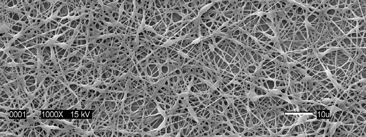
80 Figure 4.6- SEM micrographs of electrospun fibers spun from 8% (w/v) PLCL Figure 4.7- SEM micrographs of electrospun fibers spun from 12% (w/v) PLCL 67


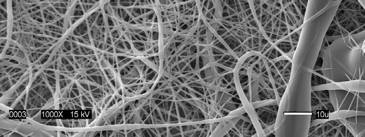
81 Figure 4.8- SEM micrographs of electrospun fibers spun from 15% (w/v) PLCL Figure 4.9- SEM micrographs of electrospun fibers spun from 20% (w/v) PLCL 68


.")
, the jet was most stable at")

82 In addition, the jet formation was observed while increasing the solution concentrations. Even though initially a single jet was formed during the spinning process, after time the jet was diverged into multi directions. For all concentrations, clogging occurred since acetone was evaporating rapidly from the tip of the needle (Figure 4.10). Even though the best fibers were produced at 15% (w/v), the jet was most stable at 20% (w/v) concentration. 8% 1ml/h 14kV 12% 1ml/h 14kV 15% 1ml/h 14kV 20% 1ml/h 14kV Figure Different jet formation over time during electrospinning 69
 polymer concentrations under the same conditions")
 polymer concentration, since there was still some form of spindle-like beads, only")

 concentration of PLCL copolymer in acetone.")
 concentration, the mean diameter drop to 400±150nm.")

83 Mean diameters were compared between the samples that actually produced fibers with minimal beads. Thus, fibers produced from 12%, 15%, and 20% (w/v) polymer concentrations under the same conditions (flow rate of 1ml/h) were compared. For 12% (w/v) polymer concentration, since there was still some form of spindle-like beads, only the diameters of the fibers without beads were chosen to be measured. Figure 4.11 shows an example of the SEM images taken to measure the fiber diameters. 12% 15% 20% Figure 4.11-Examples of SEM micrographs taken to measure the fiber diameters The results showed peak fiber diameters of 760±390nm for the 20% (w/v) concentration of PLCL copolymer in acetone. With a drop in concentration to 15% (w/v), the mean fiber diameter drop to 580±200nm and for 12% (w/v) concentration, the mean diameter drop to 400±150nm. A curve fit of these data could be used to predict the concentration needed to produce a desired fiber diameter within the concentration range that is capable of being spun. A strong linear relationship between the fiber diameter and concentration was observed as presented in Figure The error bars indicate the standard error of the data 70
84 obtained. There was a significant dependence (R 2 =0.9763) of fiber diameter on concentration. This confirms the results from previous studies. 74, y = x R 2 = Mean fiber diameter (nm) Concentration (w/v,%) Figure Linear regression of the concentration of PLCL in acetone vs. mean fiber diameter (nm) Drastic morphological changes were found when the concentration of the polymer solution was changed. Compared to the other variables to be reported in the following sections, concentration and the corresponding viscosity was one of the most effective variables to control the fiber morphology. 71


 polymer concentrations.")
 polymer concentration by adding salt, the diameter of the fibers became smaller.")
85 Effect of Conductivity Using salt was first suggested to stabilize the jet and to reduce the beads formation. To stabilize the jet, the main goal was to increase the conductivity of the solution. For comparison, the conductivity was measured for pure acetone and then with sodium bromide added into the solution. Even though sodium bromide didn t dissolve completely in acetone, a small fraction affected the conductivity of the solution. Before adding salt, the conductivity of acetone was only 1.3µs/cm, whereas after adding sodium bromide it increased to 165µs/cm. The morphology was evaluated with 12% and 15% (w/v) polymer concentrations. By adding salt at 12% (w/v) concentration, there was no improvement in fiber formation but increased fusing. However at 15% (w/v) polymer concentration by adding salt, the diameter of the fibers became smaller. The morphology is shown in Figure 4.13 and Without sodium bromide With sodium bromide Figure SEM micrographs of electrospun fibers showing the effect of conductivity with 12% (w/v) polymer concentration 72


86 Without sodium bromide With sodium bromide Figure 4.14-SEM micrographs of electrospun fibers showing the effect of conductivity with 15% (w/v) polymer concentration It has been reported that the addition of salt results in a higher charge density on the surface of the ejected jet during spinning, thus higher electric charge is carried by the electrospun jet. 82 As the charges carried by the jet increase, higher elongation forces are imposed to the jet under the electrical field. So as the charge density increases, the diameter of the final fibers becomes substantially smaller. 73
87 The average fiber diameter as well as pore size were compared for the 15% (w/v) concentrations. The diameter distribution of nanofibers produced from 15% (w/v) polymer concentration is reported in Figure The mean diameter of the fibers without adding salt was 540±190nm, but after adding sodium bromide the size was reduced to 450±160nm. The distribution shows an evident shift in the average diameter range. 35 Mean 542±189nm 30 Mean 453±163nm 25 Frequency % PLCL 15% PLCL + Sodium Bromide Fiber diameter (nm) Figure 4.15-Fiber diameter distribution 74
88 However, there were no significant changes in the pore size (area) of the two nanofibrous webs. The pore area is reported in μm 2. Since the shapes of the pores were all different varying from circular to triangular, no attempt was made to calculate the average pore diameter. The pore size distribution is reported in Figure Mean pore area 2.08±1.611 µm2 30 Mean pore area 2.132±1.885 µm2 25 Frequency % PLCL 15% PLCL + Sodium Bromide Pore size (area/µm 2 ) Figure 4.16-Pore size distribution 75


89 Acetic Acid as a Solvent Acetic acid was suggested as an alternative solvent since it has been successfully used for electrospinning PCL. Polymer concentrations of 8%, 12%, 15% and 20% (w/v) were evaluated. A lower accelerating voltage of 10kV was applied with a constant flow rate of 0.5ml/h. Unfortunately, there were no uniform fibers formed at any of the concentrations as shown in Figure It was therefore concluded that acetic acid is not a suitable solvent for electrospinning PLCL copolymer. 8% 12% 15% 20% Figure SEM micrographs of electrospun fibers showing the effect of acetic acid as a solvent 76
 concentration.")
90 As the polymer concentration increased, it was possible to observe the changes in bead morphology as in the case of using acetone as the solvent. The spherical shape changed into a spindle-like shape as the concentration increased and irregular fibers started to form at 20% (w/v) concentration. There seem to be a conductivity problem occurring in the process since no fibers were being produced at the higher concentration. Surprisingly, the initial jet was very stable compared to using acetone as a solvent even though it didn t produce any form of fibers (Figure 4.18). Since acetic acid is not as volatile as acetone, there were no significant clogging issues as observed with acetone. 15% (w/v) 20% (w/v) Figure 4.18-Effect of acetic acid as a solvent in jet formation It has been reported that using different solvents will affect the diameter of the fibers produced by electrospinning. Kwon et al 8 have shown different sizes of fibers produced from PLCL copolymer by using methylene chloride (MC) and 1,1,1,3,3,3-hexafluoro-2-propanol (HFIP) as a solvent. With MC, bigger fibers were produced (mean diameter of 7μm) compared to using HFIP (mean diameter of μm). 77
 was used.")

91 4.3.2 Process Variables Effect of Applied Voltage The nanofibrous webs which were spun at different applied voltages are compared in Figure The same solution with a polymer concentration of 12% (w/v) was used. It is noticeable that with the increase in kv, the beads were reduced significantly, and the average diameter increased. The mean diameter of the fibers produced at 20kV was 620±240nm, whereas at 12kV, it was only 400±150nm. 12kv 20kv Figure 4.19-SEM micrographs of electrospun fibers showing the effect of applied voltage (12% (w/v), 1ml/h)) When the polymer concentration of the solution was increased to 15%, the diameter of the fibers also increased without showing any significant improvement in fiber production 78
, 0.")

92 (Figure 4.20). In general, a higher applied voltage ejects more fluid in the jet, resulting in large diameter fibers. 14kv 20kv Figure 4.20-SEM micrographs of electrospun fibers showing the effect of applied voltage (15% (w/v), 0.5ml/h)) The only mechanism of charge transport in electrospinning is due to the flow of polymer from the tip to the target since the electric current caused by ionic conduction of the polymer solution is usually assumed small enough to be negligible. 74 Thus, an increase in the electrospinning current generally reflects an increase in the mass flow rate from the capillary tip to the grounded target when all other variables (such as conductivity and the flow rate of the solution to the capillary tip) are held constant. Figure 4.21 shows the different jet formation with a change in applied voltage. The way in which the polymer solution was released from the needle tip is clearly different due to 79

93 the difference in charge. When the applied voltage is increased, the jet velocity increases and the solution is removed from the tip more quickly. 12kV 20kV Figure 4.21-Effect of applied voltage in jet formation Effect of Flow Rate Flow rate was altered from 0.5ml/h to 1.0ml/h for comparison in morphology. It was found that with 12% (w/v) concentration solution, the lower the solution feeding rate, the more fibers with spindle-like beads were formed. The morphology is reported in Figure As the flow rate increases, the fibers showed more irregularity and non-uniformity. This trend was consistent with an increase in polymer concentration as reported in Figure As the solution flow rate increased, the size of the fibers increased with higher irregularity. 80


 polymer concentration 0.")

94 This is because with higher feeding rate, the droplet suspended at the end of the needle becomes larger, and the solution jet can carry the fluid away with a faster velocity ml/h 1ml/h Figure SEM micrographs of electrospun fibers showing the effect of flow rate with 12% (w/v) polymer concentration 0.5ml/h 1ml/h Figure SEM micrographs of electrospun fibers showing the effect of flow rate with 15% (w/v) polymer concentration 81


95 Effect of Rotation Speed To investigate the alignment of the fibers according to the rotation speed, the mandrel speed was altered from 20, 100, and 200 rpm while collecting the fibers. From the optimal parameters based on the above results, a 15% (w/v) solution concentration was used to electrospin at a 0.5ml/h flow rate and an applied voltage of 14kV. Up to 100 rpm, the fibers were randomly collected without showing any directional alignment. But at 200rpm, it was possible to observe diagonal alignment. The results are reported in Figure Original 20 rpm 100 rpm 200 rpm Figure SEM micrographs of electrospun fibers showing the effect of rotation speed 82

. 0 rpm 200 rpm Figure 4.")


96 It has been previously reported that the rotating speed of the mandrel has to be at least 1000 rpm to observe a change in fiber alignment. 83 So it was anticipated that our rotation speed was too low for a thorough investigation. However, our unexpected results demonstrate that even at the limited speed of rotation of 200 rpm, nanofibrous webs were produced consisting of fibers that were aligned in a diagonal direction (Figure 4.25). 0 rpm 200 rpm Figure SEM micrographs of electrospun fibers showing diagonal alignment This diagonal alignment was confirmed by Fast Fourier Transform (FFT) which is composed of an image of spatial details in the form of brightness transitions. These spatial frequencies are related to the orientation of the fibers and in this technique, the intensity spectra of the pixels in the image are decomposed into a frequency domain with appropriate magnitude and phase values. 84 This helps to determine the rate at which intensity transition occurs in a given direction in the image. So, if the fibers are oriented in a given direction, the spatial frequencies in that direction will be low and the spatial frequencies in the 83
97 perpendicular direction will be high and this is used to determine the fiber orientation distribution. As shown in Figure 4.26, since the web collected on the rotating mandrel was aligned in a diagonal direction, the FFT showed an evidence of a line in the perpendicular direction. Random Aligned Figure 4.26-Fast Fourier Transform (FFT) of nanofiber webs The application of aligned nanofibers in tissue engineering is to control cell orientation. It was found that cells cultured on electrospun fiber scaffolds tend to proliferate in the direction of the alignment of the electrospun fibers. 79 For example, in native blood vessels the shear stress caused by blood flow can orient the shape of endothelial cells in the direction of blood flow, whereas in the wall of blood vessels smooth muscle cells are concentrically lined around each blood cell. 76 Therefore, fibers that are well aligned in the circumferential direction to form a tube would find various applications in fabricating blood vessel scaffolds. 84
98 4.3.3 Fabrication of Electrospun Tubular Scaffolds Based on the results above, the recommended functional parameter conditions to produce electrospun tubular construct with PLCL copolymer were as follows (Table 4.6). Table 4.6-Experimental conditions for electrospinning tubular constructs Functional parameters for fabricating electrospun tubes Polymer concentration Applied voltage Flow rate Distance between the needle and the collector Mandrel rotation speed 15% (w/v) 14 kv 0.5 ml/h 15 cm 100 rpm Two sizes of tubular constructs were produced based on the parameters above. The inner diameters of the tubes were 3/16 inch (4.8mm) and 1/8 inch (3.2mm). The fibers were collected on the metal rod for approximately 5-15 minutes. The electrospun tubes on the metal rod before they are removed are shown in Figure After the tubular structures were produced, they were removed from the metal mandrels and cut into small pieces of 6mm length using a cutter blade as presented in Figure The appearance of the electrospun tubes was white and paper thin, but film-like. The main challenge was removing the tubular web from the collector without damaging it. When the tubes were removed from the metal mandrel, they maintained both their tubular shape and their mechanical integrity. 85
 Figure 4.")

99 6mm ID=3/16 (4.8mm) ID=1/8 (3.2mm) Figure 4.27-Electrospun tubular constructs on the collector mandrel ID=4.8mm ID=3.2mm 6mm Figure 4.28-Electrospun tubular constructs 86


100 4.3.4 Morphology The representative micrograph showing the morphology of the electrospun PLCL scaffolds is reported in Figure The fibers are interconnected with various sizes and shapes of pores forming a network. Generally, the pores were roughly triangular or oval in shape. Figure 4.29-SEM micrograph showing the morphology of PLCL nanofibers 87
101 The fiber diameter distribution and pore size distribution is reported in Figure 4.30 and The scaffold consisted of fibers with diameters ranging from 200nm to 1000nm with a normal unimodal distribution and the average diameter was 540±190nm Mean 542±189nm 25 Frequency Fiber diameter (nm) Figure 4.30-Fiber diameter distribution of PLCL nanofibers 88
102 The pore size distribution showed that most of the pore areas are in the range of 1 to 4μm 2. The mean area of the pores was 2.08 ± 1.61µm 2. Previously reported pore size values of electrospun PLCL fabric are in the range from approximately 0.2 to 30μm Mean pore area 2.08±1.611 µm2 25 Frequency Pore size (area/µm 2 ) Figure 4.31-Pore size distribution of PLCL nanofibers 89

103 4.3.5 Thickness The thicknesses of the electrospun tubes were measured based on the images obtained under an optical microscope as shown in Figure Figure 4.32-Cross-sectional image of an electrospun tube used for thickness measurement The dark portion is the cross sectional view of an electrospun tube. As shown in the image, the tubular structure is quite uniformed without any roughness. This means that the fibers are not preferentially distributed in certain areas during collection. To measure the thickness, 15 images were obtained from 5 randomly selected tubes regardless of size. Three measurements were performed for each image. The measured thicknesses of the electrospun PLCL tubes are reported in Table 4.7. The unit is in microns. The high variance in the results is because of the difficulty in controlling the electrospinning collection time. The collection time was attempted to be controlled from 3 to 90
104 5 minutes for the smaller tubes and 5 to 10 minutes for the larger tubes. The variance in thickness affected the results for mechanical testing, since the dimension of the tubes was included in the calculations of stress and elastic modulus. Table 4.7-Thickness of electrospun PLCL tubes (μm) Image # Thickness Thickness Thickness Image # Image # (μm) (μm) (μm) Mean 33.1 SD 7.3 SE 1.1 CV (%)
105 4.3.6 Porosity The porosity of the electrospun tubes was calculated based on the density of the scaffold and the density of the copolymer. The results are reported in Table 4.8. The overall porosity for both size tubes was very similar and approximated 80%. These results exceed the previously reported values with electrospun PLCL fabrics which were in the range from 56-63%. 8 Table 4.8-Porosity of electrospun PLCL tubes Electrospun tubes (6mm) Mass (g) ID (mm) OD (mm) Volume (mm 3 ) Density (g/cm 3 ) Calculated Porosity a (%) 1/8 inch /16 inch a Calculated porosity: P = (1-d w /d p ) 100 (d s : density of scaffold, d p : density of PLCL =1.21g/cm 3 ) 8 92
106 4.4 Mechanical properties Mechanical properties are reported for two sizes of electrospun tubes (ID=1/8 inch and 3/16 inch) and 3/16 inch melt spun tubes with different molecular weights (Mw-350,000 and 110,000), when loaded at constant rate of extension. Ten measurements were made for the electrospun tubes and due to limited sample availability, only six measurements were made for the melt spun tubes Peak Transverse Tensile Stress Peak transverse tensile load is reported in gf and peak transverse tensile stress is reported in MPa. For calculating the stress, the dimensions and porosity of the tubes were considered. The peak transverse tensile load and peak transverse tensile stress for the electrospun tubes and melt spun tubes are reported in Table 4.9 and Overall, the peak stress values exceeded those of natural arteries with similar caliber. The peak tensile stress values for human arterial tissues (brachial and popliteal arteries) are in the range from MPa. 9 93
107 As presented in Table 4.9, smaller diameter electrospun tubes had a higher peak load and stress compared to the bigger diameter electrospun tubes by the factor of 1.7. Since the dimension was inserted when calculating the peak stress, the variance in the thickness of the electrospun tubular specimens affected the results of the stress values as well. The mean peak stress of 26.7MPa for the 1/8 inch electrospun tubes is quite substantial since the tensile strength value that has been reported for PLCL scaffolds made by particulate extrusion method is only 0.80MPa. 3 The ultimate strength of these nanofibrous scaffolds is therefore quite impressive. Table 4.9-Peak transverse tensile load (gf) and stress (MPa) for electrospun tubes Specimen # Electrospun 1/8" tubes Electrospun 3/16" tubes Peak load (gf) Peak stress (MPa) Peak load (gf) Peak stress (MPa) ** 45.8** * 34.2* Mean SD SE CV (%) *outlier: different failure mechanism **outlier: too high value 94
108 For the melt spun tubes, as presented in Table 4.10, the average peak load for the high molecular weight PLCL melt spun tubes was higher than that of the low molecular weight PLCL melt spun tubes. This is because the higher molecular weight polymer produced more uniform monofilaments during extrusion. For the lower molecular weight PLCL tubes, the variation in diameters of the filaments might have caused the tubes to fail prematurely. Table 4.10-Peak transverse tensile load (gf) and stress (MPa) for melt spun tubes Specimen # Melt spun tubes (Mw-350,000) Melt spun tubes (Mw-110,000) Peak load (gf) Peak stress (MPa) Peak load (gf) Peak stress (MPa) Mean SD SE CV (%) The results that compare the peak stress of the different sizes, copolymers and spinning methods are reported in Figure The error bars indicate the standard error of the observed data. The range of transverse tensile strength was from 15 to 27MPa. Although the diameters of the tubes were not significantly different, the thickness of the melt spun tubes 95
109 was almost 15 times larger than that of electrospun tubes. So even though the peak load was very high for the melt spun tubes, the stress value is comparable to that of electrospun tubes. This applies the same to the initial modulus values. The melt spun tube produced from the high molecular weight PLCL copolymer exhibited the highest peak transverse tensile stress whereas the melt spun tubes fabricated from the low molecular weight copolymer showed the lowest Mw-350,000 Peak Stress (MPa) Mw-110, Electrospun tubes Melt spun tubes 1/8" tubes 3/16" tubes 3/16" tubes 3/16" tubes Figure 4.33-Peak transverse tensile stress (MPa) of PLCL tubes 96
110 4.4.2 Peak Transverse Tensile Strain Peak transverse tensile strains for electrospun tubes and melt spun tubes are reported in %, considering the gauge length for both sizes of the tubes. For the electrospun tubes, the scaffolds exhibited approximately 144% of extension at failure, whereas the melt spun tubes gave approximately % extension exhibiting much higher elasticity. The results are reported in Table 4.11 and Table 4.11-Peak transverse tensile elongation (mm) and strain (%) for electrospun tubes Specimen # Electrospun 1/8" tubes Peak elongation Peak strain (%) (mm) Electrospun 3/16" tubes Peak elongation Peak strain (%) (mm) ** 220.7** * 186.7* Mean SD SE CV (%) *outlier: different failure mechanism **outlier: too high value 97
111 The strain for the electrospun tubes was similar regardless of the inner diameter. Since the melt spun tubes were made from bundles of monofilaments, it took a longer period of time to reach failure, since the individual filaments with different diameters broke at different times. The difference was greater with the lower molecular weight PLCL melt spun tubes since the filaments were less uniform and had higher variance. It has been reported that PLCL scaffold produced by an extrusion-salt particulate leaching method had an elongation of more than 200% and recovery of 98% after 200% elongation. 46 The overall strain value of the tubes exceeded the transverse tensile strain values of natural arteries of similar caliber which is less than 100%. 9 Table 4.12-Peak transverse tensile elongation (mm) and strain (%) for melt spun tubes Specimen # Melt spun tubes (Mw-350,000) Peak elongation Peak strain (%) (mm) Melt spun tubes (Mw-110,000) Peak elongation Peak strain (%) (mm) Mean SD SE CV (%)
112 The relative values of the transverse tensile strain for melt spun and electrospun tubes are reported in Figure The error bars indicate the standard error of the observed data. 600 Mw-350, Mw-110,000 Peak Strain (%) Electrospun tubes Melt spun tubes 1/8" tubes 3/16" tubes 3/16" tubes 3/16" tubes Figure 4.34-Peak transverse tensile strain (%) for PLCL tubes 99
113 4.4.3 Initial Transverse Tensile Elastic Modulus The initial transverse tensile elastic modulus was calculated from the initial slope of each stress-strain curve. The values are reported in Table 4.13 and The range of the initial transverse tensile elastic modulus was from 24MPa to 39MPa. Table 4.13-Initial transverse tensile elastic modulus (MPa) of electrospun PLCL tubes Specimen # Electrospun 1/8" tubes Electrospun 3/16" tubes ** * Mean SD SE CV (%) *outlier: different failure mechanism **outlier: too high value 100
114 Table 4.14-Initial transverse tensile elastic modulus (MPa) of melt spun PLCL tubes Specimen # Melt spun tubes Melt spun tubes (Mw-350,000) (Mw-110,000) Mean SD SE CV (%) The small diameter electrospun tubes had the highest initial elastic modulus meaning it had the highest stiffness. However, ignoring the different diameters of the tubes, the electrospun tubes and melt spun tubes had similar values for initial modulus which was unexpected. This could be explained that the initial deformation is caused by the inherent material property of the polymer regardless of diameter of the fibers. The tensile modulus of 50:50 PLCL copolymers that have been reported previously is only 0.6MPa 63, which is substantially lower than these experimental results which was in the range from 24MPa to 39MPa. Kwon et al 8 have reported the Young s modulus of electrospun PLCL scaffolds which had a thickness of approximately 140μm. The values were in the range of 0.8MPa to 2.2 MPa which is also substantially lower than these experimental results. 101
115 The relative values of the transverse tensile elastic modulus for the melt spun and electrospun tubes are compared in Figure The error bars indicate the standard error of the observed data Initial Elastic Modulus (MPa) Mw-350,000 Mw-110, Electrospun tubes Melt spun tubes 1/8" tubes 3/16" tubes 3/16" tubes 3/16" tubes Figure 4.35-Initial transverse tensile elastic modulus (MPa) for PLCL tubes 102

.")
116 4.5 Tubular Constructs via Melt Spinning and Electrospinning Melt spun tubes were also prepared for use as a base structure for the electrospinning of PLCL nanofibers. The results are shown in Figure 4.36 and Figure Despite the concern that the nanofiber web will not bond to the melt spun fibers, combining electrospinning and melt spinning of PLCL copolymers to fabricate a multilayered tubular construct was successfully demonstrated. Nanofibers were bonded onto the melt spun fibers showing horizontal alignment verses the vertical melt spun filaments (Figure 4.37). This phenomenon was interesting in a sense that the rotation speed of the mandrel was not fast at all (100rpm). This array of alignment might be able to provide more options for controlling cell orientation in the scaffolds. Figure 4.36-PLCL nanofibers on top of melt spun tubes (70x) 103


 104")
117 Figure 4.37-Alignment of PLCL nanofibers on top of melt spun fibers (200x) Figure 4.38-Nanofibers on top of melt spun fibers from PLCL copolymer (Mw-350,000) 104
118 Figure 4.38 shows the relative size of the two kinds of fibers produced. The size of the monofilament is approximately 135μm whereas the nanofibers exhibit a range of approximately 400nm to 2μm. The alignment of the nanofibers on top of the melt spun fiber indicated that the horizontal alignment is not due to the possible stretching which might occur when the tube is removed from the mandrel. Succeeding to electrospin on top of the melt spun fibers give a positive opportunities in fabricating scaffolds with sufficient mechanical strength and surface architecture at the nano scale. Controlling the electrospinning time as well as the fiber alignment will be the upcoming challenges in developing this novel approach. 105
119 5 Conclusions and Recommendations 5.1 Conclusions 1) The thermal and surface properties of PLCL copolymers were characterized. The glass transition temperature of the copolymers is approximately -27 C. 2) The custom designed wind up unit was efficient and effective for fabricating melt spun small diameter tubes. 3) Using a rotating mandrel and a custom designed wind up unit, tubular structures were successfully fabricated consisting of melt spun monofilaments. 4) Melt spinning was feasible with PLCL copolymers at the temperature of 155 C and with melt viscosities below 100Pa.s. The average diameter of the filaments was 253±36μm for the higher molecular weight tubes with high uniformity, and the diameter of the lower molecular weight tubes was in the range of μm with higher variance. The melt spun tubes had porosities in the range of 76-88%. The higher molecular weight melt spun tubes (Mw-350,000) contained more uniform fibers. 5) The optimal electrospinning conditions to produce consistent and uniform nanofibers from PLCL copolymers were to use acetone as the solvent, to use the higher molecular weight (Mw-350,000) copolymer with a 15% (w/v) polymer concentration solution, a 0.5ml/h solution flow rate, and a 14kV of applied voltage. 6) Using a rotating mandrel, nanofibrous tubes were successfully fabricated by electrospinning PLCL copolymer. 106
120 7) After determining the optimal processing conditions for electrospinning, nanofibrous tubular scaffolds were produced from the PLCL copolymer. The average diameter was 540±190nm with a normal fiber diameter distribution. The mean pore size area was 2.08 ± 1.61μm 2. The porosity was approximately 65% with interconnecting pores with various shapes. 8) The melt spun tubes from the higher Mw copolymer had the highest peak transverse tensile strength of 26.1±1.3MPa and peak transverse tensile strain of 578.2±17.1%. The melt spun tubes from the lower Mw copolymer had the lowest peak stress of 15.1±1.1MPa and strain value of 400.8±47.5%. The initial transverse tensile modulus was similar to 24MPa for both molecular weight melt spun tubes. The electrospun 3/16 inch tubes had a lower peak transverse tensile strength compared to the smaller diameter tubes which had a value of approximately 17.8±2.0MPa. The peak stress for the 1/8 inch electrospun tubes was 26.7±2.3MPa which was equivalent to that of the higher Mw melt spun tubes. The peak transverse tensile elongation for electrospun tubes were approximately 140%. The transverse tensile elastic modulus for the smaller diameter tube was 39.0±4.2MPa whereas for the 3/16 inch tubes, it was only 24.6±1.9MPa. However this value is very similar to that of melt spun tubes indicating that the initial deformation behavior is influenced by the inherent material property of the polymer regardless of its fiber diameter. 9) Melt spinning and electrospinning techniques were combined to produce a two layered tubular scaffold containing both melt spun fibers (10-200μm) and electrospun nanofibers (400nm-2μm). This novel approach was successfully demonstrated by electrospinning PLCL copolymer on top of melt spun tubular constructs with good adhesion between the two layers. 107
121 5.2 Recommendations for Future Work Investigating the in vitro degradation behavior of electrospun PLCL scaffolds will be an important next step in order to assess the biological performance of the scaffolds. Changes in morphology as well as in weight loss can be evaluated over a range of degradation periods with enzymes and PBS buffer solutions. In order to evaluate the mechanical properties of the scaffolds under dynamic pulsatile stresses, analyses using a Dynamic Mechanical Analysis (DMA) would be helpful. Cell adhesion and cell proliferation studies are proposed to evaluate the actual biological performance of the PLCL scaffolds. Smooth muscle cells can be seeded onto the scaffolds which will then be incubated in a pulsatile bioreactor subjecting the scaffolds to transverse tensile displacement. To be able to produce various sizes of monofilaments from the PLCL copolymers, it will be helpful to perform additional melt viscosity measurements and extrusion experiments. Finding the optimal temperature condition for producing smaller sizes of melt spun monofilaments will lead to more possible applications for this novel copolymer. Since the mechanical properties of PLCL are most attractive, the use of such scaffolds could expand its application into cartilage tissue engineering. Finally, investigating the morphology and characterizing the mechanical and surface properties of the structure that has been fabricated with both melt spinning and electrospinning techniques will be interesting. To assess the actual applications for this novel approach, further studies to engineer these multi-layered melt spun and electrospun scaffolds with specific structures and properties will be necessary. 108
122 6 References 1. Rabkin E, Schoen FJ. Cardiovascular tissue engineering. Cardiovascular Pathology 2002;11: Hoerstrup SP, Zund G, Sodian R, Schnell AM, Grunenfelder J, Turina MI. Tissue engineering of small caliber vascular grafts. European Journal of Cardio-thoracic Surgery 2001;20: Jeong SI, Kim SH, Kim YH, Jung Y, Kwon JH, Kim B-S, Lee YM. Manufacture of elastic biodegradable PLCL scaffolds for mechano-active vascular tissue engineering. J. Biomater. Sci. Polymer Edn 2004;15(5): Kim B-S, Nikolovski J, Bonadio J, Mooney DJ. Cyclic mechanical strain regulates the development of engineered smooth muscle tissue. Nature Biotechnology 1999; Ramakrishna S, Fujihara K, Teo W-E, Yong T, Ma Z, Ramaseshan R. Electrospun nanofibers: solving global issues. Materialstoday 2006;9(3): Groot JHd, Zijlstra FM, Kuipers HW, Pennings AJ, Klompmaker J, Veth RPH, Jansen HWB. Meniscal tissue regeneration in porous 50/50 copoly(l-lactide/εcaprolactone) implants. Biomaterials 1996;18: Hiljanen-Vainio M, Karjalainen T, Seppala J. Biodegradable Lactone Copolymers. 1. Characterization and Mechanical Behavior of ε-caprolactone and Lactide Copolymers. Journal of Applied Polymer Science 1996;59: Kwon IK, Kidoaki S, Matusda T. Electrospun nano- to microfiber fabrics made of biodegradable copolyesters: structural characteristics, mechanical properties and cell adhesion potential. Biomaterials 2005;26: Yamada H. Strength of Biological Materials: The Williams & Wilkins Company Baltimore; Kneser U, Schaefer DJ, Munder B, Klemt C, Andree C, Stark GB. Tissue engineering of bone. Min Invas Ther & Allied Technol 2002;11(3):
123 11. Kim B-S, Mooney DJ. Development of biocompatible synthetic extracellular matrices for tissue engineering. Trends in Biotechnology 1998;16(5): Vacanti JP, Vacanti CA. Principles of Tissue Engineering: Academic Press; Langer R, Vacanti JP. Tissue Engineering. Science 1993;260(5110): Vacanti J, Langer R. Tissue Engineering: the design and fabrication of living replacement devices for surgical reconstruction and transplantation. Lancet 1999;354 (Suppl 1):SI Fuchs JR, Nasseri BA, Vacanti JP. Tissue Engineering: A 21st Century Solution to Surgical Reconstruction. Annals of Thoracic Surgery 2001;72: Griffith LG, Naughton G. Tissue engineering-current challenges and expanding opportunities. Science 2002;295: Salgado AJ, Coutinho OP, Reis RL. Bone Tissue Engineering: State of the Art and Future Trends. Macromolecular Bioscience 2004;4: Leong KF, Cheah CM, Chua CK. Solid freeform fabrication of three-dimensional scaffolds for engineering replacement tissues and organs. Biomaterials 2003;24: Ratner BD, Hoffman AS, Schoen FJ, Lemons JE, editors. Biomaterials Science-An Introduction to Materials in Medicine. 2nd ed; Niklason LE, Langer RS. Advances in tissue engineering of blood vessels and other tissue. Transplant Immunology 1997;5: Greenwald SE, Berry CL. Improving vascular grafts: the importance of mechanical and hemodynamic properties. Journal of Pathology 2000;190: Niklason LE, Gao J, Abbott WH, Hirschi KK, Houser S, Marini R, Langer R. Functional Arteries Grown in Vitro. Science 1999;284(5413): Matsuda T. Recent Progress of Vascular Graft Engineering in Japan. Artificial Organs 2004;28(1): Nerem RM, Seliktar D. Vascular Tissue Engineering. Annu. Rev. Biomed. Eng 2001;3: Weinberg C, Bell E. A blood vessel model constructed from collagen and cultured vascular cells. Science 1986;231:
124 26. L'Heureux N, Paquet S, Labbe R, Germain L, Auger FA. A completely biological tissue-engineered human blood vessel. FASEB J. 1998;12(1): Kim B-S, Putnam AJ, Kulik TJ, Mooney DJ. Optimizing Seeding and Culture Methods to Engineer Smooth Mscle Tissue on Biodegradable Polymer Matrices. Biotechnol Bioeng 1998;57: Kim B-S, Mooney DJ. Engineering smooth muscle tissue with a predefined structure. J Biomed Mater Res 1998;41: Mooney DJ, Breuer C, McNamara K, Vacanti JP, Langer R. Fabricating Tubular Devices from Polymers of Lactic and Glycolic Acid for Tissue Engineering. Tissue Engineering 1995;1(2): Mooney DJ, Organ G, Vacanti JP, Langer R. Design and Fabrication of Boidegradable Polymer Devices to Engineer Tubular Tissues. Cell Transplantation 1994;3(2): Tateishi T, Chen G, Ushida T. Biodegradable porous scaffolds for tissue engineering. The Japanese Society for Artificial Organs 2002;5: Freed LE, Vunjak-Novakovic G, Biron RJ, Eagles DB, Lesnoy DC, Barlow SK, Langer R. Biodegradable Polymer Scaffolds for Tissue Engineering. Nature Biotechnology 1994;12: Karande TS, Ong JL, Agrawal CM. Diffusion in Musculoskeletal Tissue Engineering Scaffolds: Design Issues Related to Porosity, Permeability, Architecture, and Nutrient Mixing. Annals of Biomedical Engineering 2004; 32(12): Lee S-H, Kim B-S, Kim SH, Kang SW, Kim YH. Thermally Produced Biodegradable Scaffolds for Cartilage Tissue Engineering. Macromolecular Bioscience 2004;4: Hutmacher DW. Scaffolds in tissue engineering bone and cartilage. Biomaterials 2000;21: Yang S, Leong K-F, Du Z, Chua C-K. The Design of Scaffolds for Use in Tissue Engineering. Part 1. Traditional Factors. Tissue Engineering 2001;7(6):
125 37. Ye WP, Du FS, Jin WH, Yang JY, Xu Y. In vitro degradation of poly(caprolactone), poly(lactide) and their block copolymers: influence of composition, temperature and morphology. Reactive & Functional Polymers 1997;32: Gunatillake PA, Adhikari R. Biodegradable synthetic polymers for tissue engineering. European Cells and Materials 2003;5: Jeong SI, Kim B-S, Kang SW, Kwon JH, Lee YM, Kim SH, Kim YH. In vivo biocompatibilty and degradation behavior of elastic poly(l-lactide-co-e-caprolactone) scaffolds. Biomaterials 2004;25: Feng XD, Song CX, Chen WY. Synthesis and Evaluation of Biodegradable Block Copolymers of ε-caprolactone and D L -lactide. Journal of Polymer Science: Polymer Letters Edition 1983;21: Kim B-S, Mooney DJ. Scaffold for Engineering Smooth Muscle Under Cyclic Mechanical Strain Conditions. Journal of Biomechanical Engineering 2000;122: Jeong SI, Kwon JH, Lim JI, Cho S-W, Jung Y, Sung WJ, Kim SH, Kim YH, Lee YM, Kim B-S and others. Mechano-active tissue engineering of vascular smooth muscle using pulsatile perfusion bioreactors and elastic PLCL scaffolds. Biomaterials 2005;26: Cho S-W, Kim I-K, Lim SH, Kim D-I, Kang S-W, Kim SH, Kim YH, Lee EY, Choi CY, Kim B-S. Smooth muscle-like tissues engineered with bone marrow stromal cells. Biomaterials 2004;25: Lee S-H, Kim B-S, Kim SH, Choi Sw, Jeong SI, Kwon IK, Kang SW, Nikolovski J, Mooney DJ, Han Y-K and others. Elastic biodegradable poly (glycolide-cocaprolactone) scaffold for tissue engineering. J Biomed Mater Res 2003;66A: Guan J, Fujimoto KL, Sacks MS, Wagner WR. Preparation and charaterization of highly porous, biodegradable polyurethane scaffolds for tissue applications. Biomaterials 2005;26: Jeong SI, Kim B-S, Lee YM, Ihn KJ, Kim SH, Kim YH. Morphology of Elastic Poly(L-lactide- co-e-caprolactone) Copolymers and in Vitro and in Vivo Degradation Behavior of Their Scaffolds. Biomacromolecules 2004;5:
126 47. Luyn MJAv, Wachem PBv, Damink LO, Dijkstra PJ, Feijen J, Nieuwenhuis P. Relations between in vitro cytotoxicity and crosslinked dermal sheep collagens. Journal of Biomedical Research 1992;26(8): Huang-Lee LLH, Cheung DT, Nimni ME. Biochemical changes and cytotoxicity associated with the degradation of polymeric glutaraldehyde derived crosslinks. Journal of Biomedical Research 1990;24(9): Mooney DJ, Mazzoni CL, Breuer C, McNamara K, Hern D, Vacanti JP, Langer R. Stabilized polyglycolic acid fibre-based tubes for tissue engineering. Biomaterials 1996;17: Peter SJ, Miller MJ, Yasko AW, Yaszemski MJ, Mikos AG. Polymer Concepts in Tissue Engineering. J Biomed Mater Res (Appl Biomater) 1998;43: Tuzlakoglu K, Alves CM, Mano JF, Reis RL. Production and Characterization of Chitosan Fibers and 3-D Fiber Mesh Scaffolds for Tissue Engineering Applications. Macromolecular Bioscience 2004;4: Doshi J, Reneker DH. Electrospinning Process and Applications of Electrospun Fibers. Journal of Electrostatics 1995;35: Li W-J, Laurencin CT, Caterson EJ, Tuan RS, Ko FK. Electrospun nanofibrous structure: A novel scaffold for tissue engineering. J Biomed Mater Res 2002;60: Mo XM, Xu CY, Kotaki M, Ramakrishna S. Electrospun P(LLA-CL) nanofiber: a biomimetic extracellular matrix for smooth muscle cell and endothelial cell proliferation. Biomaterials 2004;25: Smith LA, Ma PX. Nano-fibrous scaffolds for tissue engineering. Colloids and Surfaces B: Biointerfaces 2004;39: Xu C, Inai R, Kotaki M, Ramakrishna S. Electrospun Nanofiber Fabrication as Synthetic Extracellular Matrix and Its Potential for Vascular Tissue Engineering. Tissue Engineering 2004;10(7/8): Yoshimoto H, Shin YM, Terai H, Vacanti JP. A biodegradable nanofiber scaffold by electrospinning and its potential for bone tissue engineering. Biomaterials 2003;24:
127 58. Unsworth JM, Rose FRAJ, Wright E, Scotchford A, Shakesheff KM. Seeding cells into needled felt scaffolds for tissue engineering applications. J Biomed Mater Res 2003;66A: Sachlos E, Czernuszka JT. Making tissuen engineering scaffolds work. European Cells and Materials 2003;5: Karjalainen T, Hiljanen-Vainio M, Malin M, Seppala J. Biodegradable Lactone Copolymers Mechanical Properties of c-caprolactone and Lactide Copolymers After Hydrolysis in Vitro. Journal of Applied Polymer Science 1996;59: Grijpma DW, Zondervan GJ, Pennings AJ. High molecular weight copolymers of L- lactide and ε caprolactone as biodegradable elastomeric implant materials. Polymer Bulletin 1991;25: Pitt CG, Gratzl MM, Kimmel GL, J.Surles, Schindler A. Aliphatic Polyesters 2. The degradation of poly (DL-lactide), poly (ε-caprolactone), and their copolymers in vivo. Biomaterials 1981;2: Jeon O, Lee S-H, Kim SH, Lee YM, Kim YH. Synthesis and Characterization of Poly(L-lactide)-Poly(ε-caprolactone) Multiblock Copolymers. Macromolecules 2003;36: Hoppen HJ, Leenslag JW, Pennings AJ, Lei Bvd, Robinson PH. Two-ply biodegradable nerve guide: basic aspects of design, construction and biological performance. Biomaterials 1990;11: Taira M, Araki Y, Nakao H, Takahashi J, Hyon SH, Tsutsumi S. Cellular reactions to polylactide-based sponge and collagen gel in subcutaneous tissue. Journal of Oral Rehabilitation 2003;30: Lemmouchi Y, Schacht E. Preparation and in vitro evaluation of biodegradable poly(ε-caprolactone-co-d, L lactide)(x,y) devices containing trypanocidal drugs. Journal of Controlled Release 1997;45: Inoguchi H, Kwon IK, Inoue E, Takamizawa K, Maehara Y, Matsuda T. Mechanical responses of a compliant electrospun poly(l-lactide-co-ε-caprolactone) smalldiameter vascular graft. Biomaterials 2005;
128 68. How TV; Synthetic vascular grafts and methods of manufacturing such grafts. United States patent Kidoaki S, Kwon IK, Matsuda T. Mesoscopic spatial designs of nano- and microfiber meshes for tissue-engineering matrix and scaffold based on newly devised multilayering and mixing electrospinning techniques. Biomaterials 2005;26: Kwon IK, Matsuda T. Co-Electrospun Nanofiber Fabrics of Poly(L-lactide-co-εcaprolactone) with Type I Collagen or Heparin. Biomacromolecules 2005;6: Demir A, Behery HM. Synthetic Filament Yarn: Prentice-Hall, Inc.; King MW. Designing fabrics for blood vessel replacement. Canadian Textile Journal 1991;108(4): Fong H, Chun I, Reneker DH. Beaded nanofibers formed during electrospinning. Polymer 1999;40: Deitzel JM, Kleinmeyer J, Harris D, Tan NCB. The effect of processing variables on the morphology of electrospun nanofibers and textiles. 2001;41: Boland ED, Wnek GE, Simpson DG, Pawlowski KJ, Bowlin GL. Tailoring tissue engineering scaffolds using electrostatic processing techniques: A study of Poly(glycolic acid) electrospinning. J. Macromol. Sci.-Pure Appli. Chem. 2001;A38(12): Ma Z, Kotaki M, Inai R, Ramakrishna S. Potential of Nanofiber Matrix as Tissue- Engineering Scaffolds. Tissue Engineering 2005;11(1/2): Bhat G, Lee Y. Recent Advancements in Electospun Nanofibers. In: Srivatsan T, Vain R, editors; Venugopal J, Ramakrishna S. Applications of Polymer Nanofibers in Biomedicine and Biotechnology. Applied Biochemistry and Biotechology 2005;125: Xu CY, Inai R, Kotaki M, Ramakrishna S. Aligned biodegradable nanofibrous structure: a potential scaffold for blood vessel engineering. Biomaterials 2004;25:
129 80. Rusa CC, Tonelli AE. Polymer/polymer inclusion compounds as a novel approach to obtaining a PLLA/PCL intimately compatible blend. Macromolecules 2000;3: Vanhoorne P, Dubois P, Jerome R, Teyssie P. Macromolecular Engineering of Polylactones and Polylactides. 7.Structural Analysis of Copolyesters of ε- Caprolactone and L-or D,L-Lactide Initiated by Al(O i Pr) 3. Macromolecules 1992;25: Zong X, Kim K, Fang D, Ran S, Hsiao BS, Chu B. Structure and process relationship of electrospun bioabsorbable nanofiber membranes. Polymer 2002;43: Teo WE, Kotaki M, Mo XM, Ramakrishna S. Porous tubular structures with controlled fibre orientation using a modified electrospinning method. Nanotechnology 2005;16: Mohan A. Formation and characterization of electrospun nonwoven webs. Raleigh: North Carolina State University;
130 Appendices 117


131 A. Melt Properties of PLCL Given in this appendix are the DSC curves, the TGA curves, and the melt viscosity curves of the PLCL copolymers. DSC curve for PLCL (Mw-350,000) 118

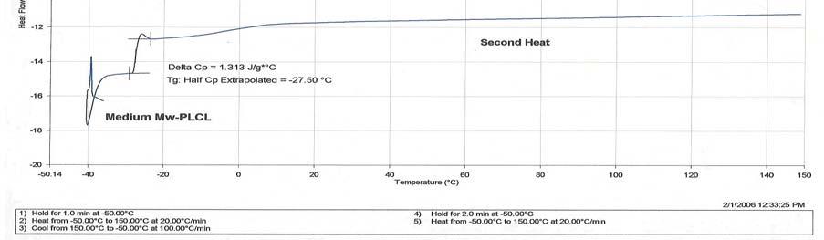
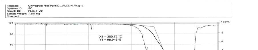
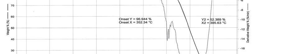
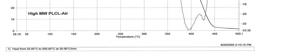
132 DSC curve for PLCL (Mw-110,000) TGA curve for PLCL (Mw-350,000) under air 119

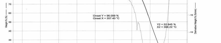
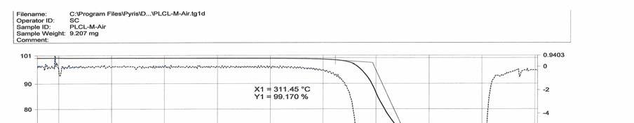
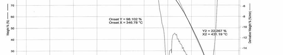
133 TGA curve for PLCL (Mw-350,000) under N 2 TGA curve for PLCL (Mw-110,000) under air 120

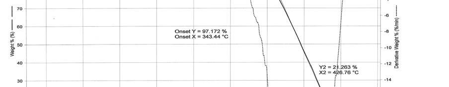
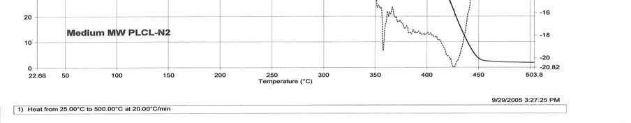
134 TGA curve for PLCL (Mw-110,000) under N 2 121
Artificial blood vessels
 Artificial blood vessels S. Swaminathan Director Centre for Nanotechnology & Advanced Biomaterials School of Chemical & Biotechnology SASTRA University Thanjavur 613 401 Tamil Nadu Joint Initiative of
Bioreactors in tissue engineering
 Bioreactors in tissue engineering S. Swaminathan Director Centre for Nanotechnology & Advanced Biomaterials School of Chemical & Biotechnology SASTRA University Thanjavur 613 401 Tamil Nadu Joint Initiative
Prof. Steven S. Saliterman. Department of Biomedical Engineering, University of Minnesota
 Department of Biomedical Engineering, University of Minnesota http://saliterman.umn.edu/ Mimicking the fibrillar structure of the extracellular matrix is important for scaffolds. Clinical trails to date
Stem cells and tissue engineering
 Stem cells and tissue engineering S. Swaminathan Director Centre for Nanotechnology & Advanced Biomaterials School of Chemical & Biotechnology SASTRA University Thanjavur 613 401 Tamil Nadu Joint Initiative
PRINCIPLES AND PRACTICE OF TISSUE ENGNEERING:
 Harvard-MIT Division of Health Sciences and Technology HST.535: Principles and Practice of Tissue Engineering Instructor: Myron Spector Massachusetts Institute of Technology Harvard Medical School Brigham
White Paper: Textile Engineered Tissue Scaffolds Offer Advances in Hollow Organ Regenerations. Peter D. Gabriele Director, Emerging Technology
 White Paper: Textile Engineered Tissue Scaffolds Offer Advances in Hollow Organ Regenerations Peter D. Gabriele Director, Emerging Technology Regenerative medicine (RM) holds the potential to address some
BEH.462/3.962J Molecular Principles of Biomaterials Spring 2003
 Lecture 6: Biodegradable Polymers for Tissue Engineering Last time: Today: enzymatic degradation of solid polymers Engineering biological recognition of polymers Designing polymers for tissue engineering
Effect of CNTs on Shape memory properties of PLLA/PCL blends
 Effect of CNTs on Shape memory properties of PLLA/PCL blends Maryam Amirian 1, Ali Nabipour Chakoli 2, Hossein Afarideh 3, t=0s t=2s t=5s t=10s t=15s t=20s 1 Dep. of Physics, Teachers Uni., Tehran, Iran,
UNIT CELL PROCESSES UNDERLYING TISSUE ENGINEERING AND REGENERATIVE MEDICINE
 Massachusetts Institute of Technology Harvard Medical School Brigham and Women s Hospital VA Boston Healthcare System 2.79J/3.96J/20.441/HST522J UNIT CELL PROCESSES UNDERLYING TISSUE ENGINEERING AND REGENERATIVE
Design of scaffolds with computer assistance
 Modelling in Medicine and Biology VII 157 Design of scaffolds with computer assistance H. A. Almeida 1, P. J. Bártolo 1 & J. C. Ferreira 2 1 Centre for Rapid and Sustainable Product Development CDRsp,
STUDIES ON DRY-JET-WET SPINNING OF POLY(LACTIC ACID) FILAMENT AND ITS KNITTING. Doctor of Philosophy
 FILAMENT AND ITS KNITTING. Doctor of Philosophy") STUDIES ON DRY-JET-WET SPINNING OF POLY(LACTIC ACID) FILAMENT AND ITS KNITTING By NILESH S. REVAGADE Department of Textile Technology Submitted In fulfillment of the requirements of the degree of Doctor
STUDIES ON DRY-JET-WET SPINNING OF POLY(LACTIC ACID) FILAMENT AND ITS KNITTING By NILESH S. REVAGADE Department of Textile Technology Submitted In fulfillment of the requirements of the degree of Doctor
Mechanical Characterization and Stimulation Solutions for Biomaterials
 Mechanical Characterization and Stimulation Solutions for Biomaterials BioDynamic Instruments Biomaterials and Tissue Characterization Application Examples Bone Bending Creep Test Clinical Need: Understand
White Paper: Designing Functional Fabrics for Today s Heart Valves and Beyond
 White Paper: Designing Functional Fabrics for Today s Heart Valves and Beyond Ryan Heniford Business Development Director Peter Gabriele Director, Emerging Technology How fabrics can be used in heart valves,
Subject Index. Antithrombotic drugs See Drugs, antithrombotic
 STP898-EB/Sep. 1986 Subject Index A Absorbable vascular grafts, 197-217 Acellular vascular matrix, 219-235 Aneurysm, 58, 98 See also Failure, vascular grafts Animal experimental models baboon, endothelial
1) Determining the best cell sources and scaffold materials for TEHV development.
 Determining the best cell sources and scaffold materials for TEHV development.") Broadly speaking, my primary research interests focus on the development and application of methodologies that can be employed in the basic understanding and optimization of tissue engineered heart valves
Broadly speaking, my primary research interests focus on the development and application of methodologies that can be employed in the basic understanding and optimization of tissue engineered heart valves
A Thesis Presented to the Faculty of California Polytechnic State University, San Luis Obispo
 PREPARATION AND CHARACTERIZATION OF ELECTROSPUN POLY(D,L-LACTIDE-CO-GLYCOLIDE) SCAFFOLDS FOR VASCULAR TISSUE ENGINEERING AND THE ADVANCEMENT OF AN IN VITRO BLOOD VESSEL MIMIC A Thesis Presented to the
Mechano-dependent biosynthetic response of microintegrated cells in elastomeric scaffolds.
 Mechano-dependent biosynthetic response of microintegrated cells in elastomeric scaffolds. Lauren Anderson, Department of Bioengineering, The Pennsylvania State University Dr. Michael Sacks, Mentor, Department
Regenerez : A Next-Generation Material for Functional Bioresorbable Coatings. by Carissa Smoot and Jeremy Harris, Ph.D, Secant Medical, Inc.
 Regenerez : A Next-Generation Material for Functional Bioresorbable Coatings by Carissa Smoot and Jeremy Harris, Ph.D, Secant Medical, Inc. Coatings consisting of natural and synthetic origin play an important
Tissue Engineered Vascular Grafts
 Tissue Engineered Vascular Grafts Jeffrey H. Lawson, M.D., Ph.D. Chief Medical Officer Humacyte Incorporated Professor of Surgery and Pathology Duke University Medical Center Disclosure Information Financial
Active biomaterials/scaffolds for stem cell-based soft tissue engineering (in a nutshell )
") Active biomaterials/scaffolds for stem cell-based soft tissue engineering (in a nutshell ) Emanuele Giordano Responsabile Lab ICM BioEngLab DEI CIRI SdV-TS Università di Bologna emanuele.giordano@unibo.it
Active biomaterials/scaffolds for stem cell-based soft tissue engineering (in a nutshell ) Emanuele Giordano Responsabile Lab ICM BioEngLab DEI CIRI SdV-TS Università di Bologna emanuele.giordano@unibo.it
Studies on the Effect of Molecular Weight on the Degradation Rate of Biodegradable Polymer Membrane
 , pp.390-394 http://dx.doi.org/10.14257/astl.2015. Studies on the Effect of Molecular Weight on the Degradation Rate of Biodegradable Polymer Membrane Yuying Xie 1, Jong-soon Park 2, Soon-kook Kang 1,1
INFLUENCE OF STRUCTURAL ANISOTROPY ON COMPRESSIVE FRACTURE PROPERTIES OF HYDROSTATIC-PRESSURE-EXTRUSION-MOLDED HAP/PLLA COMPOSITE
 18 TH INTERNATIONAL CONFERENCE ON COMPOSITE MATERIALS INFLUENCE OF STRUCTURAL ANISOTROPY ON COMPRESSIVE FRACTURE PROPERTIES OF HYDROSTATIC-PRESSURE-EXTRUSION-MOLDED HAP/PLLA COMPOSITE M. Tanaka 1 *, Y.
Applications in Cardiology Hollow Fiber Membranes and Applications
 Applications in Cardiology Want is meant by the term silicones?; Describe in general terms a typical synthetic scheme for a silicone consisting of half PDMS and half polysiloxane; Describe three cross-linking
Surface Characterization of Biomaterials
 Surface Characterization of Biomaterials Biomaterials are determined The desire for well-being and long life expectancy goes hand in-hand with the use of non-viable materials to conserve health. 2000 years
INFLUENCE OF THE SURFACE MORPHOLOGY AT SPECIFIC SURFACE AREA OF MICROFIBRES MADE FROM POLY (L-LACTIDE) MACAJOVÁ Eva
 MACAJOVÁ Eva") INFLUENCE OF THE SURFACE MORPHOLOGY AT SPECIFIC SURFACE AREA OF MICROFIBRES MADE FROM POLY (L-LACTIDE) MACAJOVÁ Eva Department of Material Science, Technical University of Liberec, Liberec, Czech Republic,
INFLUENCE OF THE SURFACE MORPHOLOGY AT SPECIFIC SURFACE AREA OF MICROFIBRES MADE FROM POLY (L-LACTIDE) MACAJOVÁ Eva Department of Material Science, Technical University of Liberec, Liberec, Czech Republic,
Mechano-dependent Biosynthetic Response of Micro-integrated Cells in Elastomeric Scaffolds
 Mechano-dependent Biosynthetic Response of Micro-integrated Cells in Elastomeric Scaffolds Lauren Anderson 1,2, John Stella 3, and Dr. Michael Sacks 3 1 Bioengineering and Bioinformatics Summer Institute,
Chapter 8. Comparison of static vs dynamic culture
 Chapter 8 Comparison of static vs dynamic culture 8.1. Literature Review Articular cartilage is a load-bearing connective tissue in which its functions not only transmitting the compressive joint loads
2. Precision Extrusion Deposition Previous research has focused on Fuse Deposition Modeling (FDM) for the fabrication of
 for the fabrication of") PRECISION EXTRUSION DEPOSITION OF POLYCAPROLACTONE/ HYDROXYAPATITE TISSUE SCAFFOLDS L. Shor, S. Güçeri, W. Sun Laboratory for Computer-Aided Tissue Engineering Department of Mechanical Engineering and
PRECISION EXTRUSION DEPOSITION OF POLYCAPROLACTONE/ HYDROXYAPATITE TISSUE SCAFFOLDS L. Shor, S. Güçeri, W. Sun Laboratory for Computer-Aided Tissue Engineering Department of Mechanical Engineering and
Supporting Information
 Supporting Information Novel Interwoven Polymer Composites via Dual- Electrospinning with Shape Memory/Self-healing Properties Jaimee M. Robertson, Hossein Birjandi Nejad, Patrick T. Mather* Syracuse Biomaterials
Cell and Tissue Engineering, Nanotechnology
 Cell and Tissue Engineering, Nanotechnology Cells Tissue Engineering Scaffolds BIOE 506 Muqeem Qayyum Biorectors Signals Why? In-vitro In-vivo Because we can no longer to view a cell as self contained
Articular Cartilage Engineering Using Human Mesenchymal Stem Cells and Nanostructured Biomaterials
 Articular Cartilage Engineering Using Human Mesenchymal Stem Cells and Nanostructured Biomaterials REU Participant: Nicole Green 1 Advisors: Joel Wise 2, Dr. Michael Cho 2, Dr. Constantine Megaridis 3
Biomaterials. Third Edition
 Biomaterials Third Edition Joon Park R.S. Lakes Biomaterials An Introduction Third Edition Joon Park Biomedical and Mechanical Engineering University of Iowa Iowa City, IA 52242-1414 USA joon-park@uiowa.edu
Empowering innovation.
 Empowering innovation. RESOMER is a synonym for innovation and vision, enabling both pharma and medical device companies to shape and design a better future. 30 years of RESOMER The history of RESOMER
Affinity. A Paradigm Shift in Skeletal Reconstruction
 Affinity A Paradigm Shift in Skeletal Reconstruction INTRODUCING TRS AFFINITY SKELETAL RECONSTRUCTION BREAKTHROUGH Tissue Regeneration Systems (TRS ) is a start-up medical device company commercializing
W BIOENGINEERING. Nanomaterials Applications in Biology and Medicine. Topics:
 Nanomaterials Applications in Biology and Medicine Obejctive: Develop a firm understanding of the fundamental materials science and engineering principles underlying synthetic/engineered materials used
Course Handbook MSc in Bioengineering Tissue Engineering Specialisation
 Course Handbook 2013-2014 MSc in Bioengineering Tissue Engineering Specialisation 1 Course Objectives & Learning Outcomes This programme aims to give a sound and broad basis in tissue engineering. In particular,
Polymeric hydrogels are of special importance in polymeric biomaterials because of
 POLYMERIC HYDROGELS Polymeric hydrogels are of special importance in polymeric biomaterials because of their favorable biocompatibility. Hydrogels are cross-linked macromolecular networks formed by hydrophilic
The Electrospinning Company
 The Electrospinning Company September 2015 Contact: info@electrospinning.co.uk +44 1235 567276 UK SME Design, develop and manufacture advanced biomaterial scaffolds Sales of product and service R&D collaborations
Pittsburgh Tissue Engineering Initiative Annual Progress Report: 2010 Formula Grant
 Pittsburgh Tissue Engineering Initiative Annual Progress Report: 2010 Formula Grant Reporting Period July 1, 2011 December 31, 2011 Formula Grant Overview The Pittsburgh Tissue Engineering Initiative,
Tissue Engineering: The art of growing body parts. Robby Bowles, Ph.D Cornell University
 Tissue Engineering: The art of growing body parts Robby Bowles, Ph.D Cornell University What is Tissue Engineering? What is Tissue Engineering? TE is an interdisciplinary field that applies the principles
Hydrogels. Soft materials for tissue repair Contact lenses Slow or smart drug release implants Diaper absorbent Toys (slime) food
 food") Hydrogels A hydrogel is a gel in which water is the dispersed media Hydrogel is typically a 3D network of hydrophilic polymer molecules that attract water molecules Many applications, including Soft materials
Hydrogels A hydrogel is a gel in which water is the dispersed media Hydrogel is typically a 3D network of hydrophilic polymer molecules that attract water molecules Many applications, including Soft materials
CELLULAR AND FIBRE-REINFORCED COMPOSITES FOR BONE ENGINEERING
 16 TH INTERNATIONAL CONFERENCE ON COMPOSITE MATERIALS CELLULAR AND FIBRE-REINFORCED COMPOSITES FOR BONE ENGINEERING Manuel Bühler, Pierre-Etienne Bourban, Jan-Anders E. Månson Laboratoire de Technologie
CHARACTERIZATION AND APPLICATION OF COLLAGEN-POLYMER BASED COMPOSITE AS WOUND HEALING MATERIAL
 th ICAMS 2012 4 International Conference on Advanced Materials and Systems CHARACTERIZATION AND APPLICATION OF COLLAGEN-POLYMER BASED COMPOSITE AS WOUND HEALING MATERIAL DENİZ GÜRLER, EYLEM KILIÇ Uşak
CHALLENGES OF 3D BIOPRINTING IN CLINICAL PRACTICE
 CENTRE DE THÉRAPIE TISSULAIRE & CELLULAIRE CHALLENGES OF 3D BIOPRINTING IN CLINICAL PRACTICE Pr. D. Dufrane MD, PhD 3D-BIOPRINTING: MYTH OR REALITY? 2 REGENERATIVE MEDICINE FOR ORGAN AND TISSUE A LARGE
How do we find ultimate properties?
 Introduction Why ultimate properties? For successful product design a knowledge of the behavior of the polymer is important Variation in properties over the entire range of operating conditions should
Solubility and Diffusivity of Supercritical CO 2 in Bioresorbable Polymers: Measurements, Calculations and Potential Applications in Polymer Foaming
 Solubility and Diffusivity of Supercritical CO 2 in Bioresorbable Polymers: Measurements, Calculations and Potential Applications in Polymer Foaming Elena Aionicesei, Mojca Škerget, Željko Knez* University
Lecture Outline. History. Purpose? Func:on of Bioscaffolds. Extracellular Matrix (ECM) 12/08/15
 12/08/15") Associate Professor Rod Dilley Dr Rob Marano Ear Sciences Centre School of Surgery Harry Perkins Research Building 4 th Floor Lecture Outline History Purpose Functions Properties Approaches to bioscaffold
Associate Professor Rod Dilley Dr Rob Marano Ear Sciences Centre School of Surgery Harry Perkins Research Building 4 th Floor Lecture Outline History Purpose Functions Properties Approaches to bioscaffold
INVESTIGATION OF HIGHLY POROUS POLY(Ε-CAPROLACTONE)
") szerzoi_jav_005_036.qxd 2008.06.20. 16:00 Page 30 INVESTIGATION OF HIGHLY POROUS POLY(Ε-CAPROLACTONE) SCAFFOLDS László Oláh 1, Lajos Borbás 2, Tibor Czigány 3 1 Polymer Competence Center Leoben GmbH 2
szerzoi_jav_005_036.qxd 2008.06.20. 16:00 Page 30 INVESTIGATION OF HIGHLY POROUS POLY(Ε-CAPROLACTONE) SCAFFOLDS László Oláh 1, Lajos Borbás 2, Tibor Czigány 3 1 Polymer Competence Center Leoben GmbH 2
FINAL PUBLISHABLE SUMMARY REPORT
 FINAL PUBLISHABLE SUMMARY REPORT Grant Agreement number: 310389 Project acronym: BIP-UPY Project title: Bioactive Implantable Polymers based on Ureido-Pyrimidinone Funding Scheme: Large-scale integrating
Abstract Process Economics Program Report 115B ENVIRONMENTALLY DEGRADABLE POLYMERS (December 1994)
") Abstract Process Economics Program Report 115B ENVIRONMENTALLY DEGRADABLE POLYMERS (December 1994) First generation biodegradable polymers, which were largely commercialized in the 1980s, did not satisfy
Abstract Process Economics Program Report 115B ENVIRONMENTALLY DEGRADABLE POLYMERS (December 1994) First generation biodegradable polymers, which were largely commercialized in the 1980s, did not satisfy
Additive manufacturing for long term implants. Presentation Content
 Additive manufacturing for long term implants Jac Koenen DSM Amsterdam February 4, 2015 Presentation Content DSM and DSM 3D printing of medical devices/implants Advantages Unique DSM materials Some Relevant
Endothelium conference
 Endothelium conference Epithelium FUNCTIONS: COVER ORGANS, LINE VISCERA AND BLOOD VESSELS, SECRETORY CELLS OF GLANDS DISTINGUISHING FEATURES AND DISTRIBUTION: ALWAYS SIT ON A BASEMENT MEMBRANE, BUT COME
Bioabsorbable Stents. The Ideal Scaffold properties and kinetics. Jonathan Hill King s College Hospital King s Health Partners
 Bioabsorbable Stents The Ideal Scaffold properties and kinetics Jonathan Hill King s College Hospital King s Health Partners Transient Biodegradable Scaffold Building a skyscraper in Hong Kong with bamboo
ISTINYE UNIVERSITY INSTITUTE OF HEALTH SCIENCES DEPARTMENT OF STEM CELL AND TISSUE ENGINEERING (THESIS) COURSE DESCRIPTIONS
 COURSE DESCRIPTIONS") ISTINYE UNIVERSITY INSTITUTE OF HEALTH SCIENCES DEPARTMENT OF STEM CELL AND TISSUE ENGINEERING (THESIS) COURSE DESCRIPTIONS 1 st SEMESTER Adult Stem Cell Biology 5 ECTS In this course, the characteristics
ISTINYE UNIVERSITY INSTITUTE OF HEALTH SCIENCES DEPARTMENT OF STEM CELL AND TISSUE ENGINEERING (THESIS) COURSE DESCRIPTIONS 1 st SEMESTER Adult Stem Cell Biology 5 ECTS In this course, the characteristics
LASER WELDING OF BIODEGRADABLE POLYGLYCOLIC ACID (PGA) BASED POLYMER FELT SCAFFOLDS SOUMYA SAMBIT ROUT
 BASED POLYMER FELT SCAFFOLDS SOUMYA SAMBIT ROUT") LASER WELDING OF BIODEGRADABLE POLYGLYCOLIC ACID (PGA) BASED POLYMER FELT SCAFFOLDS by SOUMYA SAMBIT ROUT B.E., Visveswariah Technological University, India, 2005 A THESIS submitted in partial fulfillment
LASER WELDING OF BIODEGRADABLE POLYGLYCOLIC ACID (PGA) BASED POLYMER FELT SCAFFOLDS by SOUMYA SAMBIT ROUT B.E., Visveswariah Technological University, India, 2005 A THESIS submitted in partial fulfillment
MatSE 259 Exam 4 Review Session
 MatSE 259 Exam 4 Review Session 1. Same exam format and protocol as the previous three 2. If your score for any of the previous exams needs to be updated in the school records (entered wrong SID, left
1 Publishable summary
 1 Publishable summary 1.1 Summary of project objectives Valve replacement with mechanical or bioprosthetic prostheses is the most common intervention for valvular disease, with almost 300.000 annual replacements
implants Biotextiles as medical Bhupender S. Gupta and Robert Guidoin TheTextile Institute Edited by Martin W. King,
 Woodhead Publishing Series in Textiles: Number 113 Biotextiles as medical implants Edited by Martin W. King, Bhupender S. Gupta and Robert Guidoin TheTextile Institute WP WOODHEAD PUBLISHING Oxford Cambridge
Regenerez : A Next-Generation Material for Bioresorbable Coatings
 R Regenerez : A Next-Generation Material for Bioresorbable Coatings A White Paper by Carissa Smoot, Scientist, Secant Group and Jeremy Harris, Ph.D, Secant Group Coatings consisting of natural and synthetic
Electrospun collagen fibers for tissue regeneration applications
 Western University Scholarship@Western Electronic Thesis and Dissertation Repository October 2018 Electrospun collagen fibers for tissue regeneration applications Ying Li The University of Western Ontario
Finite element analysis of degradation of biodegradable medical devices
 Page 1 of 10 Medical Biotechnology Finite element analysis of degradation of biodegradable medical devices X Han 1, J Pan 2 * Abstract Introduction This paper presents a set of case studies for calculating
Material s Engineering Branch Fall 2013
 Material s Engineering Branch Fall 2013 Department of Civil, Environmental and Architectural Engineering Piazzale J.F.Kennedy 1, Pad D, 16129, Genoa, Italy Fabrizio Barberis SERP CHEM: Introduction to
Introduction to Cell/ Biomaterial Engineering
 Introduction to Cell/ Biomaterial Engineering Module 3, Lecture 1! 20.109 Spring 2011! Topics for Lecture 1 Introduction to tissue engineering! motivation! basic principles + examples! Introduction to
Biodegradation of poly(εcaprolactone)/poly(lactic. composites: The effect of fiber load and compatibilization
/poly(lactic. composites: The effect of fiber load and compatibilization") About OMICS Group OMICS Group International is an amalgamation of Open Access publications and worldwide international science conferences and events. Established in the year 2007 with the sole aim of
About OMICS Group OMICS Group International is an amalgamation of Open Access publications and worldwide international science conferences and events. Established in the year 2007 with the sole aim of
Vascular Mechanobiology: Towards Control of In Situ Regeneration
 cells Review Vascular Mechanobiology: Towards Control of In Situ Regeneration Eline E. van Haaften 1,2, Carlijn V. C. Bouten 1,2 and Nicholas A. Kurniawan 1,2, * 1 Department of Biomedical Engineering,
Bone Tissue Engineering
 Bone Tissue Engineering Miqin Zhang University of Washington Dept of Materials Science and Engineering Funded by UWEB: A National Science Foundation Engineering Research Center (NSF-EEC 9529161) Bone Defects
Bioartificial Surfaces
 Bioartificial Surfaces Blood surface interaction E. Wolner, M. Vögele-Kadletz Medical University of Vienna Blood contact Vascular prosthesis Circulatory assist devices Heart lung machine: ECMO Artificial
Tissue Engineering for Blood Vessels
 Regenerative Medicine Tissue Engineering for Blood Vessels JMAJ 47(6): 288 293, 2004 Narutoshi HIBINO and Toshiharu SHIN OKA Department of Cardiovascular Surgery, Heart Institute of Japan, Tokyo Women
Ceramics, Cracow, Poland
 Chemically and physically functionalized carbon composites a prospective material for tissue treatment S.Blazewicz 1*, E.Stodolak 1, E. Staszkow 2, T.Mikolajczyk 3 1 AGH University of Science and Technology,
CHAPTER 4 LANGMUIR FILMS AT THE AIR/WATER INTERFACE
 CHAPTER 4 GROWTH OF POLY(ε-CAPROLACTONE) CRYSTALS IN LANGMUIR FILMS AT THE AIR/WATER INTERFACE Reproduced with permission from: Li, B.; Wu, Y.; Liu, M.; Esker, A. R. Brewster Angle Microscopy Study of
Effect of Target Shapes on Distribution of Polyacrylonitrile Nanofibers Prepared by Electrospinning Process
 109 Effect of Target Shapes on Distribution of Polyacrylonitrile Nanofibers Prepared by Electrospinning Process Bussarin Ksapabutr *, Chaowat Waikru and Manop Panapoy Department of Materials Science and
BFF1113 Engineering Materials DR. NOOR MAZNI ISMAIL FACULTY OF MANUFACTURING ENGINEERING
 BFF1113 Engineering Materials DR. NOOR MAZNI ISMAIL FACULTY OF MANUFACTURING ENGINEERING Course Guidelines: 1. Introduction to Engineering Materials 2. Bonding and Properties 3. Crystal Structures & Properties
Regenerative Strategies for Vascular and Lung Tissues. Laura E Niklason MD, PhD
 Regenerative Strategies for Vascular and Lung Tissues Laura E Niklason MD, PhD Disclosure: Some of this work in this presentation is from Humacyte Inc. Niklason is a founder of Humacyte, and holds stock
Production and commercialisation of vascularized and customized bone Clinical trials, market authorisation Pre-clinical trials
 Production and commercialisation of vascularized and customized bone Clinical trials, market authorisation Pre-clinical trials Basic Research: scaffolds, cells/ media, in vivo imaging, modelling www.vascubone.eu
In Vitro Fatigue Properties of Prototype Woven Vascular Prosthesis with Poly (trimethylene terephthalate) Filaments as Circumferential Yarns
 Filaments as Circumferential Yarns") In Vitro Fatigue Properties of Prototype Woven Vascular Prosthesis with Poly (trimethylene terephthalate) Filaments as Circumferential Yarns Ying Chen, Xin Ding, Yuling Li, Xueqian Zhao College of Textiles,
In Vitro Fatigue Properties of Prototype Woven Vascular Prosthesis with Poly (trimethylene terephthalate) Filaments as Circumferential Yarns Ying Chen, Xin Ding, Yuling Li, Xueqian Zhao College of Textiles,
Stent-based anastomotic coupler
 Stent-based anastomotic coupler Design Team Nick Cote, Ryan Myers Matthew Ouellette, Jessica Patel David Schecter Design Advisor Prof. Jeffrey Ruberti Email: J.Ruberti@neu.edu Abstract Microvascular anastomosis
Direct Electrospinning Writing
 2-26-2018 Biofabrication Workshop Biomaterials Lab and Center for Engineering Complex Tissues Anthony J. Melchiorri, Ph.D. Associate Director, Biomaterials Lab Rice University Hochleitner, et al. Biofabrication.
Journal of Biomedical Materials Research, Vol. 20, (1986) John Wiley & Sons, Inc.
 John Wiley & Sons, Inc.") Journal of Biomedical Materials Research, Vol. 20, 861-865 (1986) 0 1986 John Wiley & Sons, Inc. 862 Characterization of morphologic and mechanical properties of surgical mesh fabrics C. C. Chu, B. Pourdeyhimi,*
Journal of Biomedical Materials Research, Vol. 20, 861-865 (1986) 0 1986 John Wiley & Sons, Inc. 862 Characterization of morphologic and mechanical properties of surgical mesh fabrics C. C. Chu, B. Pourdeyhimi,*
Tissue Engineering of the Mitral Valve Leaflets and Abdominal Aorta
 Medizinische Hochschhule Hannover Dr Morticelli L Supervisor: Dr Korossis S Niedersächsischen Zentrum für Biomedizintechnik und Implantatforschung The Tissue Engineering (TE) Concept Tissue Engineering
Tissue Engineered Medical Products
 WORKSHOP 8 Tissue Organizer: Jeremy J. Rawlinson PhD Speakers: Jack E. Lemons, PhD Lawrence J. Bonassar, PhD Mauro R. Alini, PhD Michael J. Yaszemski, MD, PhD Standards for Tissue J. Lemons, University
ELECTROSPUN NANOFIBER PROCESS CONTROL
 CELLULOSE CHEMISTRY AND TECHNOLOGY Received April 26, 2010 ELECTROSPUN NANOFIBER PROCESS CONTROL University of Guilan, P.O. Box 3756, Rasht, Iran Fiber diameter is an important structural characteristic
Tissue Engineering and Regenerative Medicine
 Tissue Engineering and Regenerative Medicine NIH Center for Engineering Complex Tissues (CECT) June 8, 2018 Bhushan Mahadik, Ph.D. Assistant Director, CECT University of Maryland Regenerative Medicine
Engineering The Future
 Engineering The Future The world s preferred supplier of biodegradable polymers, polymer-based technologies, and polymeric products for the drug delivery and medical device industries. Greetings When I
By: Sara Anam, Garni Tatikian
 By: Sara Anam, Garni Tatikian Thousands of people die every year waiting for organs from a donor Mechanical solutions (kidney dialysis, heart-lung bypass machines, etc.) and synthetic solutions (blood
Natural Fibers and Innovative
 Natural Fibers and Innovative Biomaterials i for Medical lapplications Dr. Michael Wöltje 33rd International Cotton Conference Bremen, 17.03.2016 Classification of textile fibers Textile fibers Natural
Growth factor delivery
 Growth factor delivery S. Swaminathan Director Centre for Nanotechnology & Advanced Biomaterials School of Chemical & Biotechnology SASTRA University Thanjavur 613 401 Tamil Nadu Joint Initiative of IITs
FABRICATION AND CHARACTERIZATION OF POROUS POLYURETHANE SCAFFOLD FOR APPLICATION IN THE FIELD OF TISSUE ENGINEERING. A Thesis.
 FABRICATION AND CHARACTERIZATION OF POROUS POLYURETHANE SCAFFOLD FOR APPLICATION IN THE FIELD OF TISSUE ENGINEERING A Thesis Presented to The Graduate Faculty of The University of Akron In Partial Fulfillment
NEXT GENERATION ECM-BASED ALLOGRAFT TECHNOLOGY:
 NEXT GENERATION ECM-BASED ALLOGRAFT TECHNOLOGY: Potent biological scaffolds strategically control stem cell fate and function, allowing our allografts to harness the regenerative potential of patient s
Scaffolding Materials for Tissue Engineering. Parisa Bahrami, Hailun(Helen) Huang 1
 Huang 1") Scaffolding Materials for Tissue Engineering Parisa Bahrami, Hailun(Helen) Huang 1 Content What is tissue scaffolding History of tissue scaffolding Types of tissue scaffolding Materials used in tissue
Scaffolding Materials for Tissue Engineering Parisa Bahrami, Hailun(Helen) Huang 1 Content What is tissue scaffolding History of tissue scaffolding Types of tissue scaffolding Materials used in tissue
FABRICATION OF LAYER-BY-LAYER ELECTROSPUN COMPOSITE MEMBRANES BASED ON POLYLACTIC ACID (PLA) AND POLY (CAPROLACTONE) (PCL)/CHITOSAN
 AND POLY (CAPROLACTONE) (PCL)/CHITOSAN") FABRICATION OF LAYER-BY-LAYER ELECTROSPUN COMPOSITE MEMBRANES BASED ON POLYLACTIC ACID (PLA) AND POLY (CAPROLACTONE) (PCL)/CHITOSAN Choi Yee Foong 1 and Naznin Sultana 1, 2 1 Faculty of Biosciences and
FABRICATION OF LAYER-BY-LAYER ELECTROSPUN COMPOSITE MEMBRANES BASED ON POLYLACTIC ACID (PLA) AND POLY (CAPROLACTONE) (PCL)/CHITOSAN Choi Yee Foong 1 and Naznin Sultana 1, 2 1 Faculty of Biosciences and
A UNIQUE POLYESTER DRUG/DEVICE VASCULAR GRAFT INTERGARD HEPARIN
 A UNIQUE POLYESTER DRUG/DEVICE VASCULAR GRAFT INTERGARD HEPARIN FACTS ON INTERGARD HEPARIN Most frequent causes of vascular graft failure and associated limb loss 1 Graft occlusion due to the development
Sterilization Techniques Influence Physical Properties and Cell-Biomaterial Interactions in Plasticized Polylactide Foam Scaffolds
 Sterilization Techniques Influence Physical Properties and Cell-Biomaterial Interactions in Plasticized Polylactide Foam Scaffolds Matthieu Cuenoud, PhD 1, Salim Elias Darwiche, PhD 1, John Christopher
Endovascular Device Testing A Survey of Requirements for Product Validation
 MET A4 1p Endovascular Device Testing Info Sheet-02.qxp_MET A4 1p Endovascular Device Testing Info Sheet.qxp 05/04/2016 09:58 Page 1 Endovascular Device Testing A Survey of Requirements for Product Validation
Regenerez Degradation and Release Kinetics White Paper
 R Regenerez Degradation and Release Kinetics White Paper A White Paper by Carissa Smoot, Scientist, Secant Group, Jeremy Harris, Ph.D, Secant Group and Stephanie Reed, Ph.D, Secant Group Introduction Implantable
Disclosure-Yaszemski
 Current and Future Uses of Additive Manufacturing in Neurologic, Musculoskeletal, Spinal, and Oncologic Surgery Michael J. Yaszemski, M.D., Ph.D. John & Posy Krehbiel Endowed Professor of Orthopedic Surgery
The research work highlights the development and evaluation of. bioavailability of drugs. The buccal route can bypass the first-pass
 212 9. Summary, conclusion and recommendation 9.1 Summary and conclusion The research work highlights the development and evaluation of novel transbuccal drug antagonist of Famotidine. route have a rapid
CHAPTER 1. Survey of Clinical Cases of Biomaterials-Tissue Interactions: The Paradigm
 CHAPTER 1 Survey of Clinical Cases of Biomaterials-Tissue Interactions: The Paradigm 1.1 Introduction 1.2 Genotype/Phenotype (Fig. 1.1) 1.3 The Working Paradigm: The Unit Cell Process/The Control Volume
Lecture 6: Programmed/Pulsed Drug Delivery and Drug Delivery in Tissue Engineering
 Lecture 6: Programmed/Pulsed Drug Delivery and Drug Delivery in Tissue Engineering Last time: principles of controlled release from solid polymers Today: Reading: Pulsatile/regulated/multifactor controlled
Kick-off meeting. Introducing: INNOVENT e. V. Barcelona, 3-5 March 2014
 DEVELOPMENT OF SUSTAINABLE INTERRELATIONS BET- WEEN EDUCATION, RESEARCH AND INNOVATION AT WBC UNIVERSITIES IN NANOTECHNOLOGIES AND ADVANCED MATERIALS WHERE INNOVATION MEANS BUSINESS Introducing: INNOVENT
An Investigation of the Synthesis of Ti-50 At. Pct Ni Alloys through Combustion Synthesis and Conventional Powder Sintering
 An Investigation of the Synthesis of Ti-50 At. Pct Alloys through Combustion Synthesis and Conventional Powder Sintering BING-YUN LI, LI-JIAN RONG, YI-YI LI, and V.E. GJUNTER * Institute of Metal Research,