Fabrication of 3D Ultrafine Fibrous Protein Structures via Freeze-Drying
|
|
|
- Marybeth Page
- 5 years ago
- Views:
Transcription

1 University of Nebraska - Lincoln DigitalCommons@University of Nebraska - Lincoln Textiles, Merchandising and Fashion Design: Dissertations, Theses, & Student Research Textiles, Merchandising and Fashion Design, Department of Winter Fabrication of 3D Ultrafine Fibrous Protein Structures via Freeze-Drying Yiling Huang University of Nebraska-Lincoln, orangehyl2008@hotmail.com Follow this and additional works at: Part of the Biology and Biomimetic Materials Commons, and the Other Materials Science and Engineering Commons Huang, Yiling, "Fabrication of 3D Ultrafine Fibrous Protein Structures via Freeze-Drying" (2014). Textiles, Merchandising and Fashion Design: Dissertations, Theses, & Student Research This Thesis is brought to you for free and open access by the Textiles, Merchandising and Fashion Design, Department of at DigitalCommons@University of Nebraska - Lincoln. It has been accepted for inclusion in Textiles, Merchandising and Fashion Design: Dissertations, Theses, & Student Research by an authorized administrator of DigitalCommons@University of Nebraska - Lincoln.
2 FABRICATION OF 3D ULTRAFINE FIBROUS PROTEIN STRUCTURES VIA FREEZE-DRYING by Yiling Huang A THESIS Presented to the Faculty of The Graduate College at the University of Nebraska In Partial Fulfillment of Requirements For the Degree of Master of Science Major: Textiles, Merchandising and Fashion Design Under the Supervision of Professor Yiqi Yang Lincoln, Nebraska November, 2014
3 FABRICATION OF 3D ULTRAFINE FIBROUS PROTEIN STRUCTURES VIA FREEZE-DRYING Yiling Huang, M.S. University of Nebraska, 2014 Advisor: Yiqi Yang In this thesis, ultrafine fibrous 3D matrices were fabricated using three different proteins (soy protein, wool keratin, and chicken feather keratin) via freeze-drying. Protein matrices are preferable for tissue engineering compared to matrices made from synthetic material because of their similarity to native extracellular matrices. Due to their cell-binding motifs, natural proteins are also recognized as more biocompatible compared. Freeze-drying, which is a simple method used to produce 3D sponge matrices, was employed in this study to fabricate 3D fibrous matrices in a controlled manner. The inner structures of the 3D matrices fabricated ranged from film to fibers, and the diameters of the fibers ranged from the micro scale down to the nano scale. This controlled fabrication of protein matrices was achieved by individually varying protein concentration, SDS concentration, and freezing time. The techniques developed in this study to fabricate ultrafine fibrous 3D protein matrices could potentially be applied to other proteins and be used in tissue engineering applications.
4 Copyright 2014, Yiling Huang
5 Acknowledgement First and foremost, I want to thank my advisor Dr. Yiqi Yang for his valuable advice, keen insights, inspiration, and encouragement throughout the completion of this work. I am also sincerely grateful to the support Dr. Barbara Trout who has always showed great interests in my research. In addition to my research, thank you for encouraging me to model in the UNL fashion show. It is one of the most memorable experiences that I have had during my time at UNL. I also want to thank Dr. Helan Xu who was closely involved in my research and whose advice was very helpful. I am also extremely grateful to my lab-mates and my friends. They have given me a lot of good memories and new experiences in Lincoln. Finally, I want to thank my family for their unconditional support and love.
6 Table of Contents CHAPTER 1. INTRODUCTION Tissue Engineering Biomedical Scaffolds Materials for Fabricating Biomedical Scaffolds Methods for Fabricating Biomedical Scaffolds Formation of Ice Crystals during Freezing Process... 6 CHAPTER 2. LITERATURE REVIEW Natural Protein Structures Fibrous Structures via Freeze-Drying Ice-Template CHAPTER 3. OBJECTIVE CHAPTER 4. MATERIALS AND METHODS Materials Pretreatment Methods Morphology Observation Fiber Diameter Molecular Weight... 16
7 CHAPTER 5. RESULTS AND DISCUSSION Molecular Weight Fibrous Structures of Protein Matrices Morphology and Structure of Fibrous Protein Matrix Orientation of Fibers in the Matrix Formed in Freezing Process Fiber Formation of Matrix via Freezing Effects of Protein Concentration on the Structures of Freeze-Drying Matrices Morphologies of Protein Matrices (Soy Protein, Keratin from Chicken Feather and Wool) under Different Protein Concentrations Diameters of Fibers from Matrices (Soy protein, Keratin from Chicken Feather and Wool) under Different Protein Concentrations Effects of SDS Concentration on the Structures of Protein Freeze-Drying Matrices (Soy Protein, Keratin from Chicken Feather and Wool) Morphologies of Protein Matrices (Soy protein, Keratin from Chicken Feather and Wool) with Different SDS Concentrations Diameters of Fibers from Protein Matrices (Soy Protein, Keratin from Chicken Feather and Wool) with Different SDS Concentrations Effects of Freezing Temperature on the Structures of Protein Freeze-Drying Matrices Morphologies of Protein Matrices (Soy Protein, Keratin from Chicken Feather and Wool) with Different Freezing Temperatures... 45
8 5.5.2 Diameters of Fibers from Protein Matrices (Soy Protein, Keratin from Chicken Feather and Wool) with Different Freezing Temperatures CHAPTER 6. CONCLUSIONS CHAPTER 7. LITERATURE CITED... 56
9 List of Figures Figure 1. The procedures of protein scaffold fabrications Figure 2. SDS-PAGE of proteins (Lane 1: standard protein maker, lane 2: soy protein, lane 3: keratin from chicken feather, and lane 4: keratin from wool) Figure 3. Image of the bulk structure of soy protein matrix after freeze-drying (Left); SEM image of the bulk of fibrous structure of soy protein matrix after freeze-drying (Right) Figure 4. Images of freezing of 0.025% dyed gelatin solution at -20 taken at two different times: initial freezing (A) and a few minutes later (B) Figure 5. Images of frozen dyed gelatin solution (Frozen at -20 Degree Celsius in the cylinder) 20 Figure 6. Image of cross section of frozen dyed gelatin solution Figure 7. Schematic diagram of fiber formation during the freezing process for protein solutions at relatively low protein concentration (Dark blue: ice crystal; Light blue: solution; White: excluded or phase separated protein) Figure 8. Morphologies of soy protein matrices under different protein concentrations (SEM). Soy protein matrices were freeze dried at different protein concentrations of 0.5 wt. %, 0.25 wt. %, 0.1 wt. %, wt. %, 0.05 wt. %, wt. % ( Magnification : Left, 100x; Right, 350x) Figure 9. Morphologies of chicken feather keratin matrices under different protein concentrations (SEM). Chicken feather protein matrices were freeze dried at different protein concentrations of 0.5 wt. %, 0.25 wt. %, 0.1 wt. %, wt. %, 0.05 wt. %, wt. % (Magnification: Left, 100x; Right, 350x)... 28
10 Figure 10. Morphologies of wool keratin matrices under different protein concentrations (SEM). Wool protein matrices were freeze dried at different protein concentrations of 0.5 wt. %, 0.25 wt. %, 0.1 wt. %, wt. %, 0.05 wt. %, wt. % (Magnification :Left, 100x; Right, 350x) Figure 11. Diameters of fibers from proteins (soy protein, keratin from chicken feather and wool) freeze-dried matrices formed under different protein concentrations Figure 12. Schematic diagrams of fiber formation at high protein concentration (Left) and at low protein concentration (Right) Figure 13. Morphologies of soy protein matrices under different SDS concentrations (SEM). Soy protein matrices were freeze dried at different SDS concentrations of 50 wt. %, 100 wt. %, 200 wt. %, 300 wt. %, (Magnification: Left, 350x; Right, 1000x) Figure 14. Morphologies of chicken feather keratin matrices under different SDS concentrations (SEM). Matrices were produced at wt. % protein concentration and frozen at -20 Degree Celsius with different SDS concentrations of 50 wt. %, 100 wt. %, 200 wt. %, 300 wt. %, (Magnification: Left, 350x; Right, 1000x) Figure 15. Morphologies of wool keratin matrices under different SDS concentrations (SEM). Matrices were produced under conditions at wt. % protein concentration and frozen at -20 Degree Celsius with different SDS concentrations of 50 wt. %, 100 wt. %, 200 wt. %, 300 wt. %, (Magnification: Left, 350x; Right, 1000x) Figure 16. Diameters of fibers from protein (soy protein, keratin from chicken feather and wool) freeze dried matrices with different SDS concentrations Figure 17.. Morphologies of soy protein matrices under different freezing temperatures (SEM). Soy protein matrices were freeze dried at different freeze temperatures of -20 C (Magnification:
11 Left, 350x; Right, 1000x), -80 C (Magnification: Left, 350x; Right, 1000x), -196 C (Magnification: Left, 350x; Right, 4500x) Figure 18. Morphologies of chicken feather keratin matrices under different freezing temperatures (SEM). Matrices made from chicken feather keratin were freeze dried at different freeze temperatures of -20 C (Left, 350x; Right, 1000x), -80 C (Left, 350x; Right, 1000x), C (Left, 350x; Right, 6000x) Figure 19. Morphologies of wool keratin matrices under different freezing temperatures (SEM). Matrices made from keratin from wool were freeze dried at different freeze temperatures of - 20 C (Left, 350x; Right, 1000x), -80 C (Left, 350x; Right, 1000x), -196 C (Left, 350x; Right, 4500x) Figure 20. Diameters of fibers from protein (soy protein, keratin from chicken feather and wool) freeze dried matrices controlled by freezing temperature Figure 21. Schematic diagram of fiber formation affected by freezing temperature... 52
12 List of Tables Table 1. Sample preparation parameters... 14
13 1 CHAPTER 1. INTRODUCTION 1.1 Tissue Engineering Native organ or tissue loss from an injury or disease cannot be restored through the natural process of regeneration in the vast majority of cases. Therefore, tissue engineering plays an irreplaceable role in medicine for the development of appropriate biological substitutes in order to restore, replace or assist in the endogenous regeneration of defective tissue (Langer R, 1993; S Ramakrishna, 2005). 1.2 Biomedical Scaffolds Scaffolds made of different biomaterials can mimic the extracellular matrices (ECMs) and serve as structural support to guide tissue development and also act as an adhesive substrate for implanted cell growth (Langer R, 1993). Scaffolds have been intensively studied for a long time. For efficient function, scaffolds should meet certain requirements. First, proper architecture and geometry of the scaffolds are needed for tissue or organ replacement. Second, adequate pore size and high porosity will allow deep and even distribution of cells through the whole structure, sufficient diffusion of cell nutrients and expressed products as well as transportation of metabolites (S Ramakrishna, 2005). Furthermore, water stability of the scaffolds is necessary to maintain the three dimensional architecture during the implantation. Scaffolds should also be made of biocompatible materials that have bio-signaling moieties to facilitate cell attachment and proliferation (Chen GP, 2002). Moreover, biodegradability of the scaffolds is an important factor
14 2 that allows scaffolds to be absorbed by native tissue instead of surgical removal. The degradation rate of the materials should also match the growth rate of cells. When the newly formed cells are fabricating their own ECM, the scaffold should eventually break down when it is no longer needed. Lastly, scaffolds should be cost effective and fabricated in a controlled and reproducible manner. To meet these requirements, scaffolds can be designed by following structural concepts. Three-dimensional (3D) scaffolds are preferred over two-dimensional (2D) ones, because they structurally emulate the native ECMs to facilitate cellular growth and differentiation following the patterns of native organ (Cai SB, 2013). Fibrous structures are more favorable than other types of structures such as sponge-like (Gavenis K, 2006), film-like (Wang HJ, 2009), and hydrogel (Annabi N, 2009) structures because they are the most similar to extracellular matrices, which are built from collagen fibers with diameters ranging from nm (Liu XH, 2009). Scaffolds with fibrous structures have high porosity and interconnection. These properties provide transportation of oxygen, nutrients, and metabolic products from cells; they also assist in cell migration, adhesion and proliferation (Wei GB, 2008; Sill TJ, 2008). Therefore, scaffolds designed with 3D fibrous structures have been developed for biomedical applications (Zhang XH, 2008; Cai SB, 2013). 1.3 Materials for Fabricating Biomedical Scaffolds Biocompatible materials such as polymers, metals, and ceramics have been widely used as surgical implantation (Chen GP, 2002). Among them polymer materials including synthetic polymers and natural polymers have been extensively made into scaffolds for tissue engineering due to the ability to vary their degradability and processability (Chen GP, 2002). Scaffolds made from synthetic polymers have demonstrated good mechanical properties (Pathiraja A, 2003).
15 3 However, due to their lack of bio-signaling motifs, cells do not tend to adhere well and proliferate as desired in these synthetic polymer-based scaffolds. The advantages of natural materials, such as natural polymers such as proteins, over that of synthetic materials are their preferable biocompatibility and biodegradability. Natural polymers such as collagen, gelatin, hyaluronic acid, and chitosan can well approach cell differentiation and expansion (Nazemi K, 2014). However, these materials have disadvantages such as poor mechanical properties and a fast rate of degradation, which must be overcome by crosslinking with other chemicals (Nazemi K, 2014). In terms of molecular structure, protein-based scaffolds are the most similar to native tissues and organs. Due to this similarity, protein scaffolds have the potential to facilitate biological functions and reactions and to be degraded by proteolysis. Furthermore, proteins can also serve as carriers of other molecules, such as growth factors and drugs, providing additional functionality to the fabricated scaffolds (Liu XH, 2009; MaHam A, 2009). 1.4 Methods for Fabricating Biomedical Scaffolds Despite the large variety of techniques that have been developed for fabricating scaffolds the methods of controlling the structure of 3D fibrous scaffolds are very limited. Currently, only three methods have been developed for fabricating 3D fibrous scaffolds: molecular self-assembly, electrospinning, 3D printing, and freeze-drying (Smith LA, 2008). Molecular self-assembly is a method that can fabricate supramolecular architectures with ordered structures and stable arrangements chemical bonds via a spontaneous process (Decher G, 1997). Collagen scaffolds with diameters ranging from nm have also been fabricated by this method (Smith LA, 2008). Although this method can produce fibers with diameters at the nano
16 scale, the control of important of factors for cell migration and proliferation such as pore sizes and pore structures is not well understood (Smith LA, 2008). 4 Electrospinning is a method that can fabricate scaffolds with long and uniform fibers by extruding them from a polymer solution using an electric field (Reneker DH, 1996). This method has long been used for fabricating 2D fibrous structures with materials such as PEO (Son WK, 2004), collagen (Dong B, 2009), chitosan (Geng XY, 2005), and silk protein (Li CM, 2006). The diameters of fibers can be controlled from the micro to the nano scale by changing the solution concentration, and the alignments of the fibers can also be controlled by rotating the grounded target (Smith LA, 2008). Recently, 3D fibrous scaffolds have been fabricated by electrospinning with materials such as zein and soy protein (Cai SB, 2013). However, electrospinning has difficulties in fabricating 3D fibrous structures with controllable shape due to its unique way to collecting fibers. There is also currently no literature on how to control fiber alignment in 3D fibrous scaffolds using electrospinning. The use of electrospinning places strict requirements on the spinnability of polymer solutions, and it is ineffective at producing scaffolds in large quantities. 3D printing technique is also a promising method to fabricate 3D fibrous structures. However, this method is more preferable for generating structures larger than the nano scale (Lam CXF, 2002). Freeze-drying, or thermally induced phase separation, has been used for the purposes for producing 3D porous scaffolds for many years (Haugh MG 2010; Chen GP, 2002). Freeze-drying produces 3D porous structure by removing moisture from frozen materials. Solvent crystals and polymer will be phase separated by freezing polymer solution. A network of polymer structure will form and remain after freeze-drying; this process is also known as sublimation. During the
17 5 freeze-drying process, the frozen material is reduced by the surrounding pressure, and ice in the material is sublimated from the solid phase to the gaseous phase directly. In this process, freezing temperature is the key factor to the structures of scaffolds, because it induces a polymer solution to undergo a phase separation into a polymer-rich phase and a polymer lean phase (Smith LA, 2008). By using different materials, solvents, polymer concentrations, freezing temperatures, different inner structures and morphologies of scaffolds can be achieved (Smith LA, 2008). Due to its mold-based technology, the architecture of scaffolds is also controllable and can be produced easily into relatively desirable shapes (Smith LA, 2004). In addition to being an easy and efficient method, freeze-drying can also produce 3D porous scaffolds with controllable alignment and shapes in large quantities and in a cost effective manner. Freeze-drying is also recognized as a green and sustainable method that the water worked as solvent is easily approachable and environmental friendly (Lei Q, 2010). Although freezedrying has been traditionally used to produce scaffolds with sponge-like structures, fibrous scaffolds that mimic the fibrous structure of natural type I collagen have also been developed. However, the materials used in for making these scaffolds are limited to such as Poly (L-lactic acid) (PLLA) (Ma PX, 2006; Ma PX, 1999), gelatin (Liu XH, 2009), and chitosan (Kim MY, 2011). In the fabrication process, freeze-drying is combined with additional complicated procedures such as casting, gelation, solvent exchange (Liu XH, 2009; Ma PX, 2006; Ma PX, 1999), and electrospraying (Kim MY, 2011). In this study, only the simple process of freeze-drying was employed to fabricate 3D fibrous structures with protein solution that can be easily prepared.
18 6 1.5 Formation of Ice Crystals during Freezing Process The formation of ice crystal plays a crucial role in determining the structure of the resulting matrix after freeze-drying as the structure mirrors that of the ice crystals. Controlling the formation of ice crystals and the factors that influence the structure of ice crystals may be a feasible approach to fabricate matrices with desirable structures. Nucleation which is the initial process of crystalline formation in the solution, is defined as the atomic or molecular rearrangement into a nucleus that has the ability to grow into largesized crystals (Cubillas P, 2010). Primary nucleation is divided into homogeneous and heterogeneous by the presence of foreign particles in the solution (Cubillas P, 2010). Secondary nucleation will also be induced based on the existence of crystals in the same substance (Cubillas P, 2010). Nucleation and the growth of ice crystals are driven by supersaturation events which form at the interface between solute and ice crystals (Cubillas P, 2010). During the formation of ice crystals, solute are moved onto the surface of crystals (Cubillas P, 2010). Many factors can affect ice crystal growth kinetics (Pawelec KM, 2014). Decreasing the temperature increases the number of crystals generally increases the growth rate (Pawelec KM, 2014; Hallett J, 1964). Higher molecular weight of the solute decreases the growth rate (Pawelec KM; Blond G, 1988). Increasing solute concentration generally decreases growth rate (Pawelec KM, 2014), and finally increasing the viscosity can increase growth rate (Pawelec KM; Blond G, 1988). Crystal growth kinetics determines the final structure of the solid. For example, when the rate of ice crystal formation increases, the spacing between fibrous structures has been shown to decrease in ceramic scaffolds (Deville S, 2006). It has also been demonstrated that when the temperature gradient is high, crystals grow along the direction of the temperature gradient
19 regardless of favorable crystal orientations (Deville S, 2011). If the ice front velocity is too low, uniformly oriented structures do not form (Bareggi A, 2011). 7
20 8 CHAPTER 2. LITERATURE REVIEW 2.1 Natural Protein Structures In terms of material, natural polymer could be more preferable than synthetic polymer as biomaterial, because synthetic materials may have potential to cause inflammation and produce toxic products. It is also known that keratin-based materials are preferred due to their biocompatibility, mechanical durability, and biodegradability (Rouse JG, 2010). In Tachibaba s study (Tachibana A, 2002), wool keratin sponge scaffolds were produced via freeze-drying. The resulting structures showed high-density and long-term cell growth, most likely due to the presence of cell binding motifs RGD and LDV that are important for cell adhesion and proliferation. Keratin from chicken feather was also fabricated into water-stable 3D fibrous structures using eletrospinning method in Xu s study (Xu HL, 2014). The structures made from chicken feather keratin are promising scaffold candidates for tissue engineering due to their desirable properties in cell growth and development. The application of keratin from chicken feather (a waste product from the poultry industry) in the biomedical field also solves an environmental disposal problem for abandoned waste products (Yin XC, 2013). Soy protein, which is natural and abundant resource, has been attractive in the biomedical field as an alternative to animal-derived protein (Karen B., 2012). In Xu s study, water-stable 3D ultrafine fibrous soy protein scaffolds were fabricated for soft tissue engineering (Xu HL, 2014). The soy protein structures without extensive crosslinking showed good water stability, uniform distribution and allowed for the differentiation of stem cells. In Chien s study (Chien KB, 2013),
21 3D porous soy protein scaffolds were produced using freeze-drying and 3D printing. The resulting soy protein scaffolds were also adaptable for use as implant for tissue regeneration. 9 The natural protein gelatin was also fabricated into 3D structures for tissue engineering (Liu XH, 2009). However, extensive crosslinking was required to improve its water stability. 2.2 Fibrous Structures via Freeze-Drying drying. Recent advances have been achieved in fabricating 3D fibrous scaffolds using freeze- Early in 1980, Walter Mahler and Max F. Bechtold fabricated freeze formed silica fibers (Mahler W, 1980). Directional freezing of liquid solution produced a variety of microstructures composed of silica fibers. Studies from Peter X. Ma and Ruiyun Zhang showed that materials such as Poly (L-lactic acid) (PLLA) and Poly (D-L-lactic acid) (PDLLA) can be fabricated into nano-scale fibrous synthetic extracellular matrices ( nm) by applying freeze-drying (Ma PX, 1999). Chen, Smith and Ma produced 3D nano-fibrous scaffolds composed of poly (L-lactic acid) (PLLA) using reverse solid freeform fabrication and thermal phase separation for bone tissue engineering. In this work, internal structures, pore sizes, and external scaffold shapes were controlled using computed-tomography scans and histological sections. (Chen VJ, 2006).
22 10 In addition to synthetic materials, 3D fibrous scaffolds made from the protein gelatin have also been produced (Liu XH, 2009). The fibers in these scaffolds were thin (around 157nm in diameter), and the fiber lengths were around 497nm (Liu XH, 2009). Studies from Kim and Lee showed that fibrous structures made of chitosan from nonwoven fabrics could be fabricated by freeze-drying. The nanoparticle solution for fabricating fibrous structures was prepared by electro-spraying particle suspensions of chitosan at low concentration (Kim MY, 2011). 2.3 Ice-Template Freeze-templating is a novel approach that produces porous structures by templating and freezing solvent (Deville S, 2008). Template-free strategy is more preferable than templatedependent due to its low cost and the ability to produce in large quantities (Xie X, 2013). Different 3D porous structures such as sponge-like, film-like, and fibrous have been fabricated using this method with different materials. Orientated of ice crystal growth leads to the directional formation of fibers in the matrix. To approach the desired structure, controlling the heat flow during the freezing process is necessary. Many studies made efforts on producing directional structures. For example, in Stefan Flauder and Thomas Heinze s research (Flauder S, 2013), cellulose scaffolds were fabricated using ice-templating. The aligned cellulose network was fabricated by freezing from bottom of the mold, which allowed for heat flow in only one direction. By controlling the rate in which the solution is
23 immersed in liquid nitrogen, different structures were produced because the rate of immersion is correlates with the rate of cooling (Park SH, 2013). 11 Freezing temperature is recognized as one of the most important factors for controlling the range of structures. In Zhao s work (Zhao K, 2011), decreasing lamellar spacing were observed in the fabricated hydroxyapatite (HA) scaffolds with aligned channels by increasing the freezing rate via ice-templating. In Kim s work (Kim JW, 2008), 7 wt. % of PLLA/dehydrated 1, 4-dioxane solution was frozen in liquid nitrogen at different rates. The fabricated honeycomb structures demonstrated that as the freezing rate increased the density of tube increased and average tube diameters and thickness of the walls decreased. 0.1 wt. % chitosan solution were frozen at -20 Celsius degree and -196 Celsius degree and freeze-dried in the Lei s study (Lei Q, 2010). At -20 Celsius, random macroporous structures were obtained and at -196 Celsius, nanofibrous structures were obtained. The concentration of the solute is also another crucial factor that can control the structures of the matrix using ice-templating method. In Lee s study (Lee J, 2011), cellulose microfibril porous foams were produced using unidirectional freezing method. Fibrous structures and channels were influenced by the concentration of microfibrils in the suspension. The results showed that increasing the concentration of the content leads to the structural transition from fibrous crosslinked network to lamellar channel structure, and further increase of concentration increases the wall thickness. In Kim s study (Kim JW, 2008), Honeycomb structures were produced with PLLA solution by putting it at a constant rate in the liquid nitrogen. After changing the PLLA concentration from 10 wt. % to 3 wt. %, the tube diameter of the honeycomb structures and their wall thickness decreased while the number of tubes increased. PVA and SCMC dilute
24 12 solution were frozen in the liquid nitrogen, and fabricated into nanofibrous structures in Lei s study (Lei Q, 2009). Changing the solute concentration from 0.5 wt. % to 0.05 wt. %, allowed fibrous structures to form instead of film-like structures. Particle size is also a factor due to its influence on ice nucleation and growth during icetemplating (Deville S, 2010). In Deville s study, it was proposed that nucleation and growth of ice crystals occur at relatively higher freezing temperatures for smaller size particles because the surface of the particles can act as nucleation sites (Deville S, 2010).
25 13 CHAPTER 3. OBJECTIVE To fabricate 3D fibrous protein scaffolds by freeze-drying.
26 14 CHAPTER 4. MATERIALS AND METHODS Table 1. Sample preparation parameters Varying protein concentration SDS Freezing temperature Protein concentrations 300% -80 C 0.5% 0.25% 0.1% 0.075% 0.05% 0.025% Varying SDS concentration Protein concentration Freezing temperature SDS concentrations 0.025% -80 C 50% 100% 200% 300% Varying freezing temperature Protein concentration SDS Freezing temperatures 0.025% 300% -20 C -80 C -196 C 4.1 Materials Chicken feathers, wool, and soy protein were used as raw materials for this experiment. Urea and cysteine were used to extract proteins from chicken feather and wool. Hydrochloric acid
27 and sodium sulfate were used for precipitation after the extracting process. SDS, cysteine, and buffer were used for dissolving proteins and acetone was used for removing SDS in the scaffolds Pretreatment Keratin was extracted from chicken feathers and wool. Raw materials were dissolved in 8 molar urea solution containing cysteine as the reductive agents to induce thiol-disulfide exchange. After 24 hours, hydrochloric acid and sodium sulfate were used to precipitate the protein. The resulting proteins were washed with distilled water and dried in the oven. 4.3 Methods Protein SDS Cysteine Freezing Freeze drying Washing (Acetone) Buffer Figure 1. The procedures of protein scaffold fabrications For fabricating fibrous scaffolds from soy protein, keratin from chicken feathers and wool, proteins were dissolved with 10 wt. % based on the weight of proteins and six different protein concentrations (0.025 wt. %, 0.05 wt. %, wt. %, 0.1 wt. %, 0.25 wt. %, 0.5 wt. %) and 4 different SDS concentrations (50 wt. %, 100 wt. %, 200 wt. %, 300 wt. %) with buffer at 70 C for 2 hours. The protein solution was frozen under three different temperatures (-20 C, -80 C, -196 C).
28 The frozen protein solution was then put into the freeze-drying machine until all moistures were removed. The resulting scaffolds were washed in 60% acetone Morphology Observation The images of the bulk structures of matrices after freeze drying and fibers trapped in ice during freezing process were taken by digital camera. The detailed morphologies of structures after freeze dried were observed using scanning electron microscope (SEM) at different magnifications from 100x to 4500x. 4.5 Fiber Diameter Fiber diameters were measured using software Image J by counting 100 fibers under each condition in their respective SEM pictures. Film-like structures were not measured. 4.6 Molecular Weight Molecular weights of proteins (soy protein, keratin from wool and chicken feather) were tested by Sodium dodecyl sulfate-polyacrylamide gel electrophoresis (SDS-PAGE).
 SDS-PAGE showed that all three kinds of proteins (soy")
29 17 CHAPTER 5. RESULTS AND DISCUSSION 5.1 Molecular Weight Figure 2. SDS-PAGE of proteins (Lane 1: standard protein maker, lane 2: soy protein, lane 3: keratin from chicken feather, and lane 4: keratin from wool) SDS-PAGE showed that all three kinds of proteins (soy protein, keratin from wool and chicken feather) contain peptides larger than 188 kda. It can be observed in lane 2 in Figure 1 that the major bands of soy protein are at 188 kda, 62 kda, 37 kda and 20 kda. Keratin from chicken feather and wool were extracted by a pretreatment process, which could lead to breaks in the

, the protein matrix was fabricated in the same shape as the container filled")
30 18 disulfide bonds compared to soy protein. Molecular weight of keratin from chicken feather are around 188 kda, 20 kda and 10 kda which are shown in Figure 2 (lane 3). Molecular weight of keratin from wool are around 4~188 kda Figure 2, lane Fibrous Structures of Protein Matrices Morphology and Structure of Fibrous Protein Matrix Figure 3. Image of the bulk structure of soy protein matrix after freeze-drying (Left); SEM image of the bulk of fibrous structure of soy protein matrix after freeze-drying (Right) The architecture of protein matrix just after freeze-drying fabricated under low protein concentration and low freezing temperature Figure 3 (left), the protein matrix was fabricated in the same shape as the container filled with frozen protein solution. Controllable architectures of matrices could be obtained with the different desirable shapes by choosing different molds. The
 (B) Figure 4. Images of freezing of 0.")

31 inner structure of protein matrix is shown in Figure 3 (right), which was fibrous with diameters on the micro scale and highly interconnected Orientation of Fibers in the Matrix Formed in Freezing Process Freezing time Initial freezing A few minutes later 0.025% dyed gelatin solution at -20 (A) (B) Figure 4. Images of freezing of 0.025% dyed gelatin solution at -20 taken at two different times: initial freezing (A) and a few minutes later (B). To understand fiber orientation in the matrix, dyed gelatin solution with 0.025% protein concentration was frozen at -20 Degree Celsius. From Figure 4 (A and B), we can see that the solution started to freeze from its surface, which is the first point of contact for heat exchange in the refrigerator. The solution gradually froze into the center of the cup, the orientation of the fibers is the same as the direction of ice crystal growth. Ice crystals grow in the solution, and as a result, water molecules in the solution accumulate onto the ice crystals while excluding protein molecules. Front view and cross section of frozen dyed gelatin solution at -20 Degree Celsius in the cylinder

 Fiber orientation is")
32 20 are shown in Figure 5. The fibers were oriented towards the center of the cylinder. This suggests that fiber formation mirrors the direction of ice crystal growth, which is along the temperature gradient (Xie X, 2013). Fiber orientation Front view Cross section Figure 5. Images of frozen dyed gelatin solution (Frozen at -20 Degree Celsius in the cylinder) Fiber orientation is marked with white arrows in both the front view and the cross section.
.")
33 Fiber Formation of Matrix via Freezing Ice Air bubbles Dyed gelatin fibers Figure 6. Image of cross section of frozen dyed gelatin solution To understand fiber formation in the ice, an image of the cross section of frozen dyed gelatin solution was taken (Figure 6). As shown in Figure 5, the fine gelatin fibers (dyed) were aligned with the ice, and air bubbles were also excluded and trapped between the fibrous and extruded structures.

34 22 Ice crystal Excluded protein Figure 7. Schematic diagram of fiber formation during the freezing process for protein solutions at relatively low protein concentration (Dark blue: ice crystal; Light blue: solution; White: excluded or phase separated protein) A schematic diagram of fiber formation is shown in Figure 7. Crystallization occurs during the freezing of protein solution. When a low protein concentration solution freezes in the refrigerator, nuclei are produced and grows into ice crystals which are projected from points of nucleation. As a result, protein molecules are excluded due to local supersaturation within the freezing solution and will be gradually accumulate and get trapped in the gaps of the surrounding projecting crystals. The trapped protein is phase-separated from the ice crystals and forms fibers. During freezing process, fiber formation and extrusion could be influenced by the following: force of ice compression and created concentration gradient. The force of ice compression is created by the increasing volume of ice crystals, which are surround by the trapped protein molecules. The concentration of protein trapped in between growing ice crystals is higher
35 23 than the overall protein solution; therefore, a protein concentration gradient is created, and protein molecules move from areas of higher concentration to areas of lower concentration in the solution. This movement could lead to fiber extrusion during fiber formation. Another force helps fiber extrusion is created by the ice concentration gradient. As ice crystals grow in the solution, proteins near ice crystals will gradually increase.


 under Different")

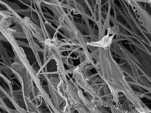
36 Effects of Protein Concentration on the Structures of Freeze-Drying Matrices Morphologies of Protein Matrices (Soy Protein, Keratin from Chicken Feather and Wool) under Different Protein Concentrations Soy Protein Protein Concentration Magnification X100 Magnification X % 0.25%

37 25 0.1% 0.075% 0.05%
.")

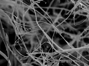
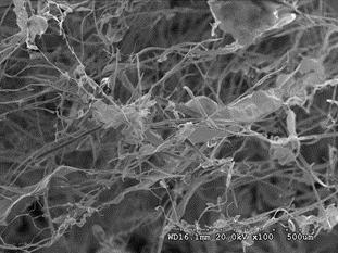
38 % Figure 8. Morphologies of soy protein matrices under different protein concentrations (SEM). Soy protein matrices were freeze dried at different protein concentrations of 0.5 wt. %, 0.25 wt. %, 0.1 wt. %, wt. %, 0.05 wt. %, wt. % ( Magnification : Left, 100x; Right, 350x). Figure 8 shows that the concentration of the soy protein solution influenced the structures of freeze-dried matrices. At 0.5 wt. % protein concentration, the matrix formed film-like structures with no fiber in it. At 0.25 wt. % protein concentration still no fiber formed, but film-like structures became smaller and were films at 0.5 wt. % concentration divided into several small pieces in length direction. This trend was more pronounced with decreasing protein concentrations as the film structures disappeared and fibers formed. At below wt. % protein concentration, most of the structures were fibrous, and as protein concentration lowered, fibers became uniform and finer. At wt. % protein concentration, the fibers were three-dimensionally interconnected with high porosity.


39 27 Keratin from Chicken Feather Protein Concentration Magnification X100 Magnification X % 0.25% 0.1%


.")


40 % 0.05% 0.025% Figure 9. Morphologies of chicken feather keratin matrices under different protein concentrations (SEM). Chicken feather protein matrices were freeze dried at different protein concentrations of 0.5 wt. %, 0.25 wt. %, 0.1 wt. %, wt. %, 0.05 wt. %, wt. % (Magnification: Left, 100x; Right, 350x)
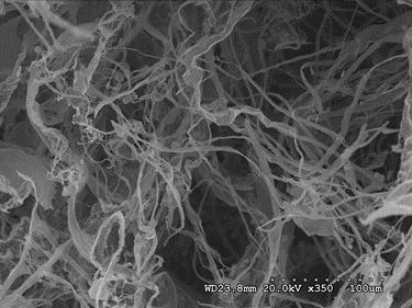
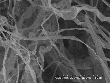
41 29 Figure 9 demonstrated that concentration of chicken feather keratin also affected the formation of structures in the matrices. At 0.5 wt. % protein concentration, all structures were films which were bigger than films at 0.25% wt. protein concentration. At 0.1% wt. protein concentration, fiber structures started to form along with films; and at 0.075% wt. % chicken feather keratin concentration, most of the structures were fibers. As the protein concentration lowers, fibers became finer and more uniform.


42 30 Keratin from Wool Protein Concentration Magnification X100 Magnification X % 0.25% 0.1%


.")


43 % 0.05% 0.025% Figure 10. Morphologies of wool keratin matrices under different protein concentrations (SEM). Wool protein matrices were freeze dried at different protein concentrations of 0.5 wt. %, 0.25 wt. %, 0.1 wt. %, wt. %, 0.05 wt. %, wt. % (Magnification :Left, 100x; Right, 350x).
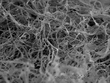
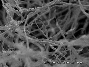
44 32 As shown in Figure 10, morphologies of wool protein matrices also showed the same trend with respect to structural changes as observed for soy protein and chicken feather keratin as its protein concentration was varied. At 0.5 wt. % and 0.25 wt. % wool protein concentration, structures of matrices were films. At a 0.1 wt. % protein concentration, most of the structures were fibers, and fibers became finer and uniform with lower protein concentrations. Fibers were easily observed at protein concentration from 0.1 wt. %.
45 Diameter (µm) Diameters of Fibers from Matrices (Soy protein, Keratin from Chicken Feather and Wool) under Different Protein Concentrations % 0.075% 0.050% 0.025% Protein concentration soy protein Keratin from chicken feather Keratin from wool Figure 11. Diameters of fibers from proteins (soy protein, keratin from chicken feather and wool) freeze-dried matrices formed under different protein concentrations
46 34 As shown in the Figure 11, protein concentration had a great effect on the thickness of fibers from protein matrices. No fiber formed at protein concentrations greater than 0.1 wt. %. Fibers from each protein became finer with decreasing of the protein concentration. Diameters of fibers from chicken feather matrices showed the greatest amount of decrease compared to the other two proteins. Diameters of fibers from soy protein matrices decreased slightly from 4.51µm at 0.1 wt. % to 1.80 wt. % at wt. %. Among the three proteins, diameters of wool keratin fibers reached the finest which was about 1.30µm. The large error bars in the chart indicates that the diameters of fibers were not uniform. As the protein concentration decreased, fibers became more uniform; nonetheless the diameters of fibers still had a wide range at low protein concentrations.
 and at low protein concentration (Right) As shown in Figure 8, Figure 9 and Figure 10, structural changes from films to")
47 35 Ice crystal Protein concentration gradient Excluded protein High protein concentration Low protein concentration Figure 12. Schematic diagrams of fiber formation at high protein concentration (Left) and at low protein concentration (Right) As shown in Figure 8, Figure 9 and Figure 10, structural changes from films to fibers and coarse fibers to fine fibers can be observed with continuous decrease in protein concentrations. This demonstrates that protein concentration played an important role in the formation of fibrous structures. The structural changes caused by varying protein concentration may be due to the following. First, when the protein concentration is low in the solution, the number of excluded protein molecules are relatively less than at higher protein concentration. As a result, fiber formation is finer. Second, at low protein concentrations, there is a relatively higher volume of total ice formation and higher compression pressure on the excluded or trapped protein between the ice crystals, leading to the formation of thinner fibers. Third, from the protein concentration gradient aspect, it is also possible that at low protein concentrations, it is easier for protein molecules to move to low protein concentration areas from areas of high protein concentration and in the same direction as ice crystal growth during freezing. The gradient created at a low protein
48 36 concentration may be higher relatively than the gradient created at a high protein concentration leading to the formation of finer fibers at low protein concentration. The schematic diagrams are represented in the Figure 12.

 37 5.4.")


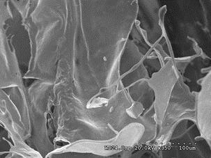
49 5.4 Effects of SDS Concentration on the Structures of Protein Freeze-Drying Matrices (Soy Protein, Keratin from Chicken Feather and Wool) Morphologies of Protein Matrices (Soy protein, Keratin from Chicken Feather and Wool) with Different SDS Concentrations Soy Protein SDS Concentration Magnification 350 X Magnification 1000 X 50 wt. % 100 wt. %


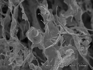
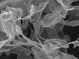
50 wt. % 300 wt. % Figure 13. Morphologies of soy protein matrices under different SDS concentrations (SEM). Soy protein matrices were freeze dried at different SDS concentrations of 50 wt. %, 100 wt. %, 200 wt. %, 300 wt. %, (Magnification: Left, 350x; Right, 1000x) Figure 13 shown the morphologies of soy protein matrices at different SDS concentrations. At 50 wt. % SDS concentration all of the structures were films. At 100 wt. %, there were some fibers formed along with film structure. As the SDS concentration increased, more fibers were generated with less films and beads in the matrices. Structures of the matrices also became clearer with uniform, finer and longer fibers. At 300%, nearly all structures were fibers.


51 39 Keratin from Chicken Feather SDS Concentration Magnification 350X Magnification 1000X 50 wt. % 100 wt. % 200 wt. %

52 wt. % Figure 14. Morphologies of chicken feather keratin matrices under different SDS concentrations (SEM). Matrices were produced at wt. % protein concentration and frozen at -20 Degree Celsius with different SDS concentrations of 50 wt. %, 100 wt. %, 200 wt. %, 300 wt. %, (Magnification: Left, 350x; Right, 1000x) As shown in Figure 14, the structures of chicken feather keratin matrices changed from fuzzy pieces of films into fibers with increasing SDS concentration. At 100 wt. % SDS concentration, fine fibers appeared along with film structures. When SDS concentration increased to 200 wt. %, film structures completely disappeared and coarse fibers dominated the matrix. As the SDS concentration increased to 300 wt. %, more and more fine fibers were fabricated.


53 41 Keratin from Wool SDS Concentration Magnification X350 Magnification X wt. % 100 wt. % 200 wt. %


54 wt. % Figure 15. Morphologies of wool keratin matrices under different SDS concentrations (SEM). Matrices were produced under conditions at wt. % protein concentration and frozen at -20 Degree Celsius with different SDS concentrations of 50 wt. %, 100 wt. %, 200 wt. %, 300 wt. %, (Magnification: Left, 350x; Right, 1000x) Figure 15 demonstrates that SDS concentration had influence on the structural changes of wool keratin matrices. These structural changes were similar with the previous changes observed from matrices made from soy protein and chicken feather keratin. At 50 wt. % and 100 wt. % SDS concentrations, both structures (film and fiber) were present. As SDS concentration increased, more fibers formed relative to at 50 wt. % SDS concentration. At 200 wt. % and 300 wt. % SDS concentrations, no film structure could be observed. There were also no significant changes with further increasing SDS concentration.
55 Diameter (µm) Diameters of Fibers from Protein Matrices (Soy Protein, Keratin from Chicken Feather and Wool) with Different SDS Concentrations Soy protein Keratin from chicken feather Keratin from wool % 100% 200% 300% SDS concentration Figure 16. Diameters of fibers from protein (soy protein, keratin from chicken feather and wool) freeze dried matrices with different SDS concentrations Figure 16 demonstrates that SDS concentration played an important role on the diameter changes of freeze dried protein matrices. Similar diameter changes were observed for the three different proteins. At 50% wt. SDS concentration, fiber was observed only in matrices made from wool keratin. The diameters of soy protein and chicken feather keratin fibers were not measured
56 44 since no fiber was observed at 50 wt. % SDS concentration. The average diameter of wool keratin fibers increased slightly and then decreased again as SDS concentration increased from 100 wt. % 300 wt. %. This pattern also occurred in the diameter changes of fibers with keratin from chicken feather. This result was due to the trend that thin fibers were formed at low SDS concentration alongside films structures; and then as SDS concentration increased coarse fibers were formed without film; further increasing of SDS concentration led to a decrease in the diameters of fibers without film structure. SDS is a surfactant and helps dissolve proteins. When protein concentration and freezing temperature were set as constant, increasing the SDS concentration could allow more protein to be dissolved in the solution. When SDS concentration is low, the partially dissolved protein molecules may form aggregates and are excluded out from solution to form film structures. At the same time, some fully dissolved protein molecules may form fine fibers. This could be the reason that images in Figure 13, Figure 14, and Figure 15 show a mixture of films and fibers at low protein concentration and high freezing temperature. When SDS concentration is high, it is possible that more protein molecules were fully dissolved and distributed in the solution, which led to the production of finer and more uniform fibers. It is also possible that higher SDS concentration (up to a certain level) led to more stable protein molecules and higher ability for fiber extrusion in the solution. This may also contribute to the formation of finer fibers compared to a lower SDS concentration.

 with Different")

57 5.5 Effects of Freezing Temperature on the Structures of Protein Freeze-Drying Matrices Morphologies of Protein Matrices (Soy Protein, Keratin from Chicken Feather and Wool) with Different Freezing Temperatures Soy Protein Freezing Temperatures Low magnification High magnification -20 C 350x 1000x -80 C 350x 1000x
, -80 C (Magnification: Left, 350x;")

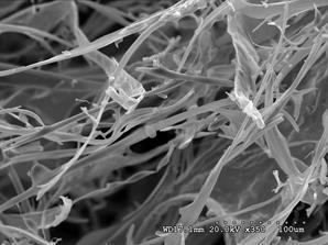
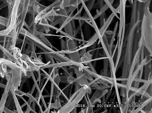
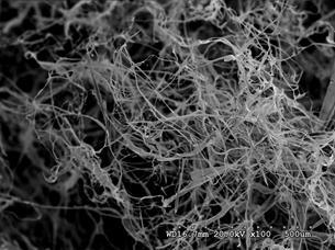
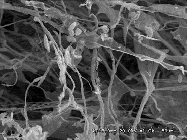
58 C 350x 4500x Figure 17.. Morphologies of soy protein matrices under different freezing temperatures (SEM). Soy protein matrices were freeze dried at different freeze temperatures of -20 C (Magnification: Left, 350x; Right, 1000x), -80 C (Magnification: Left, 350x; Right, 1000x), -196 C (Magnification: Left, 350x; Right, 4500x) As shown in Figure 17, the freezing temperature had a drastic effect on structures of matrices. Fibers became finer with decreasing freezing temperature. At -20 C, fibers were coarse, long and flat; at -80 C, fibers became finer and more uniform, and at -196 C, fibers were short, coiled, and highly interconnected.


59 47 Keratin from Chicken Feather Freezing Temperatures Low magnification High magnification -20 C 350x 1000x -80 C 350x 1000x -196 C 350x 6000x
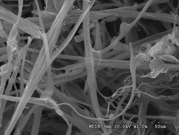
60 48 Figure 18. Morphologies of chicken feather keratin matrices under different freezing temperatures (SEM). Matrices made from chicken feather keratin were freeze dried at different freeze temperatures of -20 C (Left, 350x; Right, 1000x), -80 C (Left, 350x; Right, 1000x), C (Left, 350x; Right, 6000x) As it is shown in Figure 16, at -20 Degree Celsius freezing temperature fibers from chicken feather keratin were coarse and flat. The diameters of fibers decreased as freezing temperature lowered. At -196 Degree Celsius, fibers were fine with diameters on the nano scale and highly interconnected. The structures also had a high degree of orientation.


61 49 Keratin from Wool Freezing Temperatures Low magnification High magnification -20 C 350x 1000x -80 C 350x 1000x -196 C 350x 6000x
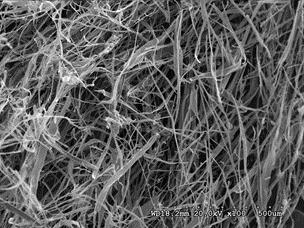
62 50 Figure 19. Morphologies of wool keratin matrices under different freezing temperatures (SEM). Matrices made from keratin from wool were freeze dried at different freeze temperatures of - 20 C (Left, 350x; Right, 1000x), -80 C (Left, 350x; Right, 1000x), -196 C (Left, 350x; Right, 4500x) Figure 19 shows that structural changes on the matrices made from wool keratin followed the same patterns of matrices from chicken feather keratin and soy protein, fibers became finer with decreasing freezing temperature. Fiber structures at -80 Degree Celsius freezing temperature were finer, longer and more uniform than fibers at -20 Degree Celsius.
63 Diameter (µm) Diameters of Fibers from Protein Matrices (Soy Protein, Keratin from Chicken Feather and Wool) with Different Freezing Temperatures 12 Soy protein Keratin from chicken feather Keratin from wool Temperature (Degree Celsius) 0.63 Figure 20. Diameters of fibers from protein (soy protein, keratin from chicken feather and wool) freeze dried matrices controlled by freezing temperature
 with 0.025 wt. % protein concentration and 300 wt. % SDS concentration, there were no film structures observed in the matrices.")

64 52 As it shown in figure 20, temperature had a great effect on diameters of fibers. Fibers became finer with decreasing freezing temperature. At all of these freezing temperatures (-20 C, - 80 C, -196 C) with wt. % protein concentration and 300 wt. % SDS concentration, there were no film structures observed in the matrices. At -20 C freezing temperature diameters of fibers from wool keratin were at 5.69µm on average and diameters of fibers from keratin from chicken feather and soy protein were around 3.5µm. At -80 C, diameters of fibers from those three proteins were around 1.5µm. At -196 C freezing temperature diameters of fibers from the matrices made from three different proteins were all fine which was a jump to the nano scale from the micro scale and were similar to the diameters of the natural collagen fibrils in ECM (50 to 500nm) (Kumar A, 2013). Notably, diameters of fibers of soy protein matrices reached to nearly 0.39µm. High freezing temperature Low freezing temperature Figure 21. Schematic diagram of fiber formation affected by freezing temperature
PRINCIPLES AND PRACTICE OF TISSUE ENGNEERING:
 Harvard-MIT Division of Health Sciences and Technology HST.535: Principles and Practice of Tissue Engineering Instructor: Myron Spector Massachusetts Institute of Technology Harvard Medical School Brigham
Slurry concentration [Vol.%]
![Slurry concentration [Vol.%]](/thumbs/87/96536965.jpg "Slurry concentration [Vol.%]") 6. Discussions 6.1 Discussions of rheological properties on the starting slurries and the dependence on porosity as well as the pore size distribution The analysis performed in the previous section (especially
6. Discussions 6.1 Discussions of rheological properties on the starting slurries and the dependence on porosity as well as the pore size distribution The analysis performed in the previous section (especially
Prof. Steven S. Saliterman. Department of Biomedical Engineering, University of Minnesota
 Department of Biomedical Engineering, University of Minnesota http://saliterman.umn.edu/ Mimicking the fibrillar structure of the extracellular matrix is important for scaffolds. Clinical trails to date
Swelling Behavior Study of γ-irradiated Gelatin Hydrogels Prepared in Organic/Aqueous Mixtures
 J. Ind. Eng. Chem., Vol. 13, No. 6, (2007) 997-1001 Swelling Behavior Study of γ-irradiated Gelatin Hydrogels Prepared in Organic/Aqueous Mixtures Junhwa Shin, Youn Mook Lim, Joon-Pyo Jeun, and Young Chang
Artificial blood vessels
 Artificial blood vessels S. Swaminathan Director Centre for Nanotechnology & Advanced Biomaterials School of Chemical & Biotechnology SASTRA University Thanjavur 613 401 Tamil Nadu Joint Initiative of
Ceramic and glass technology
 1 Row materials preperation Plastic Raw materials preperation Solid raw materials preperation Aging wet milling mastication Mixing seving Grain size reduction Milling Crushing Very fine milling Fine milling
POLY(LACTIC ACID)/HYDROXYAPATITE COMPOSITE FIBRES FOR 3D OSTEOCONDUCTIVE WOVEN SCAFFOLDS
/HYDROXYAPATITE COMPOSITE FIBRES FOR 3D OSTEOCONDUCTIVE WOVEN SCAFFOLDS") ECCM15-15 TH EUROPEAN CONFERENCE ON COMPOSITE MATERIALS, Venice, Italy, 24-28 June 212 POLY(LACTIC ACID)/HYDROXYAPATITE COMPOSITE FIBRES FOR 3D OSTEOCONDUCTIVE WOVEN SCAFFOLDS M. Persson 1,2*, S-W. Cho
ECCM15-15 TH EUROPEAN CONFERENCE ON COMPOSITE MATERIALS, Venice, Italy, 24-28 June 212 POLY(LACTIC ACID)/HYDROXYAPATITE COMPOSITE FIBRES FOR 3D OSTEOCONDUCTIVE WOVEN SCAFFOLDS M. Persson 1,2*, S-W. Cho
Polymeric hydrogels are of special importance in polymeric biomaterials because of
 POLYMERIC HYDROGELS Polymeric hydrogels are of special importance in polymeric biomaterials because of their favorable biocompatibility. Hydrogels are cross-linked macromolecular networks formed by hydrophilic
Fabrication of bone substitute material by Rapid Prototyping
 Fabrication of bone substitute material by Rapid Prototyping A. Ott, J. Heinzl, D. Janitza, R. Pelzer Lehrstuhl für Feingerätebau und Mikrotechnik, Technische Universität München Abstract: Bone tissue
CHAPTER 4 LANGMUIR FILMS AT THE AIR/WATER INTERFACE
 CHAPTER 4 GROWTH OF POLY(ε-CAPROLACTONE) CRYSTALS IN LANGMUIR FILMS AT THE AIR/WATER INTERFACE Reproduced with permission from: Li, B.; Wu, Y.; Liu, M.; Esker, A. R. Brewster Angle Microscopy Study of
Bioreactors in tissue engineering
 Bioreactors in tissue engineering S. Swaminathan Director Centre for Nanotechnology & Advanced Biomaterials School of Chemical & Biotechnology SASTRA University Thanjavur 613 401 Tamil Nadu Joint Initiative
Electrospun Plant Protein Scaffolds with Fibers Oriented Randomly and Evenly in Three- Dimensions for Soft Tissue Engineering Applications
 University of Nebraska - Lincoln DigitalCommons@University of Nebraska - Lincoln Textiles, Merchandising and Fashion Design: Dissertations, Theses, & Student Research Textiles, Merchandising and Fashion
INFLUENCE OF STRUCTURAL ANISOTROPY ON COMPRESSIVE FRACTURE PROPERTIES OF HYDROSTATIC-PRESSURE-EXTRUSION-MOLDED HAP/PLLA COMPOSITE
 18 TH INTERNATIONAL CONFERENCE ON COMPOSITE MATERIALS INFLUENCE OF STRUCTURAL ANISOTROPY ON COMPRESSIVE FRACTURE PROPERTIES OF HYDROSTATIC-PRESSURE-EXTRUSION-MOLDED HAP/PLLA COMPOSITE M. Tanaka 1 *, Y.
Module 13: Soft Lithography. Lecture 19: Soft Lithography 2
 Module 13: Soft Lithography Lecture 19: Soft Lithography 2 1 In the previous lecture we have introduced the concept of Soft Lithography and discussed three of the methods, which are Replica Molding, Micro
Pittsburgh Tissue Engineering Initiative Annual Progress Report: 2011 Formula Grant
 Pittsburgh Tissue Engineering Initiative Annual Progress Report: 2011 Formula Grant Reporting Period July 1, 2012 December 31, 2012 Formula Grant Overview The Pittsburgh Tissue Engineering Initiative received
SIZE EFFECTS OF SIC PARTICLES ON MECHNICAL PROPERTIES OF CAST CARBON NANOFIBERS REINFORCED AZ91 MAGNESIUM COMPOSITES
 THE 19 TH INTERNATIONAL CONFERENCE ON COMPOSITE MATERIALS SIZE EFFECTS OF SIC PARTICLES ON MECHNICAL PROPERTIES OF CAST CARBON NANOFIBERS REINFORCED AZ91 MAGNESIUM COMPOSITES S.-K. Lee 1, S.-B. Lee 1*,
3D MICRO-NANO FIBROUS SCAFFOLD PREPARED BY MELTBLOWN IN COMBINATION WITH ELECTROSPINNING FOR THE BONE TISSUE ENGENEERING
 3D MICRO-NANO FIBROUS SCAFFOLD PREPARED BY MELTBLOWN IN COMBINATION WITH ELECTROSPINNING FOR THE BONE TISSUE ENGENEERING Jakub ERBEN a, Kateřina PILAŘOVÁ a, Filip SANETRNÍK a, Jiří CHVOJKA a, Věra JENČOVÁ
BEH.462/3.962J Molecular Principles of Biomaterials Spring 2003
 Lecture 6: Biodegradable Polymers for Tissue Engineering Last time: Today: enzymatic degradation of solid polymers Engineering biological recognition of polymers Designing polymers for tissue engineering
Effect of Target Shapes on Distribution of Polyacrylonitrile Nanofibers Prepared by Electrospinning Process
 109 Effect of Target Shapes on Distribution of Polyacrylonitrile Nanofibers Prepared by Electrospinning Process Bussarin Ksapabutr *, Chaowat Waikru and Manop Panapoy Department of Materials Science and
A Novel Extrusion Microns Embossing Method of Polymer Film
 Modern Mechanical Engineering, 2012, 2, 35-40 http://dx.doi.org/10.4236/mme.2012.22005 Published Online May 2012 (http://www.scirp.org/journal/mme) A Novel Extrusion Microns Embossing Method of Polymer
Development of Advanced Structural Foam Injection Molding. Kye Kim. A thesis submitted in partial fulfillment of the requirements for the degree of
 Development of Advanced Structural Foam Injection Molding Kye Kim A thesis submitted in partial fulfillment of the requirements for the degree of BACHELOR OF APPLIED SCIENCE Supervisor: Park, C.B. Department
Enhancement of connectivity and flux pinning in MgB2 superconducting bulks and wires
 University of Wollongong Research Online University of Wollongong Thesis Collection 1954-2016 University of Wollongong Thesis Collections 2009 Enhancement of connectivity and flux pinning in MgB2 superconducting
Thermoresponsive Membranes from Electrospun. Mats with Switchable Wettability for Efficient
 Thermoresponsive Membranes from Electrospun Mats with Switchable Wettability for Efficient Oil/Water Separations Yan Liu, a,b Sinem Tas, b Kaihuan Zhang, b, Wiebe M. de Vos, c Jinghong Ma, a,* and G. Julius
Mater. Res. Soc. Symp. Proc. Vol Materials Research Society
 Mater. Res. Soc. Symp. Proc. Vol. 940 2006 Materials Research Society 0940-P13-12 A Novel Fabrication Technique for Developing Metal Nanodroplet Arrays Christopher Edgar, Chad Johns, and M. Saif Islam
Technological aspects of Encapsulation via Melt Extrusion Technology
 Technological aspects of Encapsulation via Melt Extrusion Technology ChemSource Symposium 27-28 June Amsterdam Gülden Yılmaz, WUR, Biobased Products Encapsulation Encapsulation is a commonly applied technology
Synthesis and Characterization of Biodegradable Hemostat Gelatin Sponge for Surgery Application
 R Iranian Journal of Pharmaceutical Sciences Summer 2008: 4(3): 193-200 www.ijps.ir Original Article Synthesis and Characterization of Biodegradable Hemostat Gelatin Sponge for Surgery Application Rana
Silver Diffusion Bonding and Layer Transfer of Lithium Niobate to Silicon
 Chapter 5 Silver Diffusion Bonding and Layer Transfer of Lithium Niobate to Silicon 5.1 Introduction In this chapter, we discuss a method of metallic bonding between two deposited silver layers. A diffusion
White Paper: Textile Engineered Tissue Scaffolds Offer Advances in Hollow Organ Regenerations. Peter D. Gabriele Director, Emerging Technology
 White Paper: Textile Engineered Tissue Scaffolds Offer Advances in Hollow Organ Regenerations Peter D. Gabriele Director, Emerging Technology Regenerative medicine (RM) holds the potential to address some
2. Precision Extrusion Deposition Previous research has focused on Fuse Deposition Modeling (FDM) for the fabrication of
 for the fabrication of") PRECISION EXTRUSION DEPOSITION OF POLYCAPROLACTONE/ HYDROXYAPATITE TISSUE SCAFFOLDS L. Shor, S. Güçeri, W. Sun Laboratory for Computer-Aided Tissue Engineering Department of Mechanical Engineering and
PRECISION EXTRUSION DEPOSITION OF POLYCAPROLACTONE/ HYDROXYAPATITE TISSUE SCAFFOLDS L. Shor, S. Güçeri, W. Sun Laboratory for Computer-Aided Tissue Engineering Department of Mechanical Engineering and
Influence of Drying Temperature Profile on a Multi-Layer Photographic System
 Influence of Drying Temperature Profile on a Multi-Layer Photographic System Fariza B. Hasan, Warren J. Dillman, Daniel D. Huang and Chun-Sheng Ko Film Imaging Research and Development, Polaroid Corporation,
Studies on the Effect of Molecular Weight on the Degradation Rate of Biodegradable Polymer Membrane
 , pp.390-394 http://dx.doi.org/10.14257/astl.2015. Studies on the Effect of Molecular Weight on the Degradation Rate of Biodegradable Polymer Membrane Yuying Xie 1, Jong-soon Park 2, Soon-kook Kang 1,1
Chondrogenic Differentiation of hmscs on PCL Nanofibers
 Chondrogenic Differentiation of hmscs on PCL Nanofibers Winnie Kuo University of California, Berkeley Final Presentation for NSF-REU at UIC August 3, 2006 Advisors: Prof. Cho, Prof. Megaridis, Joel Wise
Micro-CT based local strain analysis of porous materials: potential for industrial applications
 Micro-CT based local strain analysis of porous materials: potential for industrial applications G. Pyka 1, M. Speirs 2, E. Van de Casteele 1, B. Alpert 1, M. Wevers 1, 1 Department of Materials Engineering,
Design of alumina bodies with directional porosity by a freeze-casting method C. Tallón, R. Moreno and M. I. Nieto
 Design of alumina bodies with directional porosity by a freeze-casting method C. Tallón, and M. I. Nieto Institute of Ceramics and Glass, CSIC, Madrid, Spain INTRODUCTION MANUFACTURE OF POROUS MATERIALS
Fabrication and thermal properties of Al 2 TiO 5 /Al 2 O 3 composites
 Materials Science-Poland, Vol. 28, No. 3, 2010 Fabrication and thermal properties of Al 2 TiO 5 /Al 2 O 3 composites M. LI, F. CHEN, Q. SHEN *, L. ZHANG State Key Lab of Advanced Technology for Materials
Multi-walled carbon nanotubes mixed EAPap material for smart materials
 Multi-walled carbon nanotubes mixed EAPap material for smart materials Sungryul Yun, Niangui Wang, Sangdong Jang and Jaehwan Kim * Creative Research Center for EAPap Actuator, Mechanical Engineering Department,
Ceramics, Glasses, and Glass-Ceramics
 Ceramics, Glasses, and Glass-Ceramics Ceramics, Glasses, and Glass-Ceramics include a broad range of inorganic/nonmetallic compositions. Eyeglasses Diagnostic instruments Thermometers Tissue culture flasks
Growth of Micro-Ikebana on a Floating Substrate: A Method to Monitor Local Supersaturation Levels
 Electronic Supplementary Material (ESI) for Physical Chemistry Chemical Physics. This journal is the Owner Societies 2015 Supporting Information Growth of Micro-Ikebana on a Floating Substrate: A Method
Lecture Outline. History. Purpose? Func:on of Bioscaffolds. Extracellular Matrix (ECM) 12/08/15
 12/08/15") Associate Professor Rod Dilley Dr Rob Marano Ear Sciences Centre School of Surgery Harry Perkins Research Building 4 th Floor Lecture Outline History Purpose Functions Properties Approaches to bioscaffold
Associate Professor Rod Dilley Dr Rob Marano Ear Sciences Centre School of Surgery Harry Perkins Research Building 4 th Floor Lecture Outline History Purpose Functions Properties Approaches to bioscaffold
INVESTIGATION OF HIGHLY POROUS POLY(Ε-CAPROLACTONE)
") szerzoi_jav_005_036.qxd 2008.06.20. 16:00 Page 30 INVESTIGATION OF HIGHLY POROUS POLY(Ε-CAPROLACTONE) SCAFFOLDS László Oláh 1, Lajos Borbás 2, Tibor Czigány 3 1 Polymer Competence Center Leoben GmbH 2
szerzoi_jav_005_036.qxd 2008.06.20. 16:00 Page 30 INVESTIGATION OF HIGHLY POROUS POLY(Ε-CAPROLACTONE) SCAFFOLDS László Oláh 1, Lajos Borbás 2, Tibor Czigány 3 1 Polymer Competence Center Leoben GmbH 2
3D Cell Culture Product Intro. Bio-Byblos Biomedical
 3D Cell Culture Product Intro Bio-Byblos Biomedical Rundown Product Intro Cellusponge Series Go Matrix Applications Upcoming Products Degradable series Cellusponge CB series Cell Alignment plate Vivoalign
A Belt-like superfine film fabricated by bubble-electrospinning Hao Dou 1,a, Bao-qi Zuo 1
 Advanced Materials Research Online: 2013-11-21 ISSN: 1662-8985, Vol. 843, pp 82-85 doi:10.4028/www.scientific.net/amr.843.82 2014 Trans Tech Publications, Switzerland A Belt-like superfine film fabricated
Controlled Nanoporosity of Organic Aerogels by Dispersing Clay Platelets
 Controlled Nanoporosity of Organic Aerogels by Dispersing Clay Platelets Kwang Hee Kim, Sangho Park, Sungwoo Hwang and Myung-D. Cho* Materials Research Center, Samsung Advanced Institute of Technology,
3.051J/20.340J Problem Set 1 Solutions
 1 1. (12 pts) Bone tissue engineering generally involves the implantation of a synthetic or biologically derived material that upon implantation allows for bone in-growth and eventual replacement. In a
Mechanical performance of bacterial cellulose nanofibre-reinforced epoxy composites
 High Performance Structure and Materials VI 379 Mechanical performance of bacterial cellulose nanofibre-reinforced epoxy composites H. Takagi1, A. N. Nakagaito1 & K. Uchida2 1 2 Institute of Technology
Tissue Engineering: The art of growing body parts. Robby Bowles, Ph.D Cornell University
 Tissue Engineering: The art of growing body parts Robby Bowles, Ph.D Cornell University What is Tissue Engineering? What is Tissue Engineering? TE is an interdisciplinary field that applies the principles
Impact Strength and Physical Properties of Geopolymer Composites Reinforced with Bagasse Cellulose Fibers
 Impact Strength and Physical Properties of Geopolymer Composites Reinforced with Bagasse Cellulose Fibers *Darunee Wattanasiriwech 1), Tawanporn Munmueangkham 2), and Suthee Wattanasiriwech 3) 1), 2),
Pittsburgh Tissue Engineering Initiative Annual Progress Report: 2010 Formula Grant
 Pittsburgh Tissue Engineering Initiative Annual Progress Report: 2010 Formula Grant Reporting Period July 1, 2011 December 31, 2011 Formula Grant Overview The Pittsburgh Tissue Engineering Initiative,
ENCHANCEMENT OF MECHANICAL PROPERTIES OF CAST NANO CABONS REINFORCED A356 ALUMINIUM MATRIX COMPOSITES
 THE 19 TH INTERNATIONAL CONFERENCE ON COMPOSITE MATERIALS ENCHANCEMENT OF MECHANICAL PROPERTIES OF CAST NANO CABONS REINFORCED A356 ALUMINIUM MATRIX COMPOSITES S.-B. Lee 1*, J.-W. Yi 1, B.M. Jung 1, and
applications J.C. Huang 1, J.S.C. Jang 2, C.H. Lin 1, C.H. Chen 3, C.H. Huang 1, R.F. Chuang 1 National Sun Yat-Sen University
 Ti and Ta based metallic glasses for biomedical applications J.C. Huang 1, J.S.C. Jang 2, C.H. Lin 1, C.H. Chen 3, C.H. Huang 1, R.F. Chuang 1 1 National Sun Yat-Sen University 2 National Central University
Regenerez : A Next-Generation Material for Functional Bioresorbable Coatings. by Carissa Smoot and Jeremy Harris, Ph.D, Secant Medical, Inc.
 Regenerez : A Next-Generation Material for Functional Bioresorbable Coatings by Carissa Smoot and Jeremy Harris, Ph.D, Secant Medical, Inc. Coatings consisting of natural and synthetic origin play an important
PREPARATION AND PROPERTIES OF POROUS ALUMINA CERAMIC PRODUCED BY AN EXTRUSION PROCESS
 Suranaree J. Sci. Technol. Vol. 21 No. 1; January - March 2014 41 PREPARATION AND PROPERTIES OF POROUS ALUMINA CERAMIC PRODUCED BY AN EXTRUSION PROCESS Thanakorn Wasanapiarnpong 1,2*, Yolnapa Ngoenngam
Centrifugal spinning of nanofiber webs - A parameter study of a novel spinning process
 Centrifugal spinning of nanofiber webs - A parameter study of a novel spinning process Jonas Engström Senior scientist at Swerea IVF. Finished his PhD in 2006 with a thesis titled Functional compolymers
New approach for porous materials obtaining using centrifugal casting
 IOP Conference Series: Materials Science and Engineering PAPER OPEN ACCESS New approach for porous materials obtaining using centrifugal casting To cite this article: O Bltescu et al 2015 IOP Conf. Ser.:
FABRICATION OF 316L STAINLESS STEEL FOAMS VIA POWDER METALLURGY TECHNIQUE
 FABRICATION OF 316L STAINLESS STEEL FOAMS VIA POWDER METALLURGY TECHNIQUE Z. Abdullah, S. Ahmad, M. F. M. Rafter and N. S. A. Manaf Faculty of Mechanical and Manufacturing Engineering, Universiti Tun Hussein
CRYSTALLOGRAPHIC MATCHING EFFECT IN SELF-INDUCED NANOHYBRID SHISH-KEBAB STRUCTURE OF POLY E-CAPROLACTONE)
") CRYSTALLOGRAPHIC MATCHING EFFECT IN SELF-INDUCED NANOHYBRID SHISH-KEBAB STRUCTURE OF POLY E-CAPROLACTONE) Xiaofeng Wang, 1,2 Yanhong Gao, 2,3 Yiyang Xu, 1,2 Xuyan Li, 1,2 Lin Jiang, 2,3 Qian Li, 1,2* 1
CRYSTALLOGRAPHIC MATCHING EFFECT IN SELF-INDUCED NANOHYBRID SHISH-KEBAB STRUCTURE OF POLY E-CAPROLACTONE) Xiaofeng Wang, 1,2 Yanhong Gao, 2,3 Yiyang Xu, 1,2 Xuyan Li, 1,2 Lin Jiang, 2,3 Qian Li, 1,2* 1
Course Handbook MSc in Bioengineering Tissue Engineering Specialisation
 Course Handbook 2013-2014 MSc in Bioengineering Tissue Engineering Specialisation 1 Course Objectives & Learning Outcomes This programme aims to give a sound and broad basis in tissue engineering. In particular,
5. INVESTIGATION OF POROSITY IN THE PASTILLES
 5. INVESTIGATION OF POROSITY IN THE PASTILLES 5.1. Introduction Many different types of controlled dosage forms have been developed to improve clinical efficiency of drug and patient compliance. In vivo
The research work highlights the development and evaluation of. bioavailability of drugs. The buccal route can bypass the first-pass
 212 9. Summary, conclusion and recommendation 9.1 Summary and conclusion The research work highlights the development and evaluation of novel transbuccal drug antagonist of Famotidine. route have a rapid
Development of Elastic Polylactic Acid Material Using Electron Beam Radiation
 ELECTRONICS Development of Elastic Polylactic Acid Material Using Electron Beam Radiation Shinichi KANAZAWA Sumitomo Electric Fine Polymer has developed a technology for fabricating a brand new elastic
Methods of manufacture
 1 Methods of manufacture For Ceramics (see (b)) Crush raw materials Shape the crushed raw materials (various means) Dry & fire Apply finishing operations, as needed; to achieve required dimensional tolerances
INFLUENCE OF THE SURFACE MORPHOLOGY AT SPECIFIC SURFACE AREA OF MICROFIBRES MADE FROM POLY (L-LACTIDE) MACAJOVÁ Eva
 MACAJOVÁ Eva") INFLUENCE OF THE SURFACE MORPHOLOGY AT SPECIFIC SURFACE AREA OF MICROFIBRES MADE FROM POLY (L-LACTIDE) MACAJOVÁ Eva Department of Material Science, Technical University of Liberec, Liberec, Czech Republic,
INFLUENCE OF THE SURFACE MORPHOLOGY AT SPECIFIC SURFACE AREA OF MICROFIBRES MADE FROM POLY (L-LACTIDE) MACAJOVÁ Eva Department of Material Science, Technical University of Liberec, Liberec, Czech Republic,
AEROWOOD Wood-based aerogels
 http://blogs.helsinki.fi/aerowood-project Bodo Saake, University of Hamburg, Centre for Wood Science / WoodWisdom-Net Seminar Edinburgh 4-5 April 2017 AEROWOOD Wood-based aerogels DIO YOU What and why?
COMPARISON OF NANOPOROUS SCAFFOLDS MANUFACTURED BY ELECTROSPINNING AND NANOFIBRILLAR COMPOSITE CONCEPT
 18 TH INTERNATIONAL CONFERENCE ON COMPOSITE MATERIALS COMPARISON OF NANOPOROUS SCAFFOLDS MANUFACTURED BY ELECTROSPINNING AND NANOFIBRILLAR COMPOSITE CONCEPT S. T. C. Lin 1 *, D. Bhattacharyya 1, S. Fakirov
STUDY ON CHEMICAL TREATMENT OF CELLULOSE FIBER TO IMPROVE HEAT RESISTANCE AND THE MECHANICAL PROPERTY OF COMPOSITE MATERIALS USING TREATED FIBER
 THE 19TH INTERNATIONAL CONFERENCE ON COMPOSITE MATERIALS STUDY ON CHEMICAL TREATMENT OF CELLULOSE FIBER TO IMPROVE HEAT RESISTANCE AND THE MECHANICAL PROPERTY OF COMPOSITE MATERIALS USING TREATED FIBER
Lecture 5: 8/31. CHAPTER 5 Techniques in Protein Biochemistry
 Lecture 5: 8/31 CHAPTER 5 Techniques in Protein Biochemistry Chapter 5 Outline The proteome is the entire set of proteins expressed and modified by a cell under a particular set of biochemical conditions.
Evaluation of Sodium Titanate Coating on Titanium by Sol-Gel Method in vitro
 Key Engineering Materials Online: 2007-02-15 ISSN: 1662-9795, Vols. 330-332, pp 777-780 doi:10.4028/www.scientific.net/kem.330-332.777 2007 Trans Tech Publications, Switzerland Evaluation of Sodium Titanate
Methods in Bioengineering: 3D Tissue Engineering
 Methods in Bioengineering: 3D Tissue Engineering Berthiaume, Francois ISBN-13: 9781596934580 Table of Contents Preface Chapter 1. Chemical Modification of Porous Scaffolds Using Plasma Polymers 1.1. Introduction
Synthesis and Characterization of α-alumina Membrane Support and Effects of Binders
 Synthesis and Characterization of α-alumina Membrane Support and Effects of Binders M. Khalili a,*, S. Sabbaghi a, H. Daneshmand a, M.M. Zerafat b a Faculty of Nanotechnology, Nano Chemical Engineering
Effects of TiO2 Contents on HA/TiO2 Composite Coating by Electrophoretic Deposition Lei Zhao, Huiping Shaoa, Hang Zheng
 International Conference on Manufacturing Science and Engineering (ICMSE 2015) Effects of TiO2 Contents on HA/TiO2 Composite Coating by Electrophoretic Deposition Lei Zhao, Huiping Shaoa, Hang Zheng Institute
MSE 352 Engineering Ceramics II
 Kwame Nkrumah University of Science & Technology, Kumasi, Ghana MSE 352 Engineering Ceramics II Ing. Anthony Andrews (PhD) Department of Materials Engineering Faculty of Mechanical and Chemical Engineering
magnetic nanoparticles, part 1. synthetic methods: from mechanochemistry to biomimetics
 magnetic nanoparticles, part 1. synthetic methods: from mechanochemistry to biomimetics Tanya Prozorov, Ph.D. US DOE Ames Laboratory e mail: tprozoro@ameslab.gov 1 outline some definitions what happens
SCIENTIFIC ANALYSIS AND ENDORSEMENT OF NITTA CASINGS COLLAGEN GEL
 SCIENTIFIC ANALYSIS AND ENDORSEMENT OF NITTA CASINGS COLLAGEN GEL 12/26/2017 For Nitta Casings TABLE OF CONTENTS About Dr. Silvia Minardi 2 Background on Collagen.. 3 Analysis of NITTA GEL. 3 Endorsement
LYOPHILIZATION. Introduction to Freeze-Drying Third of Four Lectures. Freezing, Annealing, Primary, and Secondary Drying. J. Jeff Schwegman, Ph.D.
 LYOPHILIZATION Introduction to Freeze-Drying Third of Four Lectures Freezing, Annealing, Primary, and Secondary Drying J. Jeff Schwegman, Ph.D. AB BioTechnologies P.O. Box 1430 Bloomington, Indiana, 47402
Cellulose- and Chitin-Based Coatings and Films. Carson Meredith Professor Chemical & Biomolecular Engineering Georgia Tech Atlanta, GA
 Cellulose- and Chitin-Based Coatings and Films Carson Meredith Professor Chemical & Biomolecular Engineering Georgia Tech Atlanta, GA 1 One Motivation - Packaging 1.3 billion tons of food, 1/3 of the world
Supporting Information. Carbon Welding by Ultrafast Joule Heating
 Supporting Information Carbon Welding by Ultrafast Joule Heating Yonggang Yao, 1,(a) Kun Fu, 1,(a) Shuze Zhu, 2 Jiaqi Dai, 1 Yanbin Wang, 1 Glenn Pastel, 1 Yanan Chen, 1 Tian Li, 1 Chengwei Wang, 1 Teng
DRAWING - THE PRODUCTION OF INDIVIDUAL NANOFIBERS BY EXPERIMENTAL METHOD. Studentská 2, Liberec, Czech Republic,
 DRAWING - THE PRODUCTION OF INDIVIDUAL NANOFIBERS BY EXPERIMENTAL METHOD Jana BAJÁKOVÁ a, Jiří CHALOUPEK a, David LUKÁŠ a, Maxime LACARIN a Technical University of Liberec, Faculty of Textile Engineering,
Fe doped Magnetic Nanodiamonds made by Ion
 Fe doped Magnetic Nanodiamonds made by Ion Implantation ChienHsu Chen a, I.C. Cho b, Hui-Shan Jian c and H. Niu a* a Nuclear Science and Technology Development Center, National Tsing Hua University, HsinChu
ADVANTAGES OF MULTIPARTICULATES (PELLETS):
:") INTRODUCTION: Multiparticulate Drug Delivery Systems (MDDS): The concept of multiple unit dosage form was initially introduced in the early 1950 s.these forms play a major role in the design of solid dosage
INTRODUCTION: Multiparticulate Drug Delivery Systems (MDDS): The concept of multiple unit dosage form was initially introduced in the early 1950 s.these forms play a major role in the design of solid dosage
Nanyang Technological University School of Materials Science & Engineering
 Final Year Project Proposal 1 3D Assembly of Nano/Micro Zirconia Particles for Enhanced Energy Damping Capacity Dr Du Zehui (duzehui@ntu.edu.sg) To develop the best possible method to assemble micro/nano-scale
UConn BMES Meeting #2 (9/28) T R A C K P R E S E N T A T I O N S
 T R A C K P R E S E N T A T I O N S") UConn BMES Meeting #2 (9/28) T R A C K P R E S E N T A T I O N S Concept of Biomedical Engineering Biomedical Engineering is an interdisciplinary application of engineering principals The major is an application
UConn BMES Meeting #2 (9/28) T R A C K P R E S E N T A T I O N S Concept of Biomedical Engineering Biomedical Engineering is an interdisciplinary application of engineering principals The major is an application
BIL 256 Cell and Molecular Biology Lab Spring, Molecular Weight Determination: SDS Electrophoresis
 BIL 256 Cell and Molecular Biology Lab Spring, 2007 Molecular Weight Determination: SDS Electrophoresis Separation of Proteins by Electrophoresis A. Separation by Charge All polypeptide chains contain
ELECTROSPUN NANOFIBER PROCESS CONTROL
 CELLULOSE CHEMISTRY AND TECHNOLOGY Received April 26, 2010 ELECTROSPUN NANOFIBER PROCESS CONTROL University of Guilan, P.O. Box 3756, Rasht, Iran Fiber diameter is an important structural characteristic
Tissue Engineered Medical Products
 WORKSHOP 8 Tissue Organizer: Jeremy J. Rawlinson PhD Speakers: Jack E. Lemons, PhD Lawrence J. Bonassar, PhD Mauro R. Alini, PhD Michael J. Yaszemski, MD, PhD Standards for Tissue J. Lemons, University
CHAPTER 4 CONCLUSIONS AND FUTURE PERSPECTIVES
 CHAPTER 4 CONCLUSIONS AND FUTURE PERSPECTIVES Wound infections are the major challenges in the wound care management. Infection can be either due to microbial attack or due to some diseases. This infection
Fabrication and characterization of nanocellulose aerogel structures
 Tampere University of Technology Fabrication and characterization of nanocellulose aerogel structures Citation Virtanen, J., Janka, M., & Tuukkanen, S. (2017). Fabrication and characterization of nanocellulose
A NANOFIBROUS HYDROGEL FOR BONE TISSUE ENGINEERING
 A NANOFIBROUS HYDROGEL FOR BONE TISSUE ENGINEERING Umadevi Kandalam, PhD Assistant Professor Department of Pediatric Dentistry College of Dental Medicine Nova Southeastern University Fort Lauderdale, Florida
CHARACTERIZATION AND APPLICATION OF COLLAGEN-POLYMER BASED COMPOSITE AS WOUND HEALING MATERIAL
 th ICAMS 2012 4 International Conference on Advanced Materials and Systems CHARACTERIZATION AND APPLICATION OF COLLAGEN-POLYMER BASED COMPOSITE AS WOUND HEALING MATERIAL DENİZ GÜRLER, EYLEM KILIÇ Uşak
DESIGN AND MANUFACTURING OF A SCAFFOLD FOR BIOMEDICAL APPLICATIONS USING ADDITIVE MANUFACTURING
 ISSN: 2250-0138 (Online) DESIGN AND MANUFACTURING OF A SCAFFOLD FOR BIOMEDICAL APPLICATIONS USING ADDITIVE MANUFACTURING L. SIVA RAMA KRISHNA a1, M. KAMAL b, SRIRAM VENKATESH c AND MANMADHACHARY d abc
THE EFFECT OF BIAXIAL ORIENTATION PROCESSING CONDITIONS ON IMMISCIBLE POLYMER BLENDED SHEET
 THE EFFECT OF BIAXIAL ORIENTATION PROCESSING CONDITIONS ON IMMISCIBLE POLYMER BLENDED SHEET Jennifer K. Lynch, Ph.D., Rutgers University Thomas J. Nosker, Ph.D., Rutgers University James D. Idol, Ph.D.,
Characterization of Coatings on Grey Cast Iron Fabricated by Hot-dipping in Pure Al, AlSi11 and AlTi5 Alloys
 A R C H I V E S o f F O U N D R Y E N G I N E E R I N G Published quarterly as the organ of the Foundry Commission of the Polish Academy of Sciences ISSN (1897-3310) Volume 14 Issue 1/2014 85 90 20/1 Characterization
Surface Construction Of Zn Doped Hydroxyapatite/mgf2 Multilayer Coatings For The Biomedical Mg Materials By A Novel Conversion/sol-gel Method
 Surface Construction Of Zn Doped Hydroxyapatite/mgf2 Multilayer Coatings For The Biomedical Mg Materials By A Novel Conversion/sol-gel Method Heng Jui Liu 1, Da Jun Lin 1, Subhaini jakfar 2, Fei Yi Hung
Articular Cartilage Engineering Using Human Mesenchymal Stem Cells and Nanostructured Biomaterials
 Articular Cartilage Engineering Using Human Mesenchymal Stem Cells and Nanostructured Biomaterials REU Participant: Nicole Green 1 Advisors: Joel Wise 2, Dr. Michael Cho 2, Dr. Constantine Megaridis 3
Applying the mutation of Bacillus subtilis and the optimization of feather fermentation medium to improve Keratinase activity
 Advances in Biological Chemistry, 2012, 2, 64-69 http://dx.doi.org/10.4236/abc.2012.21008 Published Online February 2012 (http://www.scirp.org/journal/abc/) ABC Applying the mutation of Bacillus subtilis
Isolation of Protein
 Isolation of Protein Ultra-centrifugation http://irfanchemist.wordpress.com/2009/04/19/isolation-of-protein / Protein solutions of various masses or densities may separated based on the time it takes to
Ceramics, Cracow, Poland
 Chemically and physically functionalized carbon composites a prospective material for tissue treatment S.Blazewicz 1*, E.Stodolak 1, E. Staszkow 2, T.Mikolajczyk 3 1 AGH University of Science and Technology,
Effect of titanium additions to low carbon, low manganese steels on sulphide precipitation
 University of Wollongong Thesis Collections University of Wollongong Thesis Collection University of Wollongong Year 2008 Effect of titanium additions to low carbon, low manganese steels on sulphide precipitation
New Cu-based Bulk Metallic Glasses with High Strength of 2000 MPa
 Materials Science Forum Online: 2004-03-15 ISSN: 1662-9752, Vols. 449-452, pp 945-948 doi:10.4028/www.scientific.net/msf.449-452.945 2004 Trans Tech Publications, Switzerland New Cu-based Bulk Metallic
Tissue Scaffold Engineering by Micro-Stamping
 Tissue Scaffold Engineering by Micro-Stamping Journal: 2013 MRS Fall Meeting Manuscript ID: MRSF13-1626-K05-06 Manuscript Type: Symposium K Date Submitted by the Author: 17-Dec-2013 Complete List of Authors:
The Electrospinning Company
 The Electrospinning Company September 2015 Contact: info@electrospinning.co.uk +44 1235 567276 UK SME Design, develop and manufacture advanced biomaterial scaffolds Sales of product and service R&D collaborations