Reliability Considerations from Flux Residues trapped under Component Terminations
|
|
|
- Abraham Ramsey
- 5 years ago
- Views:
Transcription

1 Reliability Considerations from Flux Residues trapped under Component Terminations Mike Bixenman, DBA, Kyzen Corporation Bruno Tolla, Ph.D., Jennifer Allen, Kyle Loomis, Kester Corp. Kester Kyzen Joint Research Project Originally published in the Proceedings of SMTA International, Rosemont, Il, September 25-September 29, 2016
2 Introduction Problem Statement Purpose Statement Research Hypotheses Test Board DOE Responses Conclusions Outline/Agenda
3 INTRODUCTION
4 Electro-Chemical Failures Smaller form factors present Limitations Obstacles Challenges Time delayed effects Residues trapped under components Can be active Mobilized Metals can migrate

5 Leadless Components Low Standoff gaps + High soldering mass Block flux outgassing channels Residues accumulate and bridge conductors Can still contain solvents and activators Small moisture levels can lead to Leakage currents Dendritic growth Shorts
6 No-Clean Solder Pastes Engineered to render a Benign post soldering residue During reflow Solvents are designed to outgas Activators oxidize and reduce Remaining activators and fluxing by-products Designed to be encapsulated into a resin binder The design is to yield an inert residue
7 PROBLEM STATEMENT
8 Flux Residues under BTCs Several factors that can cause failures Flux outgassing channel is compromised Solvents do not totally evaporate Live residue can be present Polar Hydroscopic Acts as a media for corrosion
9 Failed Devices BTC devices fail due to Dendritic growth under the component termination Location of dendrites correspond to Trapped flux residues Cleaning under BTCs is challenging Residue remaining under the component post cleaning may also be problematic
10 PURPOSE STATEMENT
11 Research Purpose Research the effects of Different solder paste activator packages Cleaning No Cleaning Partial Cleaning Total Cleaning Reflow profiles Ramp-to-Spike Soak
12 RESEARCH HYPOTHESES
13 Research Hypotheses Tested H 1 : Flux residues trapped under the bottom termination create the potential for ion mobilization and current leakage H 2 : Flux activators can be designed to reduce current leakage potential H 3 : Process optimization helps to reduce current leakage as longer profiles promote the conversion of activators into inert residues H 4 : Partial cleaning can expose flux constituents that can increase leakage potential H 5 : Total cleaning reduces current leakage potential
14 TEST BOARD

15 SIR Flux Reliability Test Board A non-standard board design was chosen to place the resistivity sensors for a SIR test under various low standoff devices 1. Board surface finish: OSP 2. Sensor traces: Variable 3. Copper weight: 1oz copper 4. Hole size under QFN: 20 mils or smaller non plated 5. Legend color ink: White 6. Solder mask: LPI, min thickness at the conductor edge = 8μm (0.315 mil) 7. Fiducial: Qty 3, Board thickness: 0.062
16 SIR Flux Reliability Test Board Several low standoff devices were selected to obtain a wide variety of SIR data sets Devices selected were: BGA100 with 0.8mm pitch Resistors 2512, 1210 & 0805 passives QFN44 s and QFN100 s Pin out shown is for the A.S.R., 4 channel B24 connector wiring harness (A,B,C,D) no hard wiring required

17 SIR Flux Reliability Test Board Channel D: To achieve a series of sensors under the BGAs, the board layout complements the internal Daisy Chain of each BGA to form the SIR electrical gap spacings between selected balls under each device


18 SIR Flux Reliability Test Board Channel C: To achieve a series of sensors under the passives, the board has traces under the central body of the 12 devices to form the SIR electrical gap spacings under each device. Paste was deposited on the sensor traces to ensure flux connections between the sensor traces.


19 SIR Flux Reliability Test Board Channel B: To achieve a series of sensors under the QFN44 devices, the board traces form a loop around the central pad terminal and between the loop and the perimeter leads to form the SIR electrical gap spacings.


20 SIR Flux Reliability Test Board Channel A: To achieve a series of sensors under the QFN100 devices, the board traces form a loop around the central pad terminal and between the loop and the perimeter leads to form the SIR electrical gap spacings.
21 DOE


22 SIR Flux Reliability Test Board The IPC SIR test method using the open format B24 pattern directs the user to setup measurement systems to obtain an electrical field strength between the positive and negative traces (gaps) to 5V for 200um of spacing. The table below shows a variety of field strength for the IPC standard boards and the DoE board at different voltage conditions. QFN100 Selected voltage Bias was 8V


23 SIR Test Parameters Test Coupon: Bias: Test Voltage: Kester Flux Reliability Test Board 8 volts 8 volts Temperature: 85 C Humidity: 85% RH Measurement Interval: every 20 minutes at condition Test Duration: 7 Days (168 hours) Temperature is ramped before humidity elevated to avoid reaching the dew point. Inverse applies to the recovery ramp down
24 Reflow Profiles Two different reflow conditions were used with the intent to subject the flux resides to low and high heating conditions Soak Ramp to Spike
25 Cleaning Tool Setup
26 Cleaning Parameters Cleaning Conditions No-Cleaning Partial Cleaning Inline spray-in-air, 2 FPM, 3 min wash Total Cleaning Inline spray-in-air, 0.5 FPM, 10 minute wash Wash Temperature: 65 C Subset of parts where removed during setup to assure partial and total cleaning effects
27 Responses Surface Insulation Resistance Residues Dye Pry Method Ion Chromatography
28 SURFACE INSULATION RESISTANCE

29 SIR Readings obtained A wide variety of readings were obtained across the 96 unique DoE combinations of paste activators, sensors and devices, reflow profiles, and cleaning methods QFN100

30 Cleaning Effects The average logarithmic values based the response of each board A pattern emerged showing the effect of cleaning on the SIR responses QFN100

31 Ramp Reflow Profile


32 Soak Reflow Profile

33 Device Responses Analysis of all the SIR readings data by device show that the QFN100 s have the largest variance in data
34 QFN 100

35 Activator 1 for QFN 100
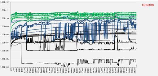
36 ,400 1,860 2,320 2,780 3,240 3,700 4,160 4,620 5,080 5,540 6,000 6,460 6,920 7,380 7,840 8,300 8,760 9,220 9,680 Activator 2 for QFN E+11 1.E+10 1.E+09 1.E+08 1.E+07 1.E+06 1.E+05 1.E+04

37 Activator 3 for QFN 100

38 Activator 4 for QFN 100
39 SIR Results and Discussion The backbone of flux composition Solvents Additives Other types of activators Greater decisive impact on reliability than does Halogen-Free
40 Activators 1, 2, 3, & 4 Activator 1 & 2 Halogen Free Worse reliability performance Activators 3 & 4 Halide activators Failures identified by SIR spikes Characteristic of ECM Activator 3 Halide based activator Interplays between chemical reactions, processing conditions and end-usage environments are thoroughly understood
41 VISUAL RESIDUES

42 QFN 44 Part profile Activator 1 Soak Profile Uncleaned

43 QFN 100 Part Profile Activator 4 Soak Profile Uncleaned

44 QFN 100 Part Profile Activator 4 Soak profile Partial Cleaning

45 QFN 100 & QFN 44 Part Profile Activator 4 Soak profile Total Cleaning
46 ION CHROMATOGRAPHY
47 Not Cleaned Boards Only a few ions exceeded guidelines Nitrate, Nitrite, Sulfate and Potassium Come from the board Not a part of the flux package Flux specific components Chlorides from Activator 4 Bromides from Activator 3 Weak Organic Acids from all activator packages
48 Cleaned Boards Partial and Total Chlorides present in Activator 4 require an extensive cleaning process Bromides show a similar trend Weak organic acid levels Remain stable throughout the test Similar across activator packages Zero halogen fluxes Significant differences in reliability
49 HYPOTHESES TESTED
50 Hypothesis 1 Flux residues trapped under the bottom termination create the potential for ion mobilization and current leakage Accept Data conclusive finds that flux residue trapped under the component has the potential to drop resistance and current leakage
51 Hypothesis 2 Flux activators can be designed to reduce current leakage potential Accept Data conclusively finds that the activator has a significant effect on resistance and current leakage Activator 3 was the safest activator package Should flux residue not be cleaned If flux residue was still present following the cleaning process All activator types had high resistance values and showed no current leakage when parts were totally cleaned
52 Hypothesis 3 Soak reflow profile reduces current leakage as compared to the Ramp-to-Spike profile Reject Interesting finding Some packages are more sensitive to heat treatment than others On QFN 100, soak profile found lower resistivity values when residue was present
53 Hypothesis 4 Partial cleaning can expose flux constituents that can increase leakage potential Undetermined The data finds that partial cleaning be detrimental for some classes of activators More experiments are needed to demonstrate a degradation between uncleaned and partially cleaned conditions
54 Hypothesis 5 Total cleaning reduces current leakage potential Accept The data conclusively finds that total cleaning improves resistance values No SIR fails were detected All activator packages and components types passed when totally cleaned
55 CONCLUSIONS
56 Low Standoff Components Present dramatic impacts on the reliability of the final assembly Customized SIR test board is valuable in testing Solder paste types Cleaning material effectiveness Cleaning equipment Environmental conditions Modeling end use environment Best approach to studying reliability risks
57 Flux compositions Key Finding Broad class of chemicals used in flux activators have different activities and moisture sensitivities Not cleaned and partial cleaned boards can have meaningful risk assessments Thorough cleaning below published guidelines found excellent reliability under all components, regardless of activator package

58 Thank you Mike Bixenman Kyzen Corp. Bruno Tolla, Ph.D. Kester Corp. Jennifer Allen Kester Corp. Kyle Loomis Kester Corp.
59 Acknowledgements Dale Lee from Plexus, for his contribution to the reliability board layout Denis Jean, Product Technology Manager at Kester Chelsea Jewell, Process Development Engineer at KYZEN Corporation to clean test boards. Kevin Soucy, Application Manager at KYZEN Corporation for his help in setting up the machine to run test boards. James Perigen, Chemist at KYZEN Corporation for running the IC analysis on test boards