IC Equipment. Ultrafiltration Manual EN
|
|
|
- Milton Crawford
- 5 years ago
- Views:
Transcription

1 IC Equipment Ultrafiltration Manual EN
2
3 Metrohm AG CH-9101 Herisau Switzerland Phone Fax IC Equipment Ultrafiltration Manual EN zst
4 Teachware Metrohm AG CH-9101 Herisau This documentation is protected by copyright. All rights reserved. Although all the information given in this documentation has been checked with great care, errors cannot be entirely excluded. Should you notice any mistakes please send us your comments using the address given above. Documentation in additional languages can be found on under Literature/Technical documentation.
5 Table of contents Table of contents 1 Introduction Description of the IC equipment for ultrafiltration Mode of operation for ultrafiltration About the documentation Symbols and conventions The ultrafiltration cell Installation Mounting the ultrafiltration cell Installing the ultrafiltration cell Connecting the ultrafiltration cell Deaerating the ultrafiltration cell Handling and maintenance Operation Filtration according to sample types Service life of the filtration membrane Selecting the filtration membrane Maintenance Technical specifications Ultrafiltration cell Filtration membrane Dialysis membrane Accessories Scope of delivery Optional accessories Index 24 IC Equipment for Ultrafiltration III
6 Table of figures Table of figures Figure 1 Ultrafiltration cell Exploded view... 3 Figure 2 Ultrafiltration cell Connectors... 4 Figure 3 Ultrafiltration cell on the Sample Processor... 7 Figure 4 Fastening the ultrafiltration cell in the IC instrument... 8 Figure 5 Connecting the ultrafiltration cell... 9 Figure 6 Injection valve IV IC Equipment for Ultrafiltration
7 1 Introduction 1 Introduction 1.1 Description of the IC equipment for ultrafiltration The IC equipment for ultrafiltration ( ) is used for inline filtration of difficult samples directly before injection. The main component of the equipment is the high-performance ultrafiltration cell which is designed for the filtration of samples requiring special filtration capacity and sample throughput. The two channels of a peristaltic pump are required in addition for conveying the sample and the filtrate. To utilize the IC equipment for ultrafiltration, you will require the following: an IC instrument and a Sample Processor with peristaltic pump and cell holder (recommended combination) or an IC instrument with built-in peristaltic pump and cell holder (e.g. ProfIC Cation Prep 1 ( ) or ProfIC Anion MCS Prep 1 ( )) or an IC instrument with peristaltic pump and the filtration cell holder ( ) for the detector chamber (available as optional accessories) 1.2 Mode of operation for ultrafiltration The peristaltic pump continuously conveys the flow of sample material at a high flow rate through the lower chamber of the ultrafiltration cell, along the filtration membrane and on to the waste container. At the same time, it generates a vacuum in the upper chamber of the ultrafiltration cell which causes the sample solution to be suctioned through the filtration membrane. The filtrate reaches the sample loop and is then injected. Less than 20% of the original solution is removed as filtrate. The remainder flows directly into the waste container. IC Equipment for Ultrafiltration 1


8 1.3 About the documentation 1.3 About the documentation This manual describes the correct assembly and maintenance of the ultrafiltration cell, the installation of the capillary connections that lead to and from the ultrafiltration cell, and the mounting of the holder on both the Sample Processor and the IC instrument. The installation and tubing of the peristaltic pump and the injection valve are not described in this manual. They are to be found in the respective manuals for the IC instrument and/or the Sample Processor. Caution Please read through this documentation carefully before putting the equipment into operation. The documentation contains information and warnings which have to be followed by the user in order to ensure safe operation of the equipment Symbols and conventions The following symbols and styles are used in this documentation: Cross-reference to figure legend The first number refers to the figure number, the second to the instrument part in the figure. Instruction step Carry out these steps in the sequence shown. Warning This symbol draws attention to a possible life hazard or risk of injury. Warning This symbol draws attention to a possible hazard due to electrical current. Warning This symbol draws attention to a possible hazard due to heat or hot instrument parts. Warning This symbol draws attention to a possible biological hazard. 2 IC Equipment for Ultrafiltration
9 1 Introduction Caution This symbol draws attention to a possible damage of instruments or instrument parts. Note This symbol marks additional information and tips. 1.4 The ultrafiltration cell Components of the ultrafiltration cell Figure Ultrafiltration cell Exploded view 1 Upper part of cell 2 Lower part of cell 3 Sealing ring (E ) 4 Filtration membrane ( ) 5 Washer ( ) 6 Screws (V ) for screwing together the upper and lower parts of the cell IC Equipment for Ultrafiltration 3
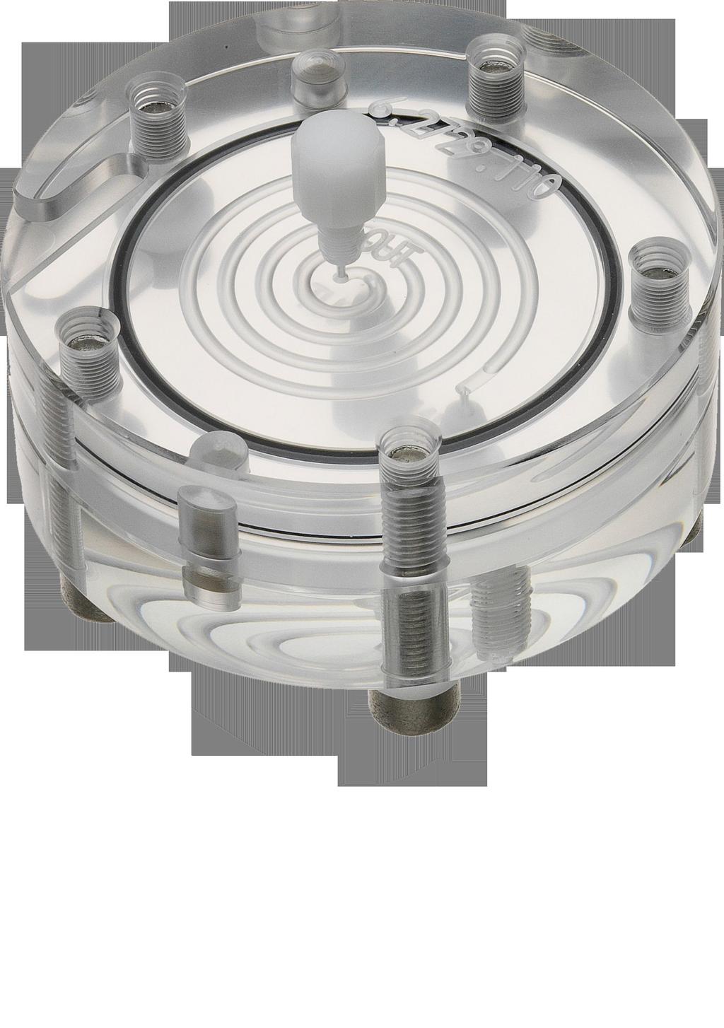
10 1.4 The ultrafiltration cell Connectors of the ultrafiltration cell 1 2 Figure Ultrafiltration cell Connectors 1 Upper part of cell 2 Lower part of cell 3 Filtrate outlet 4 Sample inlet 5 Sample outlet 4 IC Equipment for Ultrafiltration
11 2 Installation 2 Installation This chapter describes the assembly of the ultrafiltration cell, its fastening to the Sample Processor and/or to the IC instrument, and its connection to both the peristaltic pump and the injection valve. Depending on the combination of instruments used, the ultrafiltration cell can be placed at different locations. Please observe the following recommendations: When you work with a Sample Processor, we recommend that the ultrafiltration cell be mounted on the Sample Processor and that the peristaltic pump of the Sample Processor be used. If you work without a Sample Processor, but your IC instrument is equipped with a peristaltic pump and a cell holder, then use the peristaltic pump and the cell holder in the IC instrument for the ultrafiltration. If you work without a Sample Processor and your IC instrument has a free peristaltic pump but no cell holder, then you can also place the ultrafiltration cell in a special filtration cell holder ( ) [obtainable as optional accessories] in the detector chamber of your instrument. 2.1 Mounting the ultrafiltration cell A filtration membrane (1-4) must be installed before the ultrafiltration cell is used. Proceed as follows: Mounting the ultrafiltration cell 1 Preparing the ultrafiltration cell Take the ultrafiltration cell ( ) out of the packaging and remove the three threaded stoppers ( ). With the aid of the hexagon key ( ), remove the 5 screws (1-6) completely, separate the lower part of the cell (1-2) from the upper part of the cell (1-1) and remove the sealing ring (1-3). IC Equipment for Ultrafiltration 5
12 2.1 Mounting the ultrafiltration cell 2 Cleaning the ultrafiltration cell Caution Only ultrapure water, or an ethanol-water mixture (70:30) may be used for cleaning the ultrafiltration cell. Other organic solvents (e.g. acetone) will cause damage to the Plexiglas cell. Rinse off sealing ring (1-3), upper part (1-1), and lower part (1-2) of the ultrafiltration cell thoroughly with ultrapure water and dry well with a lint-free cloth. 3 Preparing the filtration membrane Remove a new filtration membrane (1-4) from the packaging with the aid of the tweezers ( ) and immerse into a petri dish filled with ultrapure water until the membrane is entirely saturated with water (approximately 2 min.). 4 Installing the filtration membrane Note Take care to ensure that the filtration membrane saturated with water does not dry out before it is installed, because otherwise it can no longer be used! Place the upper part of the cell (1-1) on a paper towel with the inner side facing upwards. Place the sealing ring (1-3) into the recess provided for this purpose on the upper part (1-1). With the aid of the tweezers ( ), install the wet filtration membrane (1-4) centered inside the sealing ring (1-3) on the upper part of the cell (1-1). 5 Sealing the ultrafiltration cell Place the lower part of the cell (1-2) on the upper part of the cell (1-1) in such a way that the holes for the screws are flush with one another. With the aid of the hexagon key ( ), screw in and securely tighten the 5 screws (1-6) each equipped with a washer (1-5). 6 IC Equipment for Ultrafiltration
13 2 Installation 2.2 Installing the ultrafiltration cell The ultrafiltration cell can be fastened either to the Sample Processor or in the IC instrument. Fastening the ultrafiltration cell to the Sample Processor 1 Screwing on the holder Screw the holder for the ultrafiltration cell for the IC Sample Processor ( ) to the right on the Sample Processor with the screws provided. 2 Installing the ultrafiltration cell 1 2 Figure 3 Ultrafiltration cell on the Sample Processor 1 Ultrafiltration cell ( ) 2 Cell holder ( ) for mounting on the Sample Processor Install the screwed-together ultrafiltration cell in such a way that the heads of the screws (1-6) take positions in the holes on the holder provided for this purpose. Fastening the ultrafiltration cell in the IC instrument 1 Hanging in the holder Hang the holder for the ultrafiltration cell intended for the IC instrument ( ) in the holder provided in the IC instrument. IC Equipment for Ultrafiltration 7
14 2.3 Connecting the ultrafiltration cell 2 Installing the ultrafiltration cell 1 2 Figure 4 Fastening the ultrafiltration cell in the IC instrument 1 Ultrafiltration cell ( ) 2 Cell holder ( ) for mounting in the IC instrument Install the screwed-together ultrafiltration cell in such a way that the heads of the screws (1-6) take positions in the holes on the holder provided for this purpose. 2.3 Connecting the ultrafiltration cell This chapter describes how the capillary connections of the filtration system are connected independent of whether the peristaltic pump and the ultrafiltration cell are mounted in the IC instrument or on the Sample Processor. It does not however describe the tubing configuration of the peristaltic pump; those descriptions can be found in the chapter entitled "Installing the peristaltic pump" in the manual for the Sample Processor or for the IC instrument. The following illustration shows a schematic display of all of the capillary connections of the filtration system. 8 IC Equipment for Ultrafiltration
15 2 Installation Figure 5 Connecting the ultrafiltration cell IC Equipment for Ultrafiltration 9
16 2.3 Connecting the ultrafiltration cell 1 PEEK capillary ( ) connected with the needle of the Sample Processor for aspirating the sample. 2 PEEK pressure screw ( ) 3 Coupling olive ( ) 4 Pump tubing ( ) with yellow-yellow stoppers for conveying the sample. 5 PTFE capillary ( ) for conveying the sample from the peristaltic pump to the ultrafiltration cell. 7 PTFE capillary ( ) for conveying the sample from the ultrafiltration cell to the waste container. 9 PEEK capillary ( ) for conveying the filtrate from the peristaltic pump to the injection valve. 6 PVDF pressure screw ( ) for connecting the capillaries to the ultrafiltration cell. 8 PTFE capillary ( ) for conveying the filtrate from the ultrafiltration cell to the peristaltic pump. 10 Pump tubing ( ) with yellow-orange stoppers for conveying the filtrate. 11 Pump tubing connection with safety device ( ) Note In order to keep the dead volume as low as possible, capillary connections should generally be as short as possible. Always guide capillaries into the IC instrument through the capillary feed-throughs provided in order to prevent the capillaries from becoming pinched. Capillaries for the filtrate channel are thinner than the capillaries for the sample channel. Connecting the ultrafiltration cell 1 Connecting the sample aspirating capillary Fasten the PEEK capillary ( ) (5-1) on the aspiration side of the peristaltic pump onto the coupling olive (5-3) of the pump tubing with the yellow-yellow stoppers ( ) (5-4) using a PEEK pressure screw ( ) (5-2). Submerge the other end of the aspirating capillary into the vessel with the sample and fasten it there. or Connect the other end of the aspirating capillary with the Sample Processor (see Sample Processor manual). 10 IC Equipment for Ultrafiltration
17 2 Installation 2 Connecting peristaltic pump ultrafiltration cell sample-connection capillary Fasten one end of the PTFE capillary ( ) (5-5) on the outlet side of the peristaltic pump onto the pump tubing connection (5-11) of the pump tubing with the yellow-yellow stoppers ( ) (5-4) using a PEEK pressure screw ( ) (5-2). Connect the other end of the capillary with a PVDF pressure screw ( ) (5-6) to the sample inlet (2-4) on the lower part of the cell (2-2). 3 Connecting ultrafiltration cell waste container sample-connection capillary Connect one end of the PTFE capillary ( ) (5-7) with a PVDF pressure screw ( ) (5-6) to the sample outlet (2-5) on the lower part of the cell (2-2). Guide the other end of the capillary into a sufficiently large waste container and fasten it there. 4 Connecting ultrafiltration cell peristaltic pump filtrate-connection capillary Connect one end of the PTFE capillary ( ) (5-8) with a PVDF pressure screw ( ) (5-6) to the filtrate outlet (2-3) on the upper part of the cell (2-1). Fasten the other end of the capillary ( ) on the aspiration side of the peristaltic pump onto the coupling olive (5-3) of the pump tubing with the yellow-orange stoppers ( ) (5-10) using a PEEK pressure screw ( ) (5-2). 5 Connecting peristaltic pump injection valve filtrate-connection capillary Fasten one end of the PEEK capillary ( ) (5-9) on the outlet side of the peristaltic pump onto the pump tubing connection (5-11) of the pump tubing with the yellow-orange stoppers ( ) (5-10) using a PEEK pressure screw ( ) (5-2). Connect the other end of the PEEK capillary guiding it through a suitable capillary feed-through into the IC instrument if necessary with a PEEK pressure screw ( ) (5-2) to Connector 1 of the injection valve. IC Equipment for Ultrafiltration 11
18 2.4 Deaerating the ultrafiltration cell Figure 6 Injection valve 1 Connector 1 for filtrate intake 2 Connector 2 for filtrate outflow 6 Connection capillary to the waste container Connect one end of the PTFE capillary ( ) with a PEEK pressure screw ( ) to connector 2 (6-2) of the injection valve. Guide the other end into a waste container and fasten it there. 2.4 Deaerating the ultrafiltration cell Every time a new filtration membrane is installed, the air which may still be present in the filtration cell and in the capillaries must be removed. To accomplish this, rinse out all capillaries with e.g. ultrapure water. Note The entire filtration system (see Figure 5, page 9) must be completely connected prior to the rinsing procedure. Rinsing the ultrafiltration cell 1 Immerse the sample-aspiration capillary (5-1) into the rinsing solution (e.g. ultrapure water). or Immerse the needle of the Sample Processor into the rinsing solution. 12 IC Equipment for Ultrafiltration
19 2 Installation 2 Use the software to switch on the peristaltic pump. 3 Rinse the filtration system with ultrapure water for approximately 5 min. 4 Check whether equal amounts of solution are emerging from both intake capillaries to the waste container. Check whether all the capillary connections from the rinsing solution through the peristaltic pump and the ultrafiltration cell are leak-tight all the way to the waste containers. If liquid is escaping anywhere, then the respective connection must either be tightened more or replaced. Check whether any air bubbles remain trapped in the ultrafiltration cell. If there are air bubbles present in the cell, then disconnect the PVDF capillary from the filtrate outlet (2-3) and the sample outlet (2-5) and wait until the air bubbles have disappeared. After this has been accomplished, reconnect the capillaries to the ultrafiltration cell. IC Equipment for Ultrafiltration 13
20 3.1 Operation 3 Handling and maintenance 3.1 Operation Filtration according to sample types Any filtration procedure can lead to a possible blockage, given the small pore size of the filtration membrane being used. The following table describes a few types of samples which were filtered with the ultrafiltration cell ( ) and a 0.2 µm filtration membrane ( ) and then subsequently analyzed on a Metrohm IC system. Determination was made for the concentrations of the 7 anions F -, Cl -, NO 2 -, Br -, NO 3 -, HPO 4 2-, SO Table 1 Filtration of various samples Sample designation Number of samples per filter Orange juice with fruit pulp 40 Surface water 500 Drinking water 1000 Ground water 500 Waste water Waste water Waste water 3 40 Waste water 4 80 NaCl solution (1%)NaCl solution (1%) 5000 Schöninger acidulant 100 Acidic earth extracts 1000 Aqueous earth extracts 200 The specified number of samples that were filtered on a filtration membrane without significant quality losses represent empirical values. They were determined at Metrohm AG and at customer sites and should be used for orientation purposes when estimating the possibilities of utilizing the ultrafiltration cell for sample preparation. These values will nevertheless need to be individually determined for each new application. 14 IC Equipment for Ultrafiltration
21 3 Handling and maintenance Service life of the filtration membrane The symmetrical design of the cell, the flat-lying positioning on the Sample Processor or in the IC instrument, not to mention the optimized guidance of the sample flow through the cell, all prevent to a great extent the formation of a filter caking which could lead to a blocking of the membrane. Nevertheless, the filtration membrane must be inspected regularly, depending on the extent and type of contamination of the sample, and replaced as necessary. A declining recovery rate during the analysis of standard solutions can be used as a possible indicator of imminent blockage. This is accomplished ideally by adding these solutions to the sample matrix to be analyzed. Whenever a larger number of samples is to be analyzed, it is recommended that check standards be measured at repeated intervals, e.g. after every 5th to 10th sample when dealing with samples exhibiting high particle loads. Nonetheless, no general prediction can be made with regard to the number of possible filtration cycles. Changes with respect to recovery rates can also vary widely with different numbers of samples. Whereas the recovery rate with one sample matrix may remain constant over the course of many samples and then suddenly drop off severely, its decline may be slow and continuous with a different sample composition. The question of when you should replace a filtration membrane depends on the sample matrix and the specifications of the analysis method applied. Experience has shown that minuscule particles and suspended substances will lead to blockage in the sample matrix faster than coarser particles will, because the latter will be more readily propelled past the membrane in the flow of sample material Selecting the filtration membrane You can apply existing regulations concerning sample preparation to the Metrohm ultrafiltration cell If you wish to use a different filtration membrane than the accompanying one, please note that the selection of a membrane with appropriate pore size will not automatically provide the desired result, even when the particle size is known. Some investigations have shown that the retention capability of conventional filtration membranes does not always correspond to their specified pore size. The following Table shows the qualitative filtration action of filtration membranes with different nominal pore size. Aqueous solutions were tested that contained silica particles with particle sizes of 1.5 µm and 5 µm. IC Equipment for Ultrafiltration 15
22 3.2 Maintenance Table 2 Selection of the filtration membrane Test solutions: silica particles in water Pore size of the Effect filtration membrane %, 5 µm 0.15 µm no permeation 0.5 %, 5 µm 3 µm no permeation 0.5 %, 5 µm 8 µm no permeation 0.5 %, 5 µm 10 µm Permeation %, 5 µm 12 µm no permeation 0.5 %, 1.5 µm 0.15 µm no permeation 0.5 %, 1.5 µm 3 µm Permeation 1 Nominal pore size according to manufacturer's statement. 2 Except for this membrane, all of the others were from the same manufacturer. 3.2 Maintenance Please also note that the retention capability of certain filtration membranes may be lower, due to their lesser filter thickness, than those of filters with the same pore size but of different filter thickness. You should take this into account when selecting an appropriate filtration membrane. A necessary prerequisite for uniform quality of analysis results is that the filtration membrane used be in perfect condition. It is for that reason necessary that this membrane be replaced at regular intervals. Additional information with respect to judging when a filtration membrane needs to be replaced can be found in Chapter Replacing the filtration membrane 1 Preparing the ultrafiltration cell Release all capillary connections on the ultrafiltration cell by loosening the PVDF pressure screws. Remove the ultrafiltration cell from the holder. With the aid of the hexagon key ( ), remove the 5 screws (1-6), separate the lower part of the cell (1-1) from the upper part of the cell (1-2) and remove the sealing ring (1-3) and the exhausted filtration membrane (1-4). 16 IC Equipment for Ultrafiltration
23 3 Handling and maintenance 2 Cleaning the ultrafiltration cell Carry out Steps 2 5 in the instructions Mounting the ultrafiltration cell on page 5. Place sealed ultrafiltration cell in the holder again. 3 Connecting the ultrafiltration cell Carry out Steps 1 3 in the instructions Connecting the ultrafiltration cell on page Deaerating the ultrafiltration cell Carry out all of the steps contained in the instructions Rinsing the ultrafiltration cell on page 12. IC Equipment for Ultrafiltration 17
24 4.1 Ultrafiltration cell Technical specifications 4.1 Ultrafiltration cell Material Solvent compatibility Cell volume Plexiglas (polymethyl methacrylate) Water or water-ethanol mixture (70:30) (no other organic solvents) 240 µl (each from inlet to outlet opening) 4.2 Filtration membrane Pore diameter 0.2 µm Membrane diameter Material 47 mm regenerated cellulose 4.3 Dialysis membrane Pore diameter 0.2 µm Membrane diameter Material 47 mm Polyamide 18 IC Equipment for Ultrafiltration
25 5 Accessories 5 Accessories 5.1 Scope of delivery IC Equipment Ultrafiltration Qty. Order no. Description PTFE capillary 0.5 mm i.d. / 20 cm Capillary for inline dialysis and filtration, for Dialysis Unit, IC Filtration Sample Processor Material: PTFE Outer diameter (inches): 1/16 Inner diameter (mm): 0.5 Length (mm): PTFE capillary 0.97 mm i.d. / 20 cm Capillary for filtration, for IC Filtration Sample Processor Material: PTFE Outer diameter (inches): 1/16 Inner diameter (mm): 0.97 Length (mm): PTFE capillary 0.97 mm i.d. / 1 m Capillary for filtration, for IC Filtration Sample Processor, IC Liquid Handling Filtration Unit Material: PTFE Outer diameter (inches): 1/16 Inner diameter (mm): 0.97 Length (m): 1 IC Equipment for Ultrafiltration 19
, 3 stoppers For suppressor solutions, acceptor solution in Inline Dialysis and for Inline Ultrafiltration 2 6.1826.")

26 5.1 Scope of delivery Qty. Order no. Description Pump tubing LFL (orange/yellow), 3 stoppers For suppressor solutions, acceptor solution in Inline Dialysis and for Inline Ultrafiltration Pump tubing LFL (yellow/yellow), 3 stoppers For the sample solution in Inline Filtration PEEK capillary 0.5 mm i.d., 1 m For inline dialysis and for Sample Changers. For IC Dialysis Unit, IC Sample Processor, Compact IC Autosampler, IC Filtration Sample Processor, IC Dialysis Sample Processor, IC Liquid Handling Dialysis Unit Material: PEEK Outer diameter (inches): 1/16 Inner diameter (mm): 0.5 Length (m): Holder for filtration cell at IC Sample Processor Holder for filtration cell at IC Filtration Sample Processor 20 IC Equipment for Ultrafiltration
 Holder for the filtration cell in Professional IC instruments 1 6.2621.")

 1 6.")
27 5 Accessories Qty. Order no. Description Filtration cell holder (ProfIC) Holder for the filtration cell in Professional IC instruments Hexagon key 5 mm 5 mm. For dialysis and filtration cells Length (mm): Filtration membrane 1 Nominal pore size : 0.2 µm. Set of 50 pieces. For inline filtration Material: Regenerated cellulose Outer diameter (mm): Ultrafiltration cell With 3 x Blind stoppers. For inline filtration Material: Plexiglas (PMMA) Pressure screw PVDF With UNF 10/32 connection. For IC instruments, inline dialysis (connection of PTFE capillaries) Material: PVDF IC Equipment for Ultrafiltration 21
: 21.3 1 6.2744.070 Pressure screw short Short version. With UNF 10/32 connection.")

28 5.1 Scope of delivery Qty. Order no. Description Nozzle/UNF 10/32 coupling Connection pressure screw and pump tubing. 4 pieces. For IC instruments with peristaltic pumps Material: PEEK Length (mm): Pressure screw short Short version. With UNF 10/32 connection. 5 pieces. Spare part for PEEK pump head. Material: PEEK Length (mm): Nozzle/UNF 10/32 coupling with security device Security device for connecting pump tubing to a nozzle. Material: PEEK Plastic tweezers For dialysis and filtration membranes Material: PBTP 22 IC Equipment for Ultrafiltration

 For inline dialysis and filtration Material: Plastic")
29 5 Accessories 5.2 Optional accessories IC Equipment Ultrafiltration Order no. Description Filtration cell holder Holder for the filtration cell Dialysis membrane (polyamide) For inline dialysis and filtration Material: Plastic Material remark: Polyamide Outer diameter (mm): 47 IC Equipment for Ultrafiltration 23
30 Index Index A Accessories Optional Scope of delivery C Capillary connections... 8 F Filtration membrane Install... 6 Replaces Select Service life I Installation... 5 M Maintenance O Operation T Technical specifications U Ultrafiltration Mode of operation... 1 Ultrafiltration cell Components... 3 Connect... 8 Connectors... 4 Deaerate Install... 7 Mount... 5 Rinse IC Equipment for Ultrafiltration