Mikael CHAILLY, Benedikt ECK One-Shot process for visible parts: Numerical simulations
|
|
|
- Willa Jefferson
- 5 years ago
- Views:
Transcription

1 Mikael CHAILLY, Benedikt ECK One-Shot process for visible parts: Numerical simulations
2 0. Agenda Presentation content I Faurecia II Automotive composites forming III Composites forming simulation IV V Composites forming applications at FAE Take-away 2


3 I. Faurecia and AEE History #3 Worldwide #1 Worldwide Seat frames, manual and power adjustment mechanism Comfort & trim Complete seats #1 Worldwide Instrument panel, center console Door panel Acoustic modules Decorative components Pollution control components Acoustic performance Bumper & Plastic body parts Modules Composites #1 Worldwide #1 in Europe 3


4 I. Faurecia and AEE History Faurecia Automotive Exteriors split up in function of products: employees Plastic body parts Bumpers Trims & Rocker Panels Outside Body Panels Liftgates Front End Modules Front End Carriers Engine Cooling Systems Modules Composites A-class Semi-Structural Structural Automotive Composites 4


 Function")


: Materials Selection in")
5 II. Automotive composites Why using continuous fiber reinforced composites? Advantages Weight reduction possible compared to metals Emission reduction (combustion engines) Autonomy increase (electric cars) Function integration Reduced part number Increased mechanical part properties compared to chopped / short / long fibers Main issues Material costs Cycle times Ashby (2011): Materials Selection in Mechanical Design Process induced defects Process combination: Thermoforming + Injection 5


6 II. Automotive composites Composite one-shot for visible parts Goal: Parts with a perfect aspect (visible to customer) Avoiding covers (weight and cost reduction) Combination of composites insert and injection process Standard One-shot process Modified forming kinematics necessary Prevent fabric floating during injection Assure fabric integrity during injection 6


7 II. Automotive composites Composite one-shot for visible parts Using grippers for positioning and draping an organosheet before overmolding Organosheet blanks heating Organosheet handling and pre-forming Overmolding Over molded Continuous fiber reinforced composites inserts Two complex process steps: Forming and Overmolding 7

8 III. Composites forming simulations Overview Basis : 2 forming projects Thermoforming with the School Mold Comparison of software codes Thermal considerations Comprehensive simulation from process to product Preforming with the Fraunhofer ICT Material parameter characterization and optimization Forming kinematics optimization Composites one-shot process for visible parts Combined process simulations 8


9 III. Composites forming simulations School mold Organosheets thermoforming with a complex geometry Complete simulation chain From forming over sample analysis to crash analysis Process influence on part performance confirmed and simulated 9


-2015 Top ply 0")
10 III. Composites forming simulations Dry fabric preforming with the Fraunhofer ICT Dry fabrics forming for the RTM process Forming press at the Fraunhofer ICT 3 independent forming stamps F. Henning et al., Cost-efficient Preforming as leading process step to achieve a holistic and profitable RTM product development in 1st International Composites Congress (ICC)-2015 Top ply 0 /90 Wrinkles elimination due to optimization Middle ply ± 45 10
11 III. Composites forming simulations Composites One-Shot process for visible parts Multiple independent forming elements Avoidance of wrinkles Guided forming as during hand lay-up Handling of multiple organosheets Adaptation of the main fiber directions to the mechanical and process requirements Organosheet overlap management Net-shape forming Multiple forming steps 11


12 III. Composites forming simulations Composites One-Shot process for visible parts Organosheet optimization Influence of the main fiber direction Shear angles Max Wrinkle creation Rotation of 7 No wrinkle creation Influence of the organosheet placement Displacement Max No overlap 5 mm displacement 10 mm overlap 12


13 IV. Overmolding simulations Overmolding process: Controlled and optimized injection for best overmolding of the inserts: Prediction of aspect defects and corrective actions:


14 IV. Overmolding simulations Overmolding process: Major challenges: Runners design Optimal processing conditions Part aspect to be ensured on overmolded areas Cycle time / part with metal inserts Cooling Insert displacement during injection 14


 Initial design and processing conditions After optimization")
15 IV. Overmolding simulations Overmolding process: Cycle time: Plastic insert Insulating barrier Optimum for part and insert thickness Minimum cycle time and required mechanical performances Impact of coolant temperature, insert temperature at start of fill Time to reach ejection temperature (in % of Max. time) Initial design and processing conditions After optimization loop
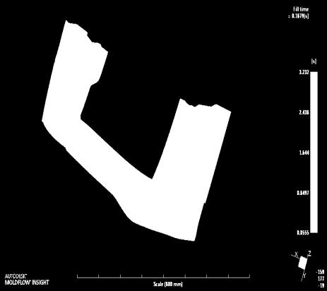
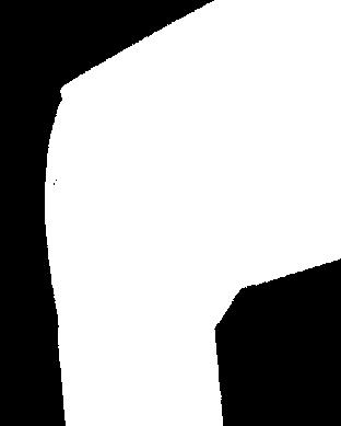
16 IV. Overmolding simulations Overmolding process: Filling: No weldlines allowed Controlled filling on both sides of insert Thermal barrier effect of plastic insert Handling of flow changes Insert positionning system, gate positionning and injection nozzles sequence Maintain insert on one mold side during filling Flow front evolution during filling 16


17 IV. Overmolding simulations Overmolding process: Filling: No weldlines allowed Controlled filling on both sides of insert Thermal barrier effect of plastic insert Handling of flow changes Insert positionning system, gate positionning and injection nozzles sequence Maintain insert on one mold side during filling Flow front evolution during filling Overmolded area: Flow goes faster Non overmolded area 17


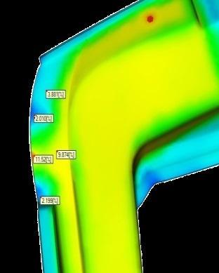
18 IV. Overmolding simulations Overmolding process: Aspect concerns: Overmolded areas Hotter areas Additional packing needed Optimization to limit difference of surface aspect between non overmolded/ overmolded area Surface quality index Initial design and processing conditions After optimization loop 18
19 V. Take away Benefits of the process simulations: Identifications of specific one-shot issues on final part (aspect, cycle time, geometry) Optimized part design Optimized processing conditions Validation of part design for structural requirements as process-compatible Current limitations No coupling of insert forming process and overmolding process (fiber orientation, thickness, insert temperature, ) Insert is considered as an anisotropic solid insert Partial or complete remelting of insert not considered in results (insert displacement, warpage) 19
20 V. Take away 20
21