Computer Assisted Surgery Basics of medical imaging
|
|
|
- John Daniels
- 5 years ago
- Views:
Transcription

1 Computer Assisted Surgery Basics of medical imaging Prof. Leo Joskowicz School of Engineering and Computer Science The Hebrew University of Jerusalem, ISRAEL
2 Medical Image Processing Basics of medical imaging Prof. Leo Joskowicz School of Engineering and Computer Science The Hebrew University of Jerusalem, ISRAEL
3 Recommended literature Chapter 9: Imaging modalities. K. H. Wong, Image-Guided Interventions: Technology and Applications, T. Peters and K. Cleary eds, Springer, 2008, pp


4 First Medical Image: Xrays Roentgen, 1895
5 Characteristics of medical images Intensity values are related to physical tissue characteristics which in turn relate to a physiological phenomenon Physics Anatomy Physiology

6 Imaging devices spectrum


7 Physics of imaging modalities CT MRI Density of X-Ray absorption Density and structure of protons Ultrasound Scintigraphy Variations of Acoustic Impedance Density of injected isotopes
8 Most common imaging modalities X-rays: film, digital, fluoroscopy, Digital Substraction Angiography (DSA) Ultrasound: 2D and 2.5D (stack of slices) Video: laparoscopes and endoscopes CT: Computed Tomography MRI: Magnetic Resonance Imaging NM: Nuclear Medicine PET -- Positron Emission Tomography SPECT -- Single Photon Emission Tomography Many specialized modalities: DSA, heart, etc.
9 Medical images: characteristics (1) Preoperative or intraoperative use depends on the size and location of imaging machine Dimensionality: 2D, 2.5D, 3D, 4D, 5D projection, cross section, stack of projections, time 3D reconstructions, sequences, evolution over time Image quality pixel intensity and spatial resolution amount of noise; signal/noise ratio spatial distortions and intensity bias
10 Medical images: characteristics (2) Field of view Radiation to patient and to surgeon Functional or anatomical imaging neurological activity, blood flow, cardiac activity What it s best for bone, soft tissue, fetus, surface/deep tumors, etc Clinical use diagnosis, surgical, navigation
11
 High frequency ultrasound Fluorescence microscopy Optical coherence")
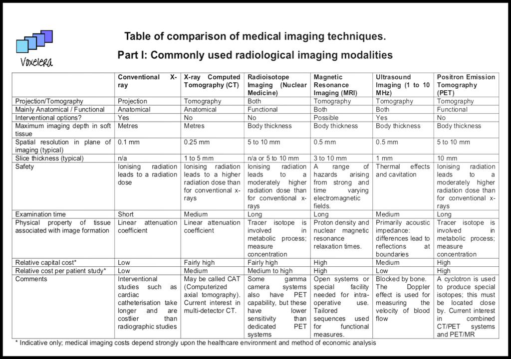
12 Table of comparison of medical imaging techniques. Part II: Less commonly used in vivo imaging modalities. (These have higher spatial resolution than those in Part I, and may be in the early stages of development for in vivo use) High frequency ultrasound Fluorescence microscopy Optical coherence tomography In vivo confocal microscopy Spectrophotometric intracutaneous analysis Diffuse optical tomography Terahertz pulsed imaging High resolution MRI Projection/Tomography Tomography Projection Tomography Tomography Projection Tomography Both Tomography Mainly Anatomical / Anatomical Functional Anatomical Anatomical Both Functional Both Anatomical Functional Maximum imaging depth in 4 mm 0.5 mm 2 to 3 mm 400 µm 2 mm 15 cm Few mm cm soft tissue Spatial resolution in plane 20 µm 1 µm 10 µm 2 to 5 µm Up to 10 µm 1 to 3 mm 350 µm 100 µm of imaging (typical) Depth resolution (typical) 9 µm n/a 5 to 15 µm 0.5 µm n/a 1 to 3 mm 40 µm 100 µm Safety Thermal effects and cavitations Thermal effects Thermal effects Physical property of tissue associated with image formation Comments Primarily acoustic impedance: differences lead to reflections at boundaries MHz. High frequency Doppler under development May involve administration of fluorophores. Decay time of fluorescence induced by laser light, plus spectrum and intensity, give molecular environment e.g. FLIM Fluorescence Lifetime Imaging. Visible light. Consult special guidelines regarding use in eye Refractive index. Interferometric techniques used to infer time of flight OCT. Can be used endoscopically. Visible light. Consult special guidelines regarding use in eye Uses reflected light or fluorescence Accessible tissue surfaces, planes parallel to surface. Visible light. Effect of the skin s chromophores (haemoglobin, melanin, collagen, dermal melanin) SIAscopy analytical version of dermatoscopy or ELM. Visible light & NIR. Refractive index and scattering, chromophore content and absorption Monitor tissue and blood oxygenation levels. Near infrared (NIR). Complex refractive index affecting pulses of radiation. Also spectroscopy. mmwave imaging is a passive technique at similar frequency. Hazards from strong and time varying electromagnetic fields Proton density and nuclear magnetic resonance relaxation times Using special small coils in a 1.5-3T whole body scanner. Note. We might also have included spectroscopic methods such as Fourier Transform Infrared (FTIR) spectroscopy and Raman spectroscopy, which were originally non-imaging laboratory tools. They are now being applied in vivo and with data mapping to generate images. This is the May 2006 download from by Elizabeth Berry Ltd E&OE. This information is provided as an introductory guide. It is for educational or informational use only, and is not to be used for patient care. Part I of the table includes the more commonly used radiological imaging modalities. It was the January 2006 download from


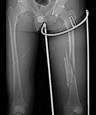
13 X-ray images Film or Digital X-ray X-ray Fluoroscopy

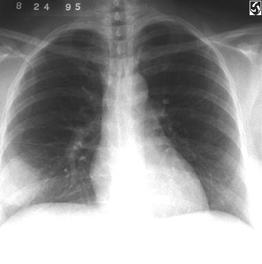
14 X-ray imaging
15

16 Fundamentals of X-ray Physics X-ray is an electromagnetic waveform. The energy: hc E = hν = λ The wavelength and the energy of diagnostic x rays: 0.01nm λ 0.1nm 12.4keV E 124keV

![resolution z I o µ = linear attenuation coefficient [cm -1 ]](/docs-images/87/96482493/images/17-1.jpg "I d Gray value proportional to radiation energy I d = I o")
17 X-ray imaging: principle Measure absorption of X-ray radiation from source to receptors Film X-ray has very high resolution z I o µ = linear attenuation coefficient [cm -1 ] I d Gray value proportional to radiation energy I d = I o exp[ µ dz]

18 Record the x-ray flux impinging on the x-ray detector after attenuation by a patient
19 Beer Lambert Law Attenuation (1) Materials along the ray have different attenuation coefficients:
20 take the logarithm: Attenuation (2) How can we derive the density (or attenuation) distribution µ out of the measured intensities?
21 Record the x-ray flux impinging on the x-ray detector after attenuation by a patient I = I e I = I e Δ 0 0 µ x n= 1 N µ Δx N I p= ln = µ nδx µ x 0 ( x) dx Δ I0 n= 1 L p the projection measurement L the x ray path n
22
23
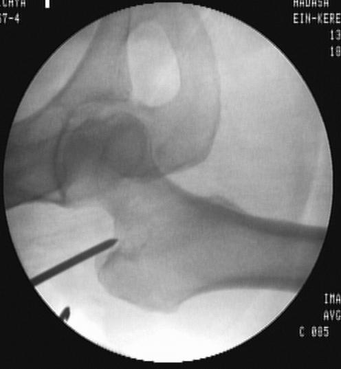
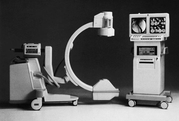
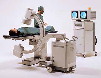
24 X-ray fluoroscopy
25

26 Xray imaging with contrast agent
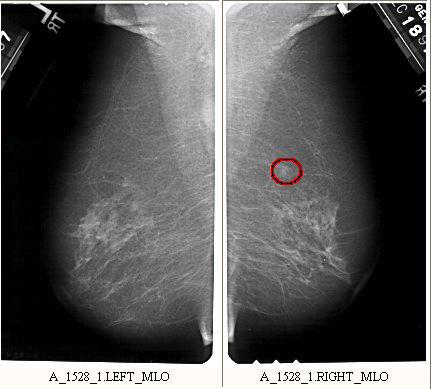
27 Xray mammography

28 Angiography continuous fluoroscopy Use of injected contrast agent
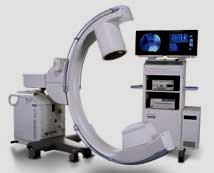
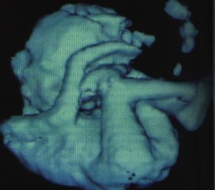
29 3D X-ray fluoroscopy (Iso3D C-arm)
30 X-ray image properties Traditional, cheap, widely available 2D projections (at least two required) High resolution, low noise (more fluoroscope) film size, 64K gray levels fluoroscopic images: TV quality, 20cm field of view Relatively low radiation Bone and metal images very well Fluoroscopy used for intraoperative navigation Also dynamic (angiography), bi-planar.
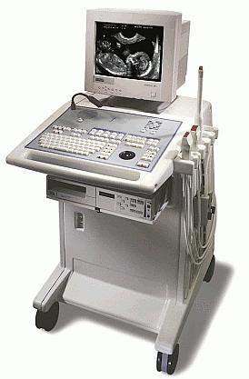
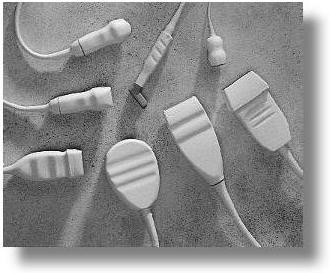
31 Ultrasound imaging


32 Ultrasound: principle Probe sends high-frequency (1 5Mhz) sound waves into body Sound waves travel into tissue and get reflected by boundaries Reflected waves recorded by probe Time of flight gives spatial info of the boundaries Frequency of signal depends on a trade-off resolution versus attenuation
33 Reflection, Diffraction, Refraction of US Waves Reflection of sound waves Reflection of sound waves off surfaces can lead to the phenomenon of an echo. Diffraction of Sound Waves Diffraction involves a change in direction of waves as they pass through an opening or around a barrier in their path. The amount of diffraction (the sharpness of the bending) increases with increasing wavelength and decreases with decreasing wavelength. Refraction of Sound Waves Refraction of waves involves a change in the direction of waves as they pass from one medium to another. Refraction, or bending of the path of the waves, is accompanied by a change in speed and wavelength of the waves. 33

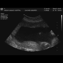
34 Ultrasound imaging: characteristics No radiation Poor resolution (1mm) nonuniform, distortion, noise Low penetration properties One 2D slice or several slices (2.5D) Relatively cheap and easy to use Preoperative and intraoperative use
35 !"#$%&'()*+%,- (.&/01
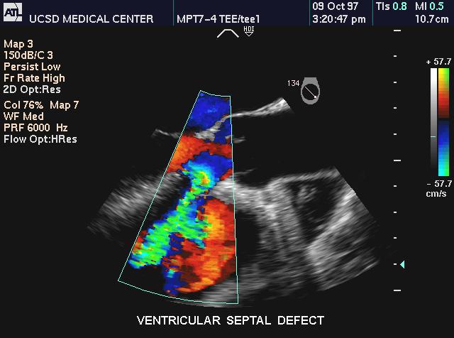
36 !"#$%&'()*+%,- (.&/01
37 !"#$%&'(")*+,(-&.' /01+&., 2 03"$-(%,''14&.,*"4#$"%$*"'*(-,*4&'(* )&44&%56*7',.*4,(-&. 2 8)-&*#495"(7.,'*#3,*$3#61')#5,*,%)&.,.:*;"(-* (-,*-"$-,'(*#495"(7.,'*,%)&.,.*"%*;-"(, 2 <&$#3"(-4")*')#5"%$*"'*,495&6,.*(&*)&"%)".,* ;"(-*(-,*,6,'*#="5"(6*(&*."'),3%*.">>,3"%$*'-#.,'* &>*=3"$-(%,''

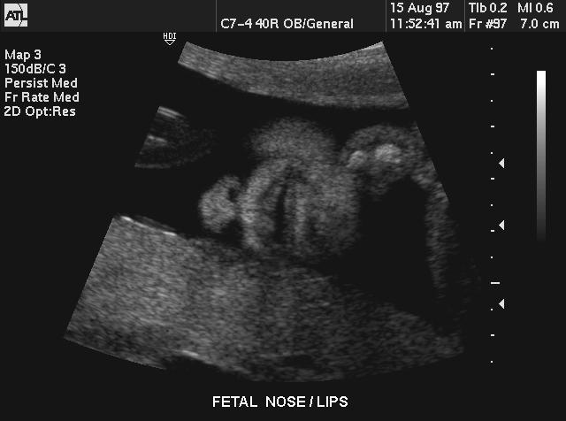
38 Examples of US images -- tumors


39 Reconstruct 3D data from 2D slices 3D ultrasound Acquisition methods: linear, rotation, fanlike, freee-hand
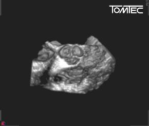
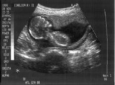
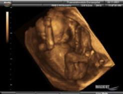
40 3D ultrasound images

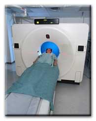
41 Computed Tomography (CT)

42 Development of Computed Tomography

43 CT image quality 1970 s 2001
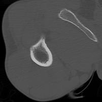
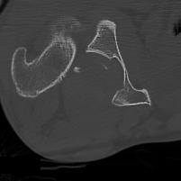
44 Computed Tomography: images cuts d = 5mm d = 15mm d = 25mm d = 35mm
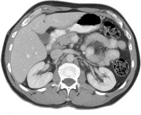
45 Computed Tomography: images Single slice Series of parallel slices 2mm apart


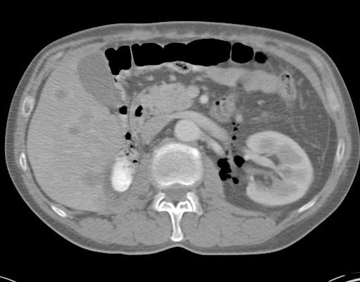
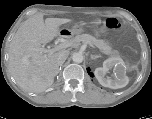
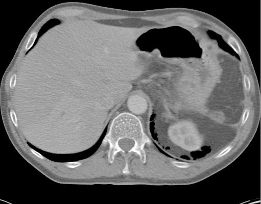
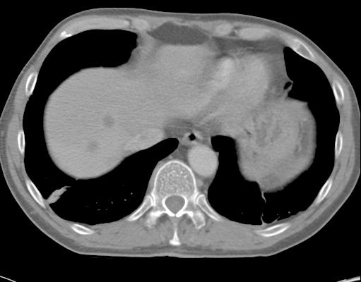
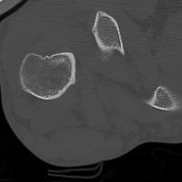
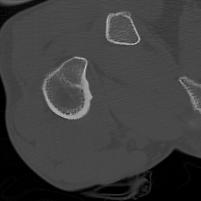
46 CT-scan views Size: 512 x 512 x 128 Resolution: 0.5 x 0.5 x 1 mm 3

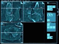
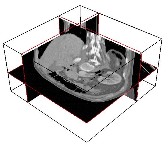
47 Imaging planes


48 Views reconstruction Axial ORIGINAL Sagittal Coronal RECONSTRUCTED
49 Common structure of 3D images Voxel representation M(i,j,k) = I(x,y,z) I(x,y,z) measures the physical properties of a volume element centered around (x,y,z).
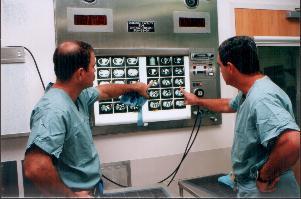
50 Visual examination

51 Computed Tomography: principle X-rays intensity angle
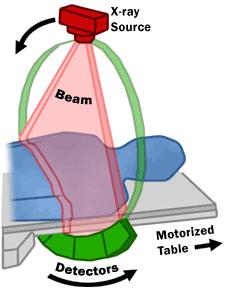

52 What is Tomography? X-Ray Computed Tomography 52
53 Radial intensities graph
54 Computed Tomography: types Planar, parallel or fan (cone)-beam Spiral (helical) Single slice or multi-slice Takes about 1sec/acquisition Current spiral units can take 4 32 and even 64 slices simultaneously! Reconstruction using variations of Fast Fourier Transforms (FFT). Mostly preoperative, some intraoperative units
55 Computed Tomography: properties Specifications: 512x512 12bit gray level images; pixel size 0.5mm slice interval 0.5-5mm depending on anatomy 50-1,000 slices per study noise in the presence of metal (blooming) Grey levels: Hounsfield Units (HU). Air is -1000HU, Water is 0HU, Fat is 100 to 300HU, Water Muscle 10-70HU, Bone > 200HU All digital, printed on X-ray film Costs about $400-1,000, each study $500

56 Cine CT of the heart

57 Ionizing radiation
58 Magnetic Resonance Imaging Similar principle and construction of CT machine, but works on magnetic properties of matter Magnetic fields of 0.3 to 7 Teslas (typical 1.5, 3) Similar image quality characteristics as CT Excellent resolution for soft tissue Costs $1 3M, each study $1,000. Open MR: intraoperative device Odin s portable intraoperative MR (0.3 Teslas) Functional MRI: Diffusion Tensor Imaging (DTI)

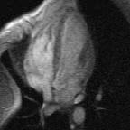
59 Magnetic Resonance Images

60 Types of MRI Protocols Gradient Echo T 1 W T 2 W T 1 W-post Gd FLAIR 3D-fspgr-post Gd
61 MRI principle 1. Put anatomy in large magnetic field 2. Transmit radio waves into anatomy [2~10 ms] 3. Turn off radio wave transmitter 4. Receive radio waves re-transmitted by subject 5. Convert measured radio frequency data to image Important factors Quantum properties of nuclear spins Radio frequency (RF) excitation properties Tissue relaxation properties Magnetic field strength and gradients Timing of gradients and RF pulse
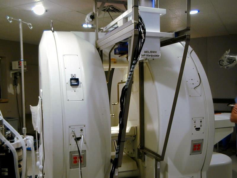
62 Open MR

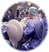
63 Odin MR system
64

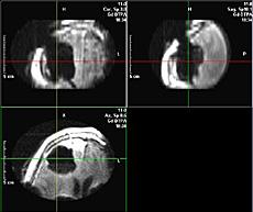
65 Odin MR images
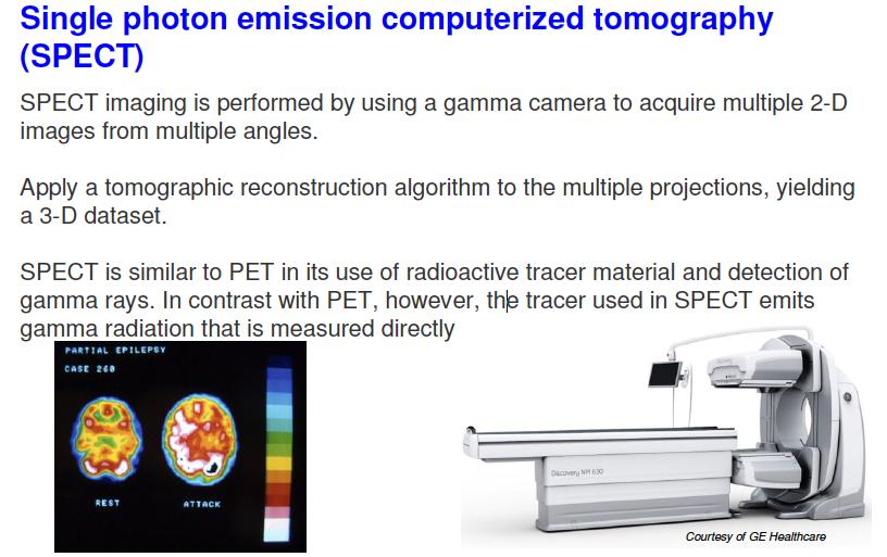
66 Nuclear Medicine Imaging (NMI) Same slices principle Source of photons or positrons is injected in the body. Shortly after, radiation of metabolism is measured. PET (1953), SPECT (1967) Poor spatial resolution Expensive machine AND installation ($4-5M) Expensive scan and time-consuming Provides functional info no other source does
*(+,-.")
67 !"# $%&'()*(+,-.&(/012)+*1

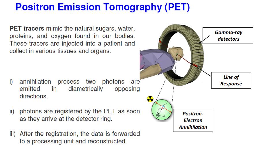
68 PET: Positron Emission Tomography
69 PET: Positron Emission Tomography
70

71 PET images


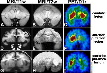
72 Tracers show functional information such as glucose metabolism, and perfusion Useful to: Find tumors Show strokes Heart assessment Functional neuroscience PET uses PET scan on the brain showing Parkinson s disease

73 PET/CT
74
75 !"#$%&'()'*&+*),-+&./&01-&23')4
76 !"#$%&'()*+,&-.&/0+&0+)1/

77 Brain fmri images


78 Image Fusion: MRI and NMI MRI (anatomy) NMI (functional)
79 Multimodal imaging


80 Video images from within the body Used in laparoscopic and endoscopic surgery
81 Laparoscopy
82 Medical imaging: summary Many types of images, both anatomical and functional Trend towards stacks of parallel slices Experts: Radiologists Need: software to visualize and process them!
83 The future of medical imaging
84 References Principles of Medical Imaging Shung et al, Academic Press, NY, 1992 Foundations of Medical Imaging Cho et al, Wiley, NY, 1993 Medical Imaging Systems, Macovski, Prentice Hall, NJ, 1983