MECHANICAL AND ADHESIVE PROPERTIES OF ARAMID/NYLON INSERT INJECTION MOLDING COMPOSITES
|
|
|
- Vivien Harrell
- 5 years ago
- Views:
Transcription
1 MECHANICAL AND ADHESIVE PROPERTIES OF ARAMID/NYLON INSERT INJECTION MOLDING COMPOSITES Badin Pinpathomrat, Hiroyuki Hamada Kyoto Institute of Technology, Kyoto, Japan Abstract A new joining method called "insert-injection molding" is a novel technique for combining polymer products to enhance mechanical properties and durability. Hence, insert-injection molding is introduced for adhering automotive parts without using bolts or adhesives. The thermoplastic system inserted in this study is aramid/polyamide 6 (aramid/pa6). The injected part is glass fiber reinforced polyamide 6 resin (GF/PA6). The aramid/pa6 was inserted in the mold cavity before being injected with GF/PA6 resin to make insert injection molded specimens. The interfacial bonding strength between the inserted and injected polymer parts was measured by performing bending tests (with the aramid/pa6 on the tension side) in order to investigate the effect of the inserted materials and injection molding conditions on the mechanical properties. In addition, the effect of the inserted orientation on the mechanical properties of the aramid/pa6 insert-injection molding system was investigated. The Morphology of the fracture surfaces of aramid/pa6 insert-injection molded composite specimens was observed by optical microscopy. The aramid/pa6 insert-injection molded composites have significantly higher flexural strength than the non-inserted injection moldings made from GF/PA6. In addition, the injection molding conditions were varied to improve the bonding properties of the aramid/pa6 insert-injection moldings. Microscopy observations indicate that structural failure was primarily caused by thru-thickness cracking originating from the aramid/pa6 region. Introduction Fiber-reinforced polymer composites (FRP) are applied in various applications such as automobiles, aerospace, and construction due to their advantages of high specific strength with excellent mechanical performance and structural efficiency [1]. FRP composites are generally adhered with different parts of an infrastructure [2-3]. Automotive parts are mostly joined with bolts or adhesives. The Insert-injection molding process is an advanced injection molding technology that uses dissimilar materials to produce complex parts [4]. This unique manufacturing process combines metal and plastic, ceramics, or multiple combinations of materials and components into a single unit. This process is used to mold specimens by injecting melted polymer onto the inserted part that is placed in the injection molding cavity [5-6]. Hence, Insert-injection molding has been introduced for combining automotive parts without using bolts or adhesives. On the other hand, insert-injection molding, also known as two stages sequential insert molding, is an injection molding process using a rigid substrate or the flexible material. The insert can either be incorporated at the time of the molding process or can be inserted post molding operation. However, there is less information on the insert- injection molding process. In this study, we introduced aramid/nylon composites as an insert in this molding process. Glass fiber-reinforced Polyamide 6 (GF/PA6) resin is injected onto the inserted aramid/nylon. The role of adhesion between the inserted part and injected resin on the mechanical properties and fracture morphology was measured by bending testing and optical microscopy, respectively. The effects of the inserted aramid/nylon orientation on the mechanical properties of the molding system were investigated.
 (Grade A13BRL) was provided by Unitika Limited, Japan.")

2 Materials and Sample Preparation Experimental The Aramid/nylon composite was cut to dimensions of 15 mm long x 1 mm wide x.3 mm thick as an inserted part. This part was placed into the mold cavity before being injected with polymer resin. The 3 wt% glass fiber reinforced polyamide 6 (GF/PA6) (Grade A13BRL) was provided by Unitika Limited, Japan. GF/PA6 was injected into the mold cavity with dimensions of 15 x 1 x 3.5 mm, according to ASTM standard D638 (TOYO MACHINERY & METAL CO., Ltd, TI-3F6, Japan). Table 1 summarizes the processing conditions for the insert-injection molded specimens. Table 2 tabulates the specimen codes of the insert-injection molding conditions. Figure 1 shows photographs of the insert-injection moldings made under various processing conditions. Table 1: Materials and the injection molding parameters. Condition Values Insert part Aramid/Nylon Injection part Polyamide 6 Mold temperature 6 C 9 C C Barrel temperature 26 C 27 C Holding pressure 2 MPa Cooling time 15 s No Table 2: Specimen designation. Code Mold Temperature ( C) Barrel Temperature ( C) PA Figure 1: Photographs of the insert-injection molding specimens.
3 Characterization Three-point bending tests were performed according to ASTM D79 using an Instron universal testing machine (Instron model 426, USA). The specimens were cut to the dimensions of 6 mm (length) x 1 mm (width) x 3 mm (thickness). The span length was set at 48 mm, and the testing speed was 3 mm/min. Morphology of the fractured surfaces of the insert injection molded specimens was observed by optical microscopy and scanning electron microscopy (SEM) (JSM 52, JEOL, Japan). Results and discussion Mechanical properties of insert-injection moldings Figure 3 shows typical load displacement curves from bending tests of the aramid/pa6 insert-injection molding composite specimens. The maximum load of the insert-injection specimens was higher than that of GF/PA6. The effect of the barrel and mold temperatures on the aramid/pa6 and GF/PA6 bonding is presented in Figure 3 (a) and (b). It should be noted that the maximum load obtained was about 35-4 N with an elongation between 1 and 2 mm at a mold temperature of 6 C, as shown in Figure 3 (a). At 9 C, the maximum load obtained was approximately 4-45 N with an elongation between 15 and 25 mm as shown in Figure 3 (b) a GFPA Normal 5 45 b GFPA Normal 4 6/ 4 9- Load (N) / Load (N) Displacement (mm) Displacement (mm) Figure 3: Load-displacement curves of insert injection moldings. (a) mold temperature of 6 C, (b) mold temperature of 9 C. The flexural strength is presented in Figure 4. The flexural strength of the aramid/pa6 insert-injection molding composite specimens was higher than that of neat GF/PA specimens. When inserting aramid/pa6 to make the insert-injected moldings, the flexural strength was greatly improved. It was observed that the inserted aramid/pa6 composite moldings were better able to resist damage under bending loading. This inserted technique can increase the failure resistance in bending, which processed on buckling and kinking of the aramid/pa6 composites inserted [7]. The interfacial adhesive strength of all aramid/pa6 insert-injection molded composite specimens increased with increasing barrel and mold temperatures. The significant improvement in the aramid/pa6 and GF/PA6 bond with increasing barrel temperature was due to higher molecular interdiffusion of the melted PA6 resin at the aramid/pa6 interface. The fracture mode of the insert-injection molded specimens was dependent on the barrel and mold temperatures of the injection molding conditions. The maximum flexural strength of the insert-injection moldings was found in sample 9-27 where high barrel temperatures with high mold temperatures were used.
4 Flexural strength (MPa) GFPA Normal a Flexural strength (MPa) GFPA Normal b Figure 4: (a) Flexural strength of the insert injection moldings. (a) mold temperature 6 C, (b) mold temperature 9 C. Figure 5 presents the initial fracture strain in aramid/pa6 insert-injection molding composite specimens [8]. A knee-point can be observed. All of the insert-injection molding specimens required a higher strain than the GF-reinforced polymer molding specimen until initial cracking occurred, as shown in Figure 5. This can be attributed to partial adhesion in the insert-injection molding specimens. 7 Initial fracture strain (%) GFPA Normal Figure 5: Initial fracture stress of the insert-injection moldings. Morphology and fracture behavior of inserted injection molded Figure 6 shows optical photographs of the aramid/pa6 insert-injection composite molding specimens after bending tests. From the results, Figure 6 (a) shows photographs of the aramid/pa6 insert-injection molding composite specimens before bending tests. It was found that in both 6- and 6-26, interfacial failure resulted in the separation of the substrate from the adhesive layer, as show in Figure 6 (b) and (c). On the other hand, in Figure 6 (d), (e), (f) and (i) structural failure as well as adhesive failure between the injected part and the inserted part is present. It can be seen that the fracture of the specimens occurred in the region where the aramid was inserted into the PA6, initiating from the bottom of the images as shown in figure 6. In addition, the specimens with a low barrel temperature and low mold temperature had poorer adhesion and were easily broken during bending testing, as presented in Figure 6.

 6-26")
 9-")
 9-27")

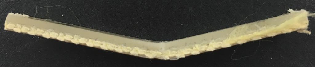
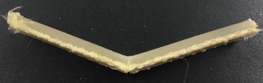

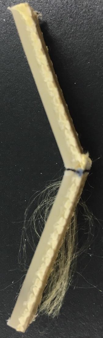


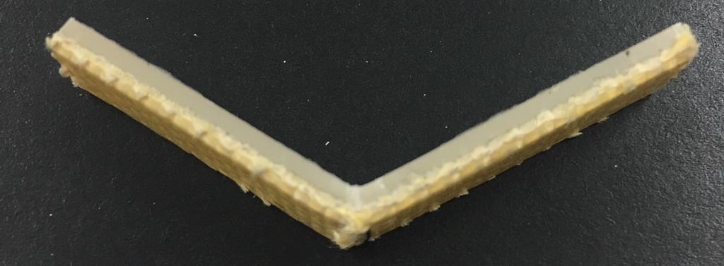

5 (a) Normal (b) 6- (c) 6-26 (d) 6-27 (e) 9- (f) 9-26 (i) 9-27 Figure 6: Optical photographs of aramid/pa6 insert-injection molding composite specimens after bending tests.
6 Conclusions The adhesive properties of the interface in the aramid/pa6 insert-injection moldings was presented. The adhesive properties of aramid/pa6 insert-injection moldings were significantly affected by the barrel and mold temperatures. The significant improvement in the aramid/pa6 and GF/PA6 bond with increasing barrel temperature was due to higher molecular interdiffusion of the melted PA6 resin at the aramid/pa6 interface. The flexural strength of the aramid/pa6 insert-injection molding is superior to that of an injection molding with no added insert. During bending testing of the specimens, structural failure was marked by cracking that occurred in both the Aramid/PA6-inserted part and the polymer-injected part. However, the insert-injection molded composites were able to sustain higher stresses than the non-inserted injection molding specimens prior to initial cracking. The insert-injection molding process can provide many benefits for fabricating joint materials and reinforced composites. Bibliography 1. Yoshio N., Robert D., Handbook of Semiconductor Manufacturing Technology. New York: Marcel Dekker; Ryosuke M, Motoko S., Akira T., Composites Part A, Vol. 39, pp. 154, Mohan N.S., Kulkarni S.M., Ramach A., Composites Science and Technololy, Vol. 186, pp. 265, Davim J.P., Reis P., Antonio C.C., Composites Science and Technololy, Vol. 64, pp. 289, O'Higgins R.M., McCarthy M.A., McCarthy C.T., Composites Materials, Vol. 4, pp. 269, Bohse J., Journal of Acoustic Emission, Vol. 22, pp. 28, Budiansky B., Fleck N.A., Mechanics USA 1994, Applied Mechanics Reviews, Vol. 47, No. 2, part 2, pp. S246-S, Nakai A., Osada T., Hamada H., Takeda N., Composites Part A, Vol. 32, pp , 21.