Set up the Grid: From the drop down menu: Settings, Configuration, Screen, Grid Settings
|
|
|
- Bertram Hamilton
- 5 years ago
- Views:
Transcription
 PivotClamp.")
1 ENGI 7928 Mastercam Lab Mill 1 C. Koenig 2012 Starting a Mastercam file: Once the SolidWorks models is complete, save the model as PivotClamp.x_t, Open Mastercam, select: File, Open, Files of type All Files (*.*) PivotClamp.x_t Set up the Grid: From the drop down menu: Settings, Configuration, Screen, Grid Settings ENGI 7928 Computer Aided Engineering, Memorial University C. Koenig 1
 Move, -1.")
2 Orient the part, set the Origin at the upper left corner in X&Y and top face in Z. Xform, Translate, Draw a box around the entire part, select Green button (End Selection) Move, -1.0 in Y direction, OK ENGI 7928 Computer Aided Engineering, Memorial University C. Koenig 2
3 To move part in Z direction Select Front View Xform, Translate, draw a box around the entire part, select End Selection Move, in Z direction, OK ENGI 7928 Computer Aided Engineering, Memorial University C. Koenig 3

4 Alt -S will shade the part, we will work in Wireframe mode Select Machine Type: Mill, Default Setting up Machine Group Properties: Expand Properties in the Operations Manager & set up fields as shown ENGI 7928 Computer Aided Engineering, Memorial University C. Koenig 4

5 Files: as shown ENGI 7928 Computer Aided Engineering, Memorial University C. Koenig 5

6 Tool Settings: edit fields as shown below, pick Select ENGI 7928 Computer Aided Engineering, Memorial University C. Koenig 6


7 Under Source, pick: Mill Library, change material to Aluminum 6061 ENGI 7928 Computer Aided Engineering, Memorial University C. Koenig 7


8 Setup stock as shown, use the mouse & pick the upper left hand corner of the stock envelop to set up the Stock Origin, OK Select Isometric & Fit ENGI 7928 Computer Aided Engineering, Memorial University C. Koenig 8

9 Machining operations: Before machining the part, operation order must be determined and clamping method selected. For this component we will machine all operations in a vice leaving the outside profile last, which will be machined in a dedicated fixture. Machining Operations are as follows: Machining Operation 1 Facing 2 Contour 3 Circle Mill 4 5 Simple drill - no peck Peck drill - full retract 6 Circle Mill 7 Pocket 8 Pocket 9 Contour Tool Type Face Mill End Mill End Mill Spot Drill Drill End Mill End Mill End Mill End Mill Tool Description 2" Face Mill 3/4 FLAT ENDMILL 1/4 FLAT ENDMILL 1/2 SPOTDRILL NO. 36 DRILL 3/4 FLAT ENDMILL 1/4 FLAT ENDMILL 1/4 FLAT ENDMILL 1/2 FLAT ENDMILL Operation Comment FACE TOP OF STOCK MILL TOP FACE FOR BOSS CIRCLE MILL.750 DIA. HOLE SPOT DRILL X12 TOP OF BOSS PECK DRILL X12 THRU CIRCLE MILL.90 DIA. HOLE POCKET TRAINGLE FEATURE POCKET SLOT PROFILE OUTSIDE EDGE ENGI 7928 Computer Aided Engineering, Memorial University C. Koenig 9

10 Operation 1: Facing- Face Top of Stock Tool Number: 1 Tool Type: Carbide, 2 Ø, 6 Tooth, Face Mill ENGI 7928 Computer Aided Engineering, Memorial University C. Koenig 10
11 Select the largest upper circular profile (1.5 dia.), OK 2D Toolpaths- Facing, Tool Path Type ENGI 7928 Computer Aided Engineering, Memorial University C. Koenig 11


12 Select Library tool, Filter, None, select the Face Mill icon, select 2 Face Mill tool, OK, OK Define Tool: Double click the tool #316 change to #1 on the Define Tool page ENGI 7928 Computer Aided Engineering, Memorial University C. Koenig 12

13 2D Toolpaths-Facing, Tool: Edit all fields as shown below and add comment. 2D Toolpaths- Facing, Cut Parameters: Edit all fields as shown below, select One pass, ENGI 7928 Computer Aided Engineering, Memorial University C. Koenig 13
14 2D Toolpaths- Facing, Linking Parameters: Edit all fields as shown below. 2D Toolpaths- Facing, Coolant: coolant On, OK ENGI 7928 Computer Aided Engineering, Memorial University C. Koenig 14

15 Select Verify Selected Operations Select Machine ENGI 7928 Computer Aided Engineering, Memorial University C. Koenig 15


16 Top of stock has been faced.025 Use Verify to check the part is being machined using the correct tool, toolpath direction, to appropriate depth cuts, rough cuts, & finish cuts. Select all operations, Verify, Select the Simulate Tool & adjust settings for Quality & Speed etc. Try using Backplot which displays toolpath, rapid moves, moves from feed plane and depth moves. Select all operations, Backplot, expand dialogue box, select Info for Cycle Times ENGI 7928 Computer Aided Engineering, Memorial University C. Koenig 16


17 Cutter rotation and cutter travel direction: When conventional machining on manual milling machines we generally feed the part against the direction of the cutter, referred to as conventional milling. When CNC machining we are generally working with a more rigid machine. If the part is rigidly held in by vice/fixture we will feed the part in the direction of the cutter know as climb milling. When working in Mastercam the tool looks like it is moving, even though in reality we know the CNC machine table is moving. Therefore, to ensure we are climb milling, remember the tool in Mastercam will move in a clockwise direction on an outside profile and counterclockwise direction on an inside profile (Clockwise outside- Counterclockwise inside). Precision Machining Technology, Hoffman, Hopewell, Janes & Sharp, Copyright 2012 ENGI 7928 Computer Aided Engineering, Memorial University C. Koenig 17
, toolpath direction (green arrow) should be pointed in a CW direction ENGI 7928 Computer Aided Engineering, Memorial University C.")
18 Operation 2: Contour - Mill Top Face for Boss Tool Number: 2 Tool Type: HSS ¾ Centre Cutting Flat End Mill, 2 Tooth Toolpaths, Contour, Select the top circle (1.5 diameter), toolpath direction (green arrow) should be pointed in a CW direction ENGI 7928 Computer Aided Engineering, Memorial University C. Koenig 18


19 When selecting an entity make sure Chain is activated. The toolpath direction can be changed by selecting Reverse. When Climb Milling remember the toolpath direction is Clockwise outside Counterclockwise inside. Select the Reverse command to change the toolpath Direction. 2D Tooplaths Contour, Toolpath Type: Edit all fields as shown below. ENGI 7928 Computer Aided Engineering, Memorial University C. Koenig 19
20 2D Tooplaths- Contour, choose Select Library Tool & Filter below. Select None, select the EndMill1 Flat icon, OK ENGI 7928 Computer Aided Engineering, Memorial University C. Koenig 20


21 Select 3/4 FLAT ENDMILL, OK Define Tool, double click the tool #241, change the tool number to 2, OK. ENGI 7928 Computer Aided Engineering, Memorial University C. Koenig 21

22 2D Toolpaths- Contour, Tool: Edit all fields as shown below. 2D Toolpaths- Contour, Cut Parameters: Edit all fields as shown below. ENGI 7928 Computer Aided Engineering, Memorial University C. Koenig 22
23 2D Toolpaths- Contour, Depth Cuts: Edit all fields as shown below. 2D Toolpaths- Contour, Multi Passes: Edit all fields as shown below. ENGI 7928 Computer Aided Engineering, Memorial University C. Koenig 23
24 2D Toolpaths- Contour, Linking Parameters: Edit all fields as shown below. 2D Toolpaths- Contour, Coolant: Edit all fields as shown below. ENGI 7928 Computer Aided Engineering, Memorial University C. Koenig 24
 pick Geometry, Right Click Chain 1, select Start Point ENGI 7928 Computer Aided Engineering, Memorial University C.")
25 Select all operations, Backplot, note that the ¾ Endmill tool plunges into the stock- we will move the start point to reduce wear on the cutter. Under operation 2-Contour (2D) pick Geometry, Right Click Chain 1, select Start Point ENGI 7928 Computer Aided Engineering, Memorial University C. Koenig 25


26 Pick Move Dynamic, position the new start point as shown below, OK.. Regenerate Dirty Operations will clean up the toolpaths, Backplot to check machining operation ENGI 7928 Computer Aided Engineering, Memorial University C. Koenig 26

27 Operation 3: Circle Mill Circle Mill.750 Diameter hole Tool Number: 5 Tool Type: HSS 1/4 Centre Cutting Flat End Mill, 4 Tooth Select the.750 top circle shown below, OK. ENGI 7928 Computer Aided Engineering, Memorial University C. Koenig 27

28 Tool, Select Library tool, Filter, None, select EndMill1 Flat icon, OK, select ¼ FLAT ENDMILL, OK, Double click the tool number and change to tool 5 on the define tool page, OK. 2D Toolpaths- Circle Mill, Tool: Edit all fields as shown below. 2D Toolpaths- Circle Mill- Cut Parameters: Edit all fields as shown below. ENGI 7928 Computer Aided Engineering, Memorial University C. Koenig 28
29 2D Toolpaths- Circle Mill- Depth Cuts: Edit all fields as shown below. 2DToolpaths- Circle Mill- Break through: Edit all fields as shown below. ENGI 7928 Computer Aided Engineering, Memorial University C. Koenig 29

30 2D Toolpaths- Circle Mill- Multi Passes: Edit all fields as shown below. 2D Toolpaths- Circle Mill- Linking Parameters: Edit all fields as shown below. ENGI 7928 Computer Aided Engineering, Memorial University C. Koenig 30
31 2D Toolpaths- Circle Mill- Coolant: Edit all fields as shown below. Operation 4: Spot Drill Spot Drill x 12 top of Boss Tool Number: 3 Tool Type: Carbide Insert, 1/2 Spot drill ENGI 7928 Computer Aided Engineering, Memorial University C. Koenig 31

32 Select the centre of the 12,.106 Dia. holes as shown, OK. Tool, Select Library tool, Filter, None, select Spot Drill, scroll down & pick the ½ SPOTDRILL, OK, Double click the tool number and change to tool 3 on the define tool page, OK. ENGI 7928 Computer Aided Engineering, Memorial University C. Koenig 32

33 2D Toolpaths- Drill/CirclesSimple drill, Tool: Edit all fields as shown below. 2D Toolpaths- Drill/CirclesSimple drill, Cut Parameters: Edit all fields as shown below. ENGI 7928 Computer Aided Engineering, Memorial University C. Koenig 33

34 2D Toolpaths- Drill/CirclesSimple drill, Linking Parameters: Edit all fields as shown below. 2D Toolpaths- Drill/CirclesSimple drill, Coolant: Edit all fields as shown below. ENGI 7928 Computer Aided Engineering, Memorial University C. Koenig 34


35 Select all operations, Verify, Play ENGI 7928 Computer Aided Engineering, Memorial University C. Koenig 35


36 Copying a previous operation: Select only the Drill/Counterbore Folder, Right Click this folder and drag it BELOW the Red Insert Arrow & then let it go. Select Copy after, we now have a copy of the previous Drill/Counterbore folder we used to spot drill the top of the part. We will now edit the parameters to drill the holes thru. Move the cursor next to the Red Insert Arrow key, pick the Down Red Insert Arrow to move insert arrow down one item. Now pick operation 5-Drill/Counterbore Parameters folder to edit parameters for the drilling operation. ENGI 7928 Computer Aided Engineering, Memorial University C. Koenig 36
37 2D Toolpaths- Drill/CirclesSimple drill, Tool: Edit all fields as shown below. Tool, Select Library tool, Filter, None, select Drill, OK, scroll down & pick NO. 36 DRILL, OK, Double click the tool number and change to tool 4 on the define tool page, OK. 2D Toolpaths- Drill/CirclesSimple drill, Cut Parameters: Edit all fields as shown below ENGI 7928 Computer Aided Engineering, Memorial University C. Koenig 37

38 2D Toolpaths- Drill/CirclesSimple drill, Linking Parameters: Edit all fields as shown below 2D Toolpaths- Drill/CirclesSimple drill, Tip Comp: Edit all fields as shown below ENGI 7928 Computer Aided Engineering, Memorial University C. Koenig 38
39 2D Toolpaths- Drill/CirclesSimple drill, Coolant: Edit all fields as shown below Operation 6: Circle Mill Circle Mill.750 Diameter hole Tool Number: 2 Tool Type: HSS 3/4 Centre Cutting Flat End Mill, 2 Tooth ENGI 7928 Computer Aided Engineering, Memorial University C. Koenig 39
40 Select the.900 top circle shown below, OK. ENGI 7928 Computer Aided Engineering, Memorial University C. Koenig 40
41 2D Toolpaths- Circle Mill: Select Tool 2D Toolpaths- Circle Mill, Tool: Select the 3/4 FLAT ENDMILL, edit all fields as shown below. ENGI 7928 Computer Aided Engineering, Memorial University C. Koenig 41
42 2D Toolpaths- Circle Mill, Cut Parameters 2D Toolpaths- Circle Mill, Depth Cuts ENGI 7928 Computer Aided Engineering, Memorial University C. Koenig 42
43 2D Toolpaths- Circle Mill, Break Through 2D Toolpaths- Circle Mill, Linking Parameters ENGI 7928 Computer Aided Engineering, Memorial University C. Koenig 43
44 2D Toolpaths- Circle Mill, Coolant Operation 7: Pocket Pocket Triangle Feature Tool Number: 5 Tool Type: HSS 1/4 Centre Cutting Flat End Mill, 2 Tooth Select Toolpaths, Pocket ENGI 7928 Computer Aided Engineering, Memorial University C. Koenig 44
45 Select the top edge of pocket, shown below & ensure the toolpath directions is Counter Clockwise, use the Reverse Direction toll to change it if required, OK. Select each entity that makes up the top pocket shape to close the toolpath. ENGI 7928 Computer Aided Engineering, Memorial University C. Koenig 45
46 2D Toolpaths- Pocket 2D Toolpaths- Pocket, Tool: Edit all fields as shown below. ENGI 7928 Computer Aided Engineering, Memorial University C. Koenig 46


47 2D Toolpaths- Pocket, Cut Parameters: Edit all fields as shown below. 2D Toolpaths- Pocket, Roughing: Edit all fields as shown below. ENGI 7928 Computer Aided Engineering, Memorial University C. Koenig 47

48 2D Toolpaths- Pocket, Entry: Edit all fields as shown below. 2D Toolpaths- Pocket, Finishing: Edit all fields as shown below. ENGI 7928 Computer Aided Engineering, Memorial University C. Koenig 48

49 2D Toolpaths- Pocket, Lead In/Out: Edit all fields as shown below. 2D Toolpaths- Pocket, Depth Cuts: Edit all fields as shown below. ENGI 7928 Computer Aided Engineering, Memorial University C. Koenig 49

50 2D Toolpaths- Pocket, Linking Parameters: Edit all fields as shown below. 2D Toolpaths- Pocket, Linking Coolant: Edit all fields as shown below. ENGI 7928 Computer Aided Engineering, Memorial University C. Koenig 50
51 Operation 8: Pocket Pocket Slot Tool Number: 5 Tool Type: HSS 1/4 Centre Cutting Flat End Mill, 4 Tooth Select Toolpaths, Pocket, select upper slot entities to close the toolpath, CCW direction. 2D Toolpaths- Pocket ENGI 7928 Computer Aided Engineering, Memorial University C. Koenig 51
52 2D Toolpaths- Pocket, Tool 2D Toolpaths- Pocket, Cut Parameters ENGI 7928 Computer Aided Engineering, Memorial University C. Koenig 52
53 2D Toolpaths- Pocket, Roughing 2D Toolpaths- Pocket, Entry Motion ENGI 7928 Computer Aided Engineering, Memorial University C. Koenig 53


54 2D Toolpaths- Pocket, Finishing 2D Toolpaths- Pocket, Depth Cuts ENGI 7928 Computer Aided Engineering, Memorial University C. Koenig 54

55 2D Toolpaths- Pocket, Break Through 2D Toolpaths- Pocket, Linking Parameters ENGI 7928 Computer Aided Engineering, Memorial University C. Koenig 55
56 2D Toolpaths- Pocket, Coolant Operation 9: Contour Machine Outside Profile Tool Number: 9 Tool Type: Carbide 1/2 Centre Cutting Flat End Mill, 4 Tooth Select Toolpaths, Contour, select first contour entity as shown below, CW direction ENGI 7928 Computer Aided Engineering, Memorial University C. Koenig 56
57 Continue to select all outer contour entities.. Carefully select all contour entities until the outside profile is closed. ENGI 7928 Computer Aided Engineering, Memorial University C. Koenig 57

58 Last entity selected, select OK. 2D Toolpaths- Contour, Tool Tool, Select Library tool, Filter, None, select Endmill1 Flat, OK, pick 1/2 FLAT ENDMILL, OK, Double click the tool number and change to tool 9 on the define tool page, OK. Edit all fields as shown below. ENGI 7928 Computer Aided Engineering, Memorial University C. Koenig 58
59 2D Toolpaths- Contour, Cut Parameters: Edit all fields as shown below. 2D Toolpaths- Contour, Depth Cuts: Edit all fields as shown below. ENGI 7928 Computer Aided Engineering, Memorial University C. Koenig 59

60 2D Toolpaths- Contour, Lead In/Out: Edit all fields as shown below. 2D Toolpaths- Contour, Lead In/Out: Edit all fields as shown below. ENGI 7928 Computer Aided Engineering, Memorial University C. Koenig 60
61 2D Toolpaths- Contour, Mulitpasses: Edit all fields as shown below. 2D Toolpaths- Contour, Linking Parameters: Edit all fields as shown below. ENGI 7928 Computer Aided Engineering, Memorial University C. Koenig 61
62 2D Toolpaths- Contour, Coolant: Edit all fields as shown below. Select the final contour operation, Backplot Selected Operations ENGI 7928 Computer Aided Engineering, Memorial University C. Koenig 62

63 Select all operations, Verify Select all operations, Backplot Selected operations, Info, check the Cycle time ENGI 7928 Computer Aided Engineering, Memorial University C. Koenig 63

64 Create a Toolist: Settings, Configuration, Toolpaths, Setup Sheet program, set to GUI (Graphical User Interface), OK. Select all operations, mover cursor over the white area shown below in the Operations Manager & right click, pick Display Options ENGI 7928 Computer Aided Engineering, Memorial University C. Koenig 64


65 Click on the Tool list sheet shown below. Edit the title texts: ENGI 7928 Computer Aided Engineering, Memorial University C. Koenig 65
66 Note the details provided on the Tool List, print the list to include in the report. ENGI 7928 Computer Aided Engineering, Memorial University C. Koenig 66

67 Select Clear Colours & Alt-T to turn off toolpaths Create a Set-Up Sheet, Right Click the grey area next to the tool bars, select X+ ENGI 7928 Computer Aided Engineering, Memorial University C. Koenig 67


68 Select all operations & pick, Create Setup Sheet Select all operations & pick, Create Setup Sheet, form Tool parameters, Available parameter add all options listed in Selected parameter ENGI 7928 Computer Aided Engineering, Memorial University C. Koenig 68


69 Note the details on this Setup sheet, save and print this sheet for the report. Select all operations & post the code ENGI 7928 Computer Aided Engineering, Memorial University C. Koenig 69
 G17 (DEFAULT SETTING, CIRC. MOTION) G40 (DEFAULT SETTING, CUTTER COMPENSTION CANCEL) G49 (DEFAULT SETTING, TOOL LENGTH COMP.")
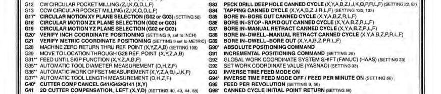
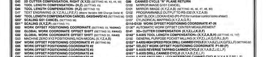
70 Pivot Clamp nc file: Use the G & M Code sheets on the following pages to add annotations to the NC code page, identifying the major operations in plain English. Example: N102 G0 G17 G40 G49 G80 G90 G0 (DEFAULT SETTING, RAPID) G17 (DEFAULT SETTING, CIRC. MOTION) G40 (DEFAULT SETTING, CUTTER COMPENSTION CANCEL) G49 (DEFAULT SETTING, TOOL LENGTH COMP. CANCEL) G80 (DEFAULT SETTING, CANCEL CANNED CYCLE) G90 (DEFAULT SETTING, ABSOLUTE POSITIONING) Congratulations! You have finished the Mastercam lab for the Pivot Clamp! The report for this lab shall include the following items: Cover page Print the SolidWorks Detail Drawing: Pivot Clamp Print all toolpaths page in Mastercam Print Tool List page in Mastercam Print setup sheet page in Mastercam Print the 1 st page of the NC code & annotate major operations ENGI 7928 Computer Aided Engineering, Memorial University C. Koenig 70

71 ENGI 7928 Computer Aided Engineering, Memorial University C. Koenig 71