CEBAF Overview May 29, 2013
|
|
|
- Horace Rice
- 5 years ago
- Views:
Transcription

1 EF Overview May 29, 2013 Paul Vasilauskis Group Leader ccelerator Operations
2 EF Timeline Machine Overview Injector Linear ccelerators Recirculation rcs Extraction Systems eam Specifications eam Operations and Safety 12 GeV Upgrade Outline
3 EF What is EF? Prior to 1996 Jefferson Lab was called EF. ontinuous Electron eam ccelerator Facility. It is now the Thomas Jefferson National ccelerator Facility or Jefferson Lab. Jefferson Lab is a basic nuclear physics research laboratory operated for the US Department of Energy by the Jefferson Science ssociation, LL.
4 Mission Statement Jefferson Lab's mission is to provide forefront scientific facilities, opportunities, and leadership essential for discovering the fundamental nature of nuclear matter, to partner with industry to apply its advanced technology, and to serve the nation and its communities through education and public outreach, all with uncompromising excellence in environment, health and safety.

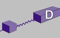
5 Electrons and Nucleus ollide!
6 Timeline DOE provides funding for new facility onstruction egins on EF First Physics Experiments egin GeV Three-Hall Simultaneous Operations GeV Upgrade Development Team Formed Engineering/Design of 12 GeV Machine egins Program to Reach 6 GeV egins May 18th :18 egan the Long Shut Down (LSD) 2012 & GeV Installation Late GeV ommissioning

7 5.5-pass Electron ccelerator Four user facilities (,,, D) Photo Injector Two 1497 MHz Linacs Two Recirculation rcs Dynamic Physics Program Requiring Frequent Energy & Pass hanges >85% Polarization Small Helicity-orrelated eam symmetries erial View
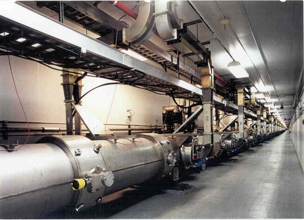
8 EF Tunnel The circumference of the tunnel is ~7/8 mile (1.4 km). Two superconducting linacs (linear accelerator), each ~1/4 mile long. The base of the tunnel is 30 below the surface. The tunnel is 10 high and 13.5 wide.

9 Tunnel Under onstruction

10 In the Tunnel
11 Tunnel with eamlines
12 eamline Under Vaccum EF beamlines are made of stainless steel with diameters from 1 inch to 24 inches. The beamlines are under high vacuum ranging from 10-6 to torr. (Outer space ranges from 10-6 near Earth to in deep space) There are ~450 ion vacuum pumps in the arcs spaced ~ 8m apart. Fast acting and slow acting valves isolate regions of the beamline for maintenance and automatic leak isolation.
13 EF eamline
14 Synchronous Photoinjection Electrons come off a photocathode where a high negative voltage repels them into the beam line. There are two GUNs in the injector. One is a spare. EF GUNs operate at -130 kv.
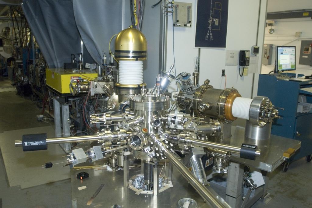
15 EF GUNs
16 Synchronous Photoinjection Near-infrared laser light shines on a Gallium rsenide photocathode. This light is pulsed at 499 MHz. 499 MHz is a sub-harmonic of the fundamental accelerator operating frequency 1497 MHz During three-hall operations, three separate 499 MHz lasers one for each hall are used to generate three interlaced electron beams. ontinuous Wave eam for Physics (W) Pulsed beam for optics tuning (Tune)

17 ontinuous eam Formation
18 Tune Mode (Pulsed) eam Formation
19 hopping System Electron bunches from the 130 kv photocathode gun is sent through a 499 MHz chopper cavity Transverse orthogonal magnetic fields rotate the beam in a circle of ~1.5 cm radius Slits at 0, 120 and 240 degrees allow bunches of electrons to pass hopper slits and laser intensity are individually controlled to regulate currents for Halls, & The three beams are recombined by another 499 MHz chopper cavity
20 hopping System eam hopper #1 RF avity (499 MHz) Lens Master Slit Lens hopper #2 RF avity (499 MHz)

21 hopping System

22 hopping System
23 Injector Layout 5 MeV Dump.
24 cceleration of Electrons The electrons gain energy by placing negative charges behind them and positive charges in front of them. Devices we call cavities are used to set up these charges. avities are hollow shells made from niobium. Jefferson Lab's accelerator uses 418 cavities. Microwaves are directed into the cavities to create the electric charges. The frequency used is 1497 MHz.

25 cceleration of Electrons
26 cceleration of Electrons Electrons eam gains energy when it goes through the cavities
27

28

29 RF avities 7-cell 1497 MHz Niobium SRF avity for EF
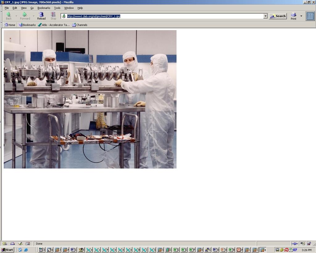
30 Superconductive avities The normal conducting cavities cannot be efficiently operated at high powers due to the heat generated. The heat would lower the efficiency or melt the cavities. When niobium is cooled to very low temperatures, it loses all electrical resistance and becomes a superconductor. Superconductors have no electrical resistance, electrical currents flowing through them do not lose any energy and do not produce any waste heat. The use of superconductive niobium cavities allows EF to operate efficiently.
31 Superconductive avities In order for niobium to become superconductive, it must be cooled by being immersed in a bath of liquid helium at a temperature of -271 (-456 F). This is only 2 above absolute zero. (2 K) The cavities and liquid helium are shielded from the heat of the outside world inside large, very well insulated containers called cryomodules. ryomodules use a combination of insulating methods: n insulating vacuum (convection) Layers of superinsulation (radiant) Thermal shield and thermal clamps (conduction)
32 ryomodules
33 ryomodules There are eight RF cavities in each crymodule ost ~$1 million per crymodule during construction There are 52 and1/4 cryomodules Inside modules, the RF cavities sit in a bath of 400 gallons of liquid helium cooled to 2 Kelvin.
34 HL entral Helium Liquifier (HL) keeps the crymodules super cold. EF has the world s largest 2K liquid helium refrigerator. The cryogenic system holds ~17000 gallons of liquid helium. The HL runs continuously 24/7.
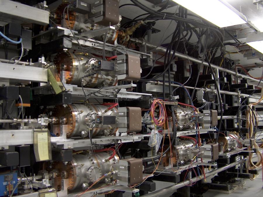
35 EF eamline
36 Magnets Magnets steer, focus and defocus electron beam. There are about 2200 magnets in EF Heaviest magnet is about 20,000 pounds. Magnets can be powered up to 300 mps.

37 Recirculation arcs transport the beam between linacs Low energy beam at the top High energy beam at the bottom 16 or 32 dipoles are used to complete the 180 degree bend rcs

38 6 GeV rc Magnets

39 12 GeV rc Magnets

40 6 GeV rc Magnets

41 Spreaders and Recombiners Spreader and Recombiner sections of the machine connect linear accelerators to recirculation arcs. Magnetic dipoles are powered in series for each rc.


42 Spreader Magnets / Recombiners do the same thing in reverse

43 eamline Girders
44 Extraction of eam ny single experimental hall can receive beam from the first four passes ll three halls may receive beam from the fifth pass Time-dependent transverse kicks are applied to the microbunch structure to selectively direct beams along the correct path ccomplished with RF Separator cavities operating at 499 MHz lso use dipoles and quadrupoles at fixed field strengths to change the path of the beam
45 Extraction of eam Extraction system consists of RF Separators, Septa and Dipole magnets 1-4 pass uses horizontal separation to deflect one beam to halls, or 5th pass uses vertical separation and all 3 halls can have the maximum energy at the same time
46 eam Separators


47 RF Separation asics RF Separator RF separator creates small separation angle (~300 µradians) Y Magnet (septa) Y Magnet Y & Y magnets increase separation eam To Halls Recirculated eam
48 RF Separation Existing (500 MHz) Turn on RF separator Hall Lasers Hall : 500 MHz Hall : 500 MHz Hall : 500 MHz ccelerator Frequency 1500 MHz Separator frequency is 1/3 of the fundamental frequency eam eam to Halls RF Separator avity 500 MHz Recirculated eams eams begin to separate
49 Halls,, 5th Pass Vertical Separation To Halls,, eam ccelerator Frequency 1500 MHz RF Separator avity 500 MHz
50 eam Specifications Just name a few: eam Energy: up to 12 GeV Energy Stability: ~ E-5 eam urrent Range: a few p to 200 u. urrent Stability: < a few percent eam position Stability: -/+ 0.1 mm eam polarization: ~85%
51 How to ontrol the eam eam operations are conducted in the Machine ontrol enter (M) by the Operations personnel using the control software called Extensible Display Manager. ny request for machine parameter changes must go to the M, and the Operations personnel will do the changes. The M is staffed 24/7 during beam operations.

52 Machine ontrol enter

53

54 How to ontrol the eam
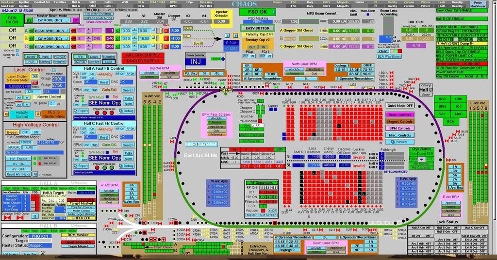
55 HOS

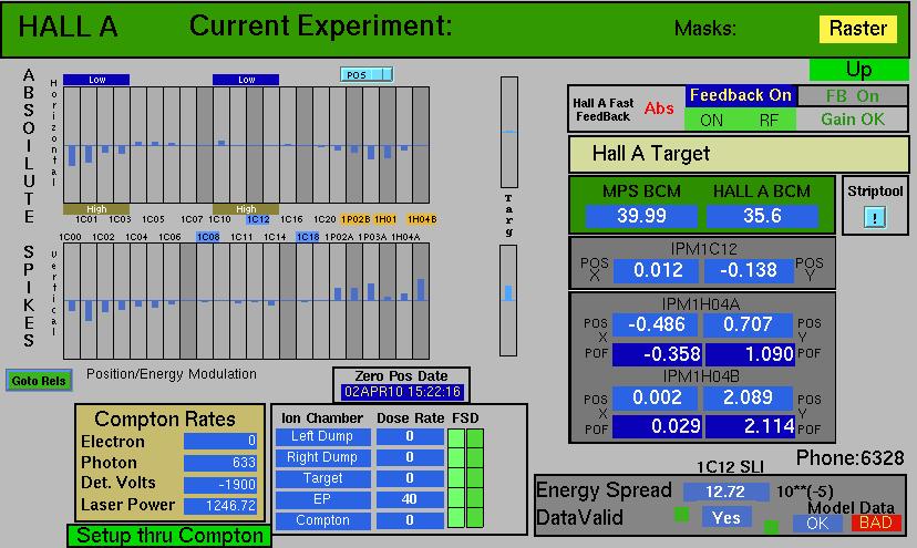
56 eam Position Monitors
57 How to see the eam Energy locks, orbit locks and current locks are used to keep beam stable. Operations personnel monitor the beam using diagnostic tools like beam position monitors (PM), beam current monitors (M), beam loss monitors (LM), synchrotron light monitors (SLM)

58

59 Synchrotron Light Monitor
60 Hall eam
61 Safety Safety has two folds: personnel safety and machine safety. Personnel safety: radiation hazard, electrical hazard, oxygen deficiency hazard, and etc. Machine safety: beam burn-through, beamline component damage, target damage and etc. To ensure safe operations we have safety interlocks and strict policies and rules.
62 pre-12 GeV Upgrade


63 11 6 GeV EF 12 Upgrade magnets and power supplies HL-2 Two GV linacs New cryomodules get new rf zones