Design for Additive Manufacturing
|
|
|
- Melvin Sutton
- 5 years ago
- Views:
Transcription

1 Design for Additive Manufacturing PLM Connections Berlin 2017 Paul Bevan NX Product Marketing Realize innovation.
2 Design for Additive Manufacturing What s limiting your potential? Performance Lead time Design complexity Inventory Weight Cannot make the shape Material properties Serviceability Speed to innovation Design Manufacturing Carbon footprint Page 2


3 Impact of additive design to production processes End-to-end support to design, optimize and produce parts using additive manufacturing processes is revolutionizing the way future structures are developed Siemens is leading in the development of next generation software and processes to enable this shift CES 2017 Divergent 3D 3D Printed Blade Supercar customer Requirements driven design & validation Convergent Modeling TM technology Build processing & validation Design rules & validation Lightweight structure design & optimization Performance Optimization & validation Page 3
 inventory")
4 Additive unlocks the next frontier of possibility Transform thinking from Conventional to Additive REIMAGINE PRODUCTS Reduce weight, material Personalize, customize Expand performance RETOOL MANUFACTURING Add complexity for no cost Reduce steps, setups, tooling RETHINK BUSINESS Accelerate innovation Digital (not physical) inventory Page 4

5 Design for Additive Manufacturing REIMAGINE PRODUCTS Design with Convergent Modeling TM Generative design using topology optimization Lattice structures Design rules for manufacturability Page 5


6 Design for Additive Manufacturing Traditional and new design workflows supported From Traditional Prototyping TO Design Prepare Make Scan to print Scan Simulate Modify Make Optimize to print Design Optimize Validate Make Page 6


7 Design for Additive Manufacturing Convergent Modeling Technology Work directly with facets surfaces and solids Unlimited flexibility to design innovative products No need for reverse engineering Page 7


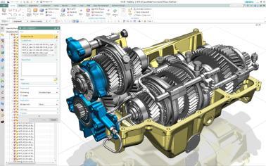

8 Convergent Modeling technology Polygon modeling Scanning Convergent Modeling Design without conversion Additive & subtractive manufacturing Assembly design In-process work piece Topology optimization CAE Mesh Finite element analysis Tooling Motion volume 10x faster than traditional methods! Documentation Page 8


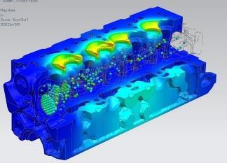
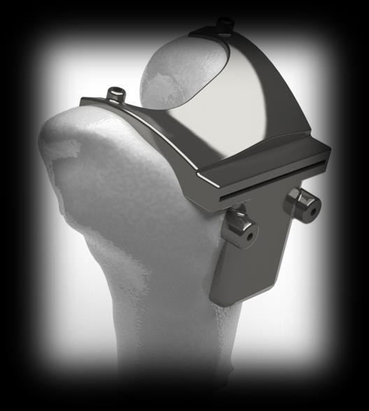
9 Design for Additive Manufacturing Topology Optimization All operations in NX CAD Multiple load cases Optimized model can be refined with Convergent Modeling Page 9

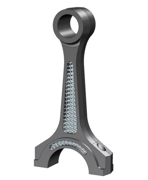
10 Design for Additive Manufacturing Lattices Lightweight components and structural integrity Integrated lattice structure development Complex geometry represented as facets Page 10
 Case Study Roadmap")
11 Design for Additive Manufacturing Topics Current Situation Siemens Solution Common Workflows NX Design for Additive Manufacturing (CAD) Case Study Roadmap Page 11


12 The Current Additive Manufacturing Workflow Design Software Vendor A MFG Software Hardware Vendor B Vendor V Vendor W Vendor V Vendor W Vendor C Vendor X Vendor X Vendor D Vendor Y Vendor Z Vendor Y Vendor Z Vendor E Page 12


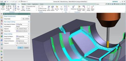
13 The Siemens Additive Manufacturing Workflow Siemens NX Hardware Design using NX CAD Analysis using Simcenter Preparation using NX CAM Vendor V Vendor W Vendor X Vendor Y Vendor Z Page 13
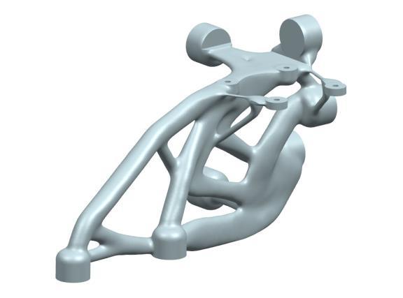
14 Common Workflows Topology Optimized Parts Analyze Optimize Redesign Refine Lightweight Structures Export Lattice Import Trim / Unite Page 14

 Scan Analyze")
15 Common Workflows Scanned Geometry (repair, etc.) Scan Analyze Create/Modify Print Page 15


16 Common Workflows Single Environment Topology Optimized Parts Analyze Optimize Redesign Refine Lightweight Structures Export Lattice Import Trim / Unite Page 16
17 NX Design Status


18 Convergent Modeling Capability in NX 11 NX design can work with facets as any other geometry! Direct use of scan and polygon/facet data without conversion No need for reverse engineering! History based modeling with facet geometry Booleans/Trims Associative wireframe Structure built externally Business value Accelerate concept to production workflows through increased use of polygon/facet data Page 18 Integrated into an NX part
 License nx_additive_design Wall")


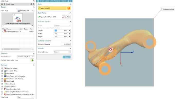
19 Additive Design Rules & Checking (NX ) License nx_additive_design Wall thickness Set threshold for minimum thickness Overhang angle Recognize part regions that require support Printable volume Ensure that part fits within the 3D printer build volume Wholly enclosed volume Identify fully enclosed voids within a part Page 19


20 Lightweight structures design Update NX accelerated investments Fill a solid volume with lattices for part light weighting and material reduction while supporting the required loads License nx_additive_lattice Page 20
21 Demonstrations Optimise Prepare Light Weighted Analysed Page 21

22 Case Study Industrial Burner Tip Redesign
23 Functional-driven redesign of burner tip Conventional Burner Design Burner tip Total length L = 3.4 m Disadvantages: Nested, ring-shaped fluid channels Complex assembly (total length 2 meters) Large length of supply system Many parts, flanges, welds High manufacturing cost / lead time Page 23
24 Functional-driven redesign of burner tip Conventional Burner Design Burner tip Basic Idea: Use pipe connections for Burner tip to reduce complexity of assembly Redesign Tools: Total length L = 3.4 m Disadvantages: Nested, ring-shaped fluid channels Complex assembly (total length 2 meters) Large length of supply system Many parts, flanges, welds High manufacturing cost / lead time Page 24 Siemens NX for CAD-Design CD-adapco STAR-CCM+ for CFD simulation. HEEDS for parametric fluid optimization


25 Functional-driven redesign of burner tip Conventional Burner Design Burner tip Basic Idea: Use pipe connections for Burner tip to reduce complexity of assembly Redesign Redesign for Burner tip using AM design freedom Total length L = 3.4 m Disadvantages: Nested, ring-shaped fluid channels Complex assembly (total length 2 meters) Large length of supply system Many parts, flanges, welds High manufacturing cost / lead time Page 25 Tools: Siemens NX for CAD-Design CD-adapco STAR-CCM+ for CFD simulation. HEEDS/Optimate for parametric fluid optimization New Burner Assembly with redesigned tip Complexity Targeted use of AM to improve system Total length L = 1.7 m


26 Functional-driven redesign of burner tip Page 26 Indicators of Assembly Effort Burner Assembly with Conventional Tip Burner Assembly with Redesigned Tip Number of Parts Number of AM Parts Number of Welding Seams Length of Front Section Length of Rear Section Overall Length of Burner 0 1 > m 1.4m 2.0m 0.3m 3.4m 1.7m


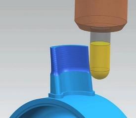
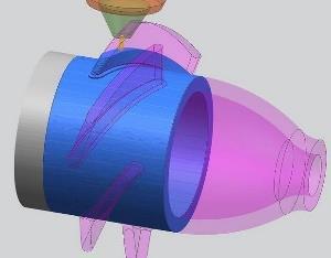
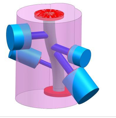
27 Burner Tip Cooling Water Flow Analysis Page 27


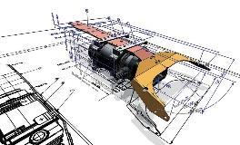
28 HEEDS Multi-Objective Design Exploration Optimize with parameter driven CAD or mesh morphing. NX CAD Geometry STAR-CCM+ CFD Analysis Excel Costing 2. Process Automa on n nodes Rapid attainment of optimal designs considering competing objectives. Multidisciplinary optimization High level of automation. Large ecosystem of integrated solvers In PLM context, configurations are stored and managed and can be reused. 1. Validated CAE Models 5. Sensi vity & Robustness 3. Scalable Computa on 4. Efficient Explora on m cores per node Page 28


29 Oxygen and Water Optimized Fluid Dynamics Page 29

30 Burner Tip Model Page 30
31 NX Roadmap
 Conformal (NX 12) Transitions Geometry preparation tools (fixing/manipulation) Markings/labels (special +")

32 NX Roadmap Convergent Modeling Improvements Lattice structure modeling Unit Cell (NX ) Conformal (NX 12) Transitions Geometry preparation tools (fixing/manipulation) Markings/labels (special + internal) 3MF export Build orientation optimization Multi-color bitmap wrapping Parasolid high-performance lattice representation AM Electro-mechanical design Surface Texture modeling Graded color/material modeling Lightweight Structures Graded Materials Page 32
33 Thank You!