Oil after the Wellhead And the Value of Data
|
|
|
- Paul Chase
- 5 years ago
- Views:
Transcription

1 Oil after the Wellhead And the Value of Data A panel discussion featuring: Emile Coetzer Christine Kemp Rhon Rose 1 Copyright 2015, PPDM Association. All Rights Reserved
2 OBJECTIVE Equip Data Managers with an overview of what happens to the product after the wellhead, so that they can: Serve the Facilities world more effectively Expand their repertoire of offering 2 Copyright 2015, PPDM Association. All Rights Reserved
3 OVERVIEW Introductions Oilfield Left to Right Facilities Data Vernacular Case Studies Risk License to Operate Royalties Knowledge Digitization Discussion 3 Copyright 2015, PPDM Association. All Rights Reserved
4 INTRODUCTIONS Emile Coetzer P.Eng Rhon Rose P.Eng Christine Kemp P.Eng PPDM Support Staff 4 Copyright 2015, PPDM Association. All Rights Reserved
5 OILFIELD LEFT TO RIGHT Very simplified The downstream has thousands of individual types of Subject Matter Experts, I am only qualified in only a few. 5 Copyright 2015, PPDM Association. All Rights Reserved

6 6 Copyright 2015, PPDM Association. All Rights Reserved

7 The Allocation Envelope Losses Fuel Flare and Venting Injection/Evaporation Any Facility Delineation Boundary Inputs Production from Well(s) Outputs from Upstream Facilities Inventory Fudge Factor = Inputs Outputs losses +/- inventory change Called Proration Factor, Measurement Error, etc. OUTPUTS Product Sales Points Inputs to Downstream Facilities
8 OILFIELD EQUIPMENT 8 Copyright 2015, PPDM Association. All Rights Reserved
9 9 Copyright 2015, PPDM Association. All Rights Reserved
10 10 Copyright 2015, PPDM Association. All Rights Reserved
11 FACILITIES DATA VERNACULAR Flow Diagrams Numbering Systems Datasheet Basic Architecture Handover between Project and Operate Phases 11 Copyright 2015, PPDM Association. All Rights Reserved
12 TYPICAL FLOW DIAGRAMS Block Flow Diagrams (BFD) Process Flow Diagrams (PFD) Piping and Instrumentation Diagram (P&ID), or sometimes called a Mechanical Flow Diagram (MFD) Utility Flow Diagram (UFD) (P&ID for the OBL utilities) Material and Corrosion Flow Diagram (MCFD) Raw Water Storage Water Treatme nt Plant Potable Water Storage Chemica l Storage Block Flow Diagram (BFD) Process Flow Diagram (PFD) Sli de AAEL & ESA all rights reserved
 Piping and Instrumentation Diagram (P&ID) Carbon Steel T,= 12343 P=, 3344 Material and Corrosion Flow Diagram (MCFD) Carbon Steel T,= 12343 P=, 3344 Carbon Steel T,= 12343 P=, 3344")
13 TYPICAL FLOW DIAGRAMS (CONT.) Piping and Instrumentation Diagram (P&ID) Carbon Steel T,= P=, 3344 Material and Corrosion Flow Diagram (MCFD) Carbon Steel T,= P=, 3344 Carbon Steel T,= P=, 3344 Carbon Steel T,= P=, 3344 Carbon Steel T,= P=, 3344 Carbon Steel T,= P=, 3344 Carbon Steel T,= P=, 3344 Sli de AAEL & ESA all rights reserved

14 NUMBERING SYSTEMS COMPARISON Source: Max-i Association Sli de AAEL & ESA all rights reserved
15 SAMPLE DATA SHEET : PUMP Pump-Centrifugal Identification Equipment Tag No Classification PUCE ISO14224 RDS ISO15926 Discipline Code M - Mechanical EPISTLE As-built Criticality dependance Attribute Class Specific Requirement Accountable UoM required? required? Users Uses/Location Attributes System No EPC P&ID No EPC Parent Tag No Owner Equipment Attributes Equipment Description Vendor Manufacturer Vendor Model No Vendor Serial No Vendor Date/Batch Vendor Engineering Attributes Diameter Vendor Yes Height Vendor Yes Length Vendor Yes Weight Dry Vendor Yes Wight (operating) Vendor Yes Power Consumption Vendor Yes Rated Capacity Vendor Yes Rated Flow Vendor Yes Rated pressure Vendor Yes Rated pressure Vendor Yes Normal Psuct Vendor Yes Normal Pdis Vendor Yes No of stages Vendor Yes No of vanes per stage Vendor H, M PdM Pgm Body Type Vendor Shaft Sealing Configuration Vendor H, M Radial Bearing Type Vendor Radial Bearing Number Vendor Thrust Bearing Type Vendor Thrust Bearing Number Vendor Normal Operating Speed Vendor Yes H,M PdM Pgm Impeller Material Vendor H Integrity Pgm Casing Material Vendor H Integrity Pgm Rotor 1st Critical Speed Vendor Yes H PdM Pgm Design Code Specifications Vendor PO Number EPC Project Attributes Supplier EPC Order Date EPC Delivery Date EPC FAT/QA Specification Reference Owner Required Documentation General Arrangement EPC yes Sectional Drawing Vendor P&ID Number EPC yes Seal Plan Drawing EPC yes Operating Manual Vendor Maintenance Manual Vendor H, M Repair Manual Vendor H, M FMEA Vendor H Pump Curves Vendor Base and alignment specifications Vendor Condition Monitoring Baselines EPC H, M PdM Pgm Lubricant Specifications Vendor PdM Pgm Coolant Specifications Vendor FAT/Performance Certificates EPC H, M yes Normal Capacity Utilization % EPC H, M Operational Attributes Normal Operating Mode EPC H, M Initial Installation Date EPC H, M Initial Commissioning Date EPC Equipment Criticality Owner Maintenance Strategy No Owner H, M Vibration envelope settings H Yes PdM Pgm BOM Ref No Owner Type of Driver EPC Fluid Handled EPC Integrity Pgm SPIR Ref No EPC Sealing arrangements EPC Additional Components (separate data sheets) and associated equipment yes Transmission EPC yes Instrumentation EPC yes Cooling EPC yes Lubrication EPC yes Valves EPC yes PSVs EPC yes 15

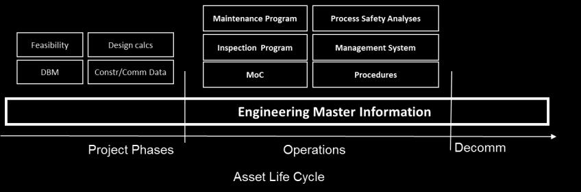
16 16 ENGINEERING INFORMATION ARCHITECTURE

17 HANDOVER DOCUMENTATION Sli de AAEL & ESA all rights reserved
18 CASE STUDIES Risk License to Operate Royalties 18 Copyright 2015, PPDM Association. All Rights Reserved

19 CASE STUDY: RISK 19 Copyright 2015, PPDM Association. All Rights Reserved

20 CASE STUDY : RISK 20 Copyright 2015, PPDM Association. All Rights Reserved
21 CASE STUDY : LTO Within Alberta there are literally 1,000 s of regulatory requirements. Some are super important, others less so, but a culture of ignoring requirements will cause the Alberta Energy Regulator to move you up the escalation ladder. The top of the ladder is loss of your right to operate in Alberta. Measurement Schematics are 4 pages of a 300 page Directive 17 (Measurement). 21 Copyright 2015, PPDM Association. All Rights Reserved
22 HISTORY Only new requirement that came out of discussions with regulator to improve royalty accounting. Alberta formally added requirement in 2010, effective B.C. formally photo copied requirement latter in 2010, effective Saskatchewan adding the same requirement in 2016, effective
23 WHY DO MEASUREMENT SCHEMATICS? Measurement Schematics are a the foundation for avoiding errors and costly accounting and royalty payment re-work. The key is to have them owned and agreed by the Production Accountants, by Operations, and by Engineering/Measurement. A single agreed picture is worth more than 30 separate Excel spreadsheets.
24 LOTS OF REQUIREMENTS/DATA Provincial Requirements cover; Wells (all I will review) Well Test, Satellites and Headers Fuel Measurement and Estimation Flare and Venting Flow Lines Process Equipment Measurement Points Storage Tanks and Vessels Delineation & Facility Sub-types General Layout Updating Frequency Sharing Them
25 WELLS REQUIRED INFO Include all producing, shut-in, water source, and injection/disposal wells. Suspended and abandoned wells are optional. Identify the energy/fuel source Identify if on artificial lift default to Flow Identify VGWL Volumetric Gas Well Liquid default to COND Required to show water source plants that pull water from fresh water sources like lakes and rivers. Must show UWI and type of well (oil, gas etc.). Optional to show well Operator, surface location, working interest, last month s production, etc..
26 WELL UWI S (NOT PPDM S) LSD of the BOTTOM hole location, where the well penetrates the top of the producing zone 100/ W5/02 Location Exception Code; This is used when there is more than one drill per legal subdivision, 100 then 102,103 etc. Event Sequence; Indicates chronological sequence of drilling or completion activities, 00 then 02, 03 etc.

27 WELL TYPICALS VS. VS.
28 SOME OF THE VALUE VECTORS FROM AN ACCURATE MEASUREMENT SCHEMATIC Joint Interest can use them to see what facilities third party wells flow through. HSE can confirm where the dehydrators are that need annual benzene testing. Schedulers know which meters need calibrating (accounting), and which do not (non-accounting). Production Accountants know which wells are on artificial lift and thus might get a royalty break. But; Getting a common, standard view across a company is difficult, though every new user (and shut-down private Excel spreadsheet) strengthens the whole system.
29 CASE STUDY : ROYALTIES & SUSPENDED Two examples of communications failing because of non-standard terms 29 Copyright 2015, PPDM Association. All Rights Reserved
30 EXAMPLE 1 The Alberta Energy Regulator allows Production Accountants to count planned off hours as on when counting production hours. Field data systems accurately track the off and on production hours. Because Alberta has sliding scale royalties more hours mean lower royalties for the same amount of production.
31 EXAMPLE 1 (RESULT) Someone made the connection and the rework spread across industry as one company learned from another. Roughly $100 million in royalty refunds resulted. Who thinks everyone is doing it correctly now??
32 EXAMPLE 2 Within the Alberta Energy Regulator there are at least two definitions of Suspended Well 1. Engineering; drives liability ratings and annual maintenance activities. The regulations force you on suspended status generally after 12 months shut-in, and it takes at least 3 months of continuous production to get off the status. 2. Production Accounting; means you do not need to submit zeros every month for a non-producing well. Prevents any volumes being accidentally reported for a shut-in well. Entirely optional, no direct financial impact. I once 98% aligned these two lists for my company.
33 EXAMPLE 2 (RESULT) Six months latter the CFO called and asked why the number of suspended wells had increased by over 120, resulting in the DD & A amounts had gone up (incorrectly he hoped) by about $ 6 MM/year. They had used the wrong list.
34 KNOWLEDGE DIGITIZATION How do we avoid 100 specialized digital tools (replacing way more Excel spreadsheets) that can not interact? What standards are needed to unite this data? 34 Copyright 2015, PPDM Association. All Rights Reserved
35 TRENDS TOWARDS DIGITIZING MEASUREMENT SCHEMATICS About 7 service providers have built digital versions of tools, designed to replace the traditional Excel, Visio and AutoCAD methods. These are everything from turbo-visio to full data models with data importing and cross checks. There are no agreed standards just some traditional practices.
36 OBSERVATIONS TO DATE A very slow process to change company thinking or develop new standards. Most companies use very little of their available digital knowledge. Knowledge silos are common. Companies learn and forget the same thing many times and at the same time within the organization.
37 MY CHALLENGE As we learn about bad data/missed opportunities we digitize them, so they do not become unlearned. In this the earlier examples we perhaps add a test to look for wells that have reported zero production for the last 10 months and have not been suspended, or a test to look for wells that have partial month production too often. But would not agreed definitions of suspended and Production Hours, and creation of new terms to cover the other situation, also help?
38 DISCUSSION 38 Copyright 2015, PPDM Association. All Rights Reserved
39 SUPPORT SLIDES 39 Copyright 2015, PPDM Association. All Rights Reserved

40 PRIMARY SEPARATION 40 Copyright 2015, PPDM Association. All Rights Reserved

41 CARBON CHAINS AND BASIC DISTILLATION COLUMN 41 Copyright 2015, PPDM Association. All Rights Reserved

42 OIL GATHERING & REFINING Image provided by 42 Copyright 2015, PPDM Association. All Rights Reserved

43 SAGD Image provided by 43 Copyright 2015, PPDM Association. All Rights Reserved

44 OILSANDS Image provided by 44 Copyright 2015, PPDM Association. All Rights Reserved
45 MEASUREMENT SCHEMATICS AS DATA Rhon B.F.M. Rose Measurement Guru, Facility Studio PPDM Calgary Conference October 2015
46 WELLS OIL EXAMPLE Note the suspended well
47 LEGEND
48 Level of Effort FEL ILLUSTRATION Mismanaged FEL Unsuccessful Projects Well-managed FEL FEED Phase Construction & Commissioning Successful Project Inadequate FEL Project Start Time Start-up Sli de AAEL & ESA all rights reserved
49 TYPICAL WORK MANAGEMENT PROCESS Reliability Design Work Analyze Work Everyone Identify Work Management Prioritize Work Review Work Planning & Scheduling Plan Work Schedule Work Record Work Maintenance Execute Work Warehouse Spares 49

50 THANK YOU 50 Copyright 2015, PPDM Association. All Rights Reserved