VMS Vibration Monitoring System. 2017, Logic Elements s.r.o.
|
|
|
- Austen West
- 5 years ago
- Views:
Transcription
1 VMS Vibration Monitoring System 2017, Logic Elements s.r.o.
2 Blade Vibration Monitoring VMS Platform VMS Case Studies
 with")
3 Motivation The free standing and especially shrouded or bandaged blades are often used in turbomachines of large capacity, mainly in steam turbines. To avoid accidents with extensive economic losses, there appears an urgent need to equip at least the last stage of low pressure turbine (with respect to the dimensions of the installed blades) with monitoring to provide information of blades vibration, their damage and residual lifetime.

4 Double casing steam turbine 150 MW Overview example Last Stages of LP

5 Blade Tip Timing measurement principle

6 Blade Tip Timing measurement principle
7 Blade Vibration Monitoring VMS Platform VMS Case Studies

8 VMS Description & Features

9 VMS Signal Chain

10 Sensor (Inductance Sensor, Temperature measurement included) Optimally suitable for the use at all kind of turbomachines. Measuring quantities includes: Blade vibration measured from Time of Arrival signals Blade untwisting and angle between leading and trailing edge Blade lean Shaft speed Air gaps between rotating and stationary parts (indirect measurement has to be calibrated) Temperature measurement Torsional shaft vibration Parameter Value Cable length 15 m Temperature 225 C Head diameter 14 mm Flange direct Optionally includes PT100 temperature sensor
 1 Analog Input (sensor) 1 Digital output (RS485) 1 Analog Output (+/- 10V) Trigger Level Selection (+5V, 0V, -5V) Signal Gain Control (from 1x to 20x)")
11 Sensor Amplifier (VMS-1501) With the VMS-1501 you can choose a couple of output signals to use such as Triggered differential digital signal, Differential raw analog signal from the sensor or both. Functions and benefits: DIN mounting (3 modules) 1 Analog Input (sensor) 1 Digital output (RS485) 1 Analog Output (+/- 10V) Trigger Level Selection (+5V, 0V, -5V) Signal Gain Control (from 1x to 20x) Input Impedance Control (from 100R up to 1600R) Power Supply range from +-12V up to +- 15V
 Sampling frequency 100MHz /ch Ethernet communication to server 100 Mbps interface speed USB port for settings and diagnostics")
12 VMS Description & Features Platform for measurement of blades vibration of steam turbine. 16x channel for sensors High accuracy (12-bit resolution) Sampling frequency 100MHz /ch Ethernet communication to server 100 Mbps interface speed USB port for settings and diagnostics RS485 (galvanic isolation) for integration of 3 rd party devices Width 19, height 3U, depth 240 mm

13 BTT Data Acquisition Card (VMS 1301) VMS-1301 is designed to process high speed signals. Blade vibration measured from Time of Arrival signals Blade untwisting and angle between leading and trailing edge Blade lean Shaft speed Air gaps between rotating and stationary parts (indirect measurement has to be calibrated) Temperature measurement (with VMS-1601)

14 VMS Controller (VMS-1201) The VMS-1201 Controller card is a component which is capable to perform parallel computing, communicate with backend VMS server, control the system, and configure the channels USB serves for the system maintenance and service purposes. Dedicated software tools must be used. RJ45 Ethernet middle RJ45 connector is the main communication interface with the back-end server. It is a key point in communication with the system. RJ45 RS485 bottom RJ45 connector is dedicated for special kind of applications when a third-party system is supposed to be connected.


15 Backplane (VMS-1101) Parallel data access from MCU card to Front End cards. Dedicated LVDS line for precise time measurement of blades. Up to 16 Front End cards in one rack 19 box. One MCU card slot. Power supplies 100 W or 130 W. DIN41612 Connectors.

16 Temperature Sensor Preamplifier (VMS-1601) Inductance Sensors are equipped by PT100 temperature sensor. Temperature data are periodically measured and stored for further analysis. The main purpose is to monitor temperature in the turbine. When steam temperature is higher than 200 C than sensors can be damaged. Temperature Sensor Module contains up to 6 channels.
 to online monitoring of turbine system performance, including remote communication.")
17 VMS Software Software has been developed to meet the full range of blade vibration monitoring demands, from receiving and interpreting signals from the sensors (as processed by the pre-amp through the data console) to online monitoring of turbine system performance, including remote communication. The major components of VMS software from Logic Elements are: LE-VMS VMS SETUP LE-VMS VMS COMPUTING CORE LE-VMS VMS ANALYSIS LE-VMS VMS WEB CLIENT


18 VMS SETUP VMS SETUP software is designed to capture non-contacting blade tip timing sensor data. Main features include: The software allows the user to view and change conditioning and triggering parameters for each measured channel - sensor (gain, edge, arm, trigger, etc.). The Logger - virtual oscilloscope allows the user to view analog sensor signals and time of arrival while simultaneously adjusting conditioning and triggering. The time of arrival from each blade is stored to internal database Multiple rotors are supported.

19 VMS ANALYSIS Sensor Status (correct number of pulses, arrival variability). Sensor Location Determination, based on user configuration or interblade spacing Circumferential Fourier fit (i.e. Order Tracking) using 3 or more sensors. Blade-by-blade viewing Results can be exported to a Campbell or SAFE diagram User-configurable data smoothing and processing features. Spectrogram display. Full 0-1kHz frequency analysis (identification of blade frequencies and nodal diameters). Non-integral Circumferential Fit performed for single blade amplitudes. Results can be exported to a Campbell or SAFE diagram.


20 VMS WEB CLIENT VMS WEB CLIENT provides remote access to VMS data and analysis results long-term trending of monitored synchronous/asynchrounous phenomena available in any web browser no installation needed offers a platform to store the diagnostic templates, graphs and analysis results for repeated analysis with new data or for sharing them with co-workers alarm management and settings user defined data visualization

21 Blade Vibration Monitoring VMS Platform VMS Case Studies
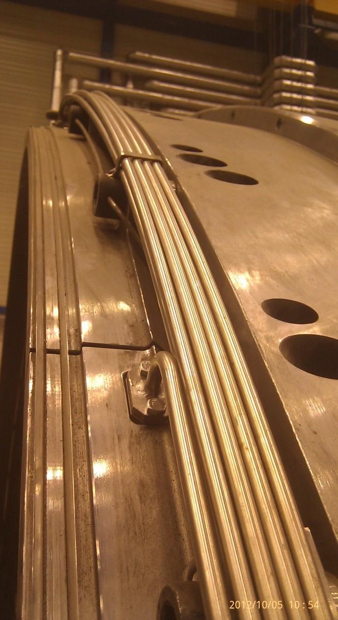

22 Sensor Installation in TG 300MW


23 VMS installation in NPP steam turbine 2x250MW 1st TG VMS Unit 2nd TG VMS Unit VMS Server

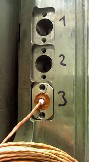
24 Installation of Blade Ejection Sensors

25 Shrouded Blade Tip Sensing by the Optical Probe Measured part of the shroud Optical signal from the passing blade

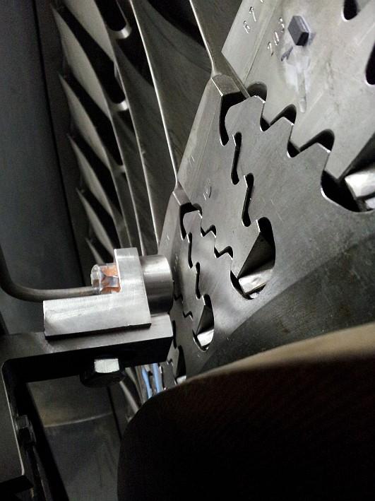
26 Blade Tip Sensing with Use of Optical and Inductive Probe 3000rpm operation Line of measurement Inductive probe Optical probe
27 Temperature measurement during backpressure changes (measured with VMS-1901) 27
28 Influence of Operational Parameters on Blade Vibration (condenser back-pressure) Decrease of blade natural frequency due to the rising backpressure Identification of blade natural frequency in TG operation using VMS Blade temperature increase Increase of blade natural frequency due to decreasing backpressure
29