John Jay College Expansion Project
|
|
|
- Isaac Flynn
- 5 years ago
- Views:
Transcription

1 Technical Report #1 Michael Hopper Mike AE Consultant: Dr. Lepage [Type the company name] September 29 th, 2008 Technical Report #1
2 Table of Contents Executive Summary.3 Introduction.4 Structural System.6 Foundation.6 Floor System.8 Columns 8 Lateral System.9 Codes and References 12 Materials.14 Gravity and Lateral Loads 16 Gravity Loads.16 Lateral Loads..18 Wind Loads..18 Seismic Loads.25 Typical Floor Framing Spot Checks 27 Metal Decking 27 Typical Composite Beam 28 Typical Composite Girder.29 Typical Column.29 Typical Perimeter Plate Hanger 30 Conclusion..31 Appendix A.32 Appendix B.34 Appendix C.37 Appendix D.38 Appendix E. 39 Appendix F
3 Executive Summary In the first technical report for the the building is introduced through a brief explanation of function and a detailed description of the structural system including foundations, floor framing systems, columns, perimeter plate hangers, and lateral systems. A list of materials and governing building codes are also provided. Gravity loads are calculated using ASCE 7 05 and are very close to the Building Code of the City of New York s required gravity loads. Wind and Seismic loads are also calculated using ASCE 7 05 and are compared to the structural engineer s lateral loads. It was determined that the seismic loads were fairly close, while the wind loads calculated in this report are larger than wind loads determined by the NYC Building Code. A typical bay was analyzed and designed for gravity loading. This resulted in verification of the member sizes listed in the structural drawings


4 Introduction N Figure 1 Site plan This major expansion project in Manhattan will unify the City University of New York s John Jay College of Criminal Justice into a one block campus that will demonstrate the transparency of justice. The design includes a mid rise tower situated on the west side of the site, which will contain classrooms, forensic laboratories, department offices, several student lounge spaces, a moot courtroom, a café, and a student bookstore. A mid rise structure connects the expansion to Haaren Hall (the existing building) and calls for a multi level grand cascade, which also serves as a main lounge space for students. The connection also contains classrooms, a black box theater, and two cyber cafes. A landscaped roof accommodates outdoor lounge and dining areas, and an outdoor commons. Amtrak tracks cross the south west corner of the site, which is beneath the mid rise tower. This restriction led to a unique structural solution to transfer over the tracks. Floors 1 through 5 are transferred over the tracks using built up steel transfer girders and floors 6 through 14 are hanging from perimeter plate hangers supported at the penthouse level by transfer trusses that are one story tall. These trusses then transfer the loads to a braced frame core


5 See Figure 1 and Figure 2 for elevation views of the John Jay College Expansion Project. Figure 2 North Elevation Figure 3 West Elevation 5 4 7


6 Structural Systems Foundation: The site of the is sloping from the east down to the west, and therefore the foundation system is split into two levels. This caused the designers to use various types of foundation systems to support the structure. The northern half and south eastern corner of the building is primarily supported on drilled caissons ranging from 18 to 36 in diameter. These caissons are embedded up to 14 0 into the bedrock below. On the south western corner of the site, columns are supported by reinforced concrete piers of dimensions ranging from 20 x20 to 72 x42. These concrete piers are then supported by individual column footings ranging in sizes of 3 0 x3 0 to 9 0 x9 0 that are bearing on bedrock. See Figure 4 and 5 for locations of concrete piers and caissons. Caissons Concrete Piers Figure 4 West Expansion Foundation Plan 6 4 7


.")
7 Caissons Concrete Piers Figure 5 East Expansion Foundation Plan The first floor framing system is constructed using a two way reinforced concrete slab on ground that is 6 thick. The slab is spanning to grade beams, which then frame into the concrete pier caps or concrete caissons. The perimeter of the building is enclosed with a reinforced concrete wall that varies in thickness from 12 to 20. The also has a major site restriction: Amtrak tracks cross the south western corner and west side of the site (see Figure 6). Loads from the 1 st through 5 th levels are transferred over the tracks by built up box girders of up to 3 2 deep with 4 thick flanges. The tracks are enclosed with 10 thick hollow core pre cast planks to minimize the amount of time the tracks are delayed for construction

, consists of W36 girders spanning 68 4 with infill beams spaced typically at 11 4 on center.")
8 Amtrak Tracks Figure 6 Amtrak Foundation Plan Floor System: The floor system of the is a composite system with the most typical bay size being 30 0 x ½ light weight concrete and 3 metal decking typically span 12 2 to W14x22 or W16x26 infill beams. ¾ diameter x 5 ½ long shear studs allow composite action between the floor system and beams. Infill beams span into W shape girders of varying sizes or two back to back MC shapes. Framing of the cascade, which connects the tower to the existing building (Haaren Hall), consists of W36 girders spanning 68 4 with infill beams spaced typically at 11 4 on center. See Appendix A for typical floor framing plans. Columns: Typical gravity columns for the are W14 s. Lateral columns have a significantly heavier W14 section than the gravity columns due to the perimeter tensile loads transferring to the braced core at the penthouse level and 8 4 7

9 to resist lateral loads. Perimeter plate hangers supporting the 6 th through 14 th floors range in size from 1 x12 to 2 x20. Splices of the plate hangers occur at every two levels using 1 1/8 diameter A490 bolts. Lateral system: The 14 story tower of the expansion project has a large centralized braced frame core (see Figure 7 and 8). This braced frame surrounds the vertical shafts of the building, such as elevator shafts, stairwells, mechanical shafts, and plumbing. Columns of the braced frames are heavy W14 sections and the beams are typically W16 sections. HSS 6x6x3/8 are typically used for diagonal bracing at the 13 th level and HSS 8x8x3/8 are used for the diagonal bracing at the 1 st level. Reinforced concrete walls span between the caissons and concrete piers at the foundation of the lateral system. Figure 7 Location of Lateral Force Resistance Systems (Braced Frames) in tower 9 4 7

10 Figure 8 South Elevation of the Braced Core in the 14 story tower The lateral system for the 5 story cascade is also a braced frame which encases the buildings vertical circulation (see Figure 9). Columns of these braced frames are lighter W14 sections than the 14 story braced frame and the beams are W16x31 s and W21x94 s. Diagonal braces are typically 2L 6x4 s with varying thicknesses
.")
11 Figure 9 Location of Lateral Force Resistance Systems (Braced Frames) in the 5 story cascade Braced frames were chosen to resist the lateral forces because they are more efficient than moment frames (relatively stiff system without the high cost of moment connections). The centralized core, which is very typical in high rise construction, allows for the diagonal braces to be enclosed by partitions. Reinforced concrete shearwalls could be used around the core of the building in place of braced frames, but in New York City steel workers will not work with any crews above them, which would lead to complicated scheduling for construction
12 Codes and References Design Codes: National Model Code: The Building Code of the City of New York with latest supplements Structural Standards: ASCE 7 02, Minimum Design Loads for Buildings and other Structures (used for cladding wind loads) Design Codes: AISC LRFD 1999, Load and Resistance Factor Design Specification for Structural Steel Buildings AISC ASD 1989, Specifications for Structural Steel Buildings Allowable Stress Design and Plastic Design (used for the design of Braced Frames and Penthouse level Transfer Trusses) ACI , Building Code Requirements for Structural Concrete Deflection Criteria: Gravity Deflections: Live load deflections of beams < 60 are limited to L/500 or ¾, whichever is smaller Live load deflections of beams 60 are limited to L/500 or 1 3/8, whichever is smaller Live load deflections of beams supporting elevator sheave beams are limited to L/1666 Total load deflections of beams and lintels supporting masonry is limited to L/600 or 0.3, whichever is smaller
13 Lateral Deflections: Thesis Codes: Total building sway deflection for wind loading is limited to H/500 Total building sway deflection for seismic loading is limited to H/260 Interstory shear deformation for wind loading is limited to (story H)/400 Interstory shear deformation for seismic loading is limited to (story H)/260 National Model Code: 2006 International Building Code Structural Standards: Design Codes: ASCE 7 05, Minimum Design Loads for Buildings and other Structures Steel Construction Manual 13 th edition, American Institute of Steel Construction ACI , Building Code Requirements for Structural Concrete, American Concrete Institute
14 Materials Structural Steel: Wide Flanges and Tee Shapes.ASTM A572 or A992, Grade 50 Channels and Built Up Sections...ASTM A572, Grade 50 Pipes.ASTM A501 or A53, Types E or S, Grade B Tubes.ASTM A500 Grade B Angles..ASTM A36 Connection Plates ASTM A36 Metal Decking: 3 and 2 Composite Deck..Fy = 40 ksi, 20 Gage Minimum Headed Shear Studs: ¾ diameter...astm A108, Type B Welding Electrodes: E70XX.tensile strength of 70 ksi High Strength Bolts: ¾ and 7/8 Bolts.ASTM A325 1 and 1 1/8 Bolts..ASTM A490 Cast in Place Concrete: Caisson Caps and Grade Beams..f c = 4000 psi Caissons and Piers f c = 6000 psi Slabs on Ground and Footings.f c = 4000 psi Walls..f c = 4000 psi Slabs on Deck.. f c = 4000 psi light weight concrete unless noted on drawings Reinforcement: Reinforcing Bars...ASTM A615, Grade 60 Caisson #18 Reinforcing Bars ASTM A615, Grade
15 Welded Wire Fabric: D4.0 and larger..astm A497, Fy = 70 ksi W4.0 and smaller..astm A185 (Fy = 65 ksi > W1.2, Fy=56 ksi < W1.2) Deformed Bar Anchors..ASTM A496, Fy = 70 ksi
16 Gravity and Lateral Loads ASCE 7 05 was used for both gravity and lateral loads. Gravity Loads: Construction Dead Loads: Typical floor Construction: 3 Metal Decking: 20 Gage Minimum 3 psf 3 ½ Lightweight Concrete Slab (115 psf) 48 psf Allowance for Self Weight of Steel Framing 7 psf Total CDL for Floor System Design: 51 psf Total CDL for Seismic Calculations: 58 psf Mechanical and Mezzanine floor Construction: 3 Metal Decking: 20 Gage Minimum 3 psf 4 ½ Normal weight Concrete Slab 75 psf Allowance for Self Weight of Steel Framing 7 psf Total CDL for Floor System Design: 78 psf Total CDL for Seismic Calculations: 85 psf Superimposed Dead Loads: Typical floor Construction: Fireproofing Finishes Partitions Ceiling Mech. & Electrical Distribution Total SDL: 2 psf 5 psf 20 psf 5 psf 5 psf 37 psf
17 Live Loads: Typical Spaces: ASCE 7 05 Design (NYC Building Code) Classrooms 40 psf 60 psf Offices 50 psf 50 psf Lobbies & Corridors 100 psf 100 psf Cascade 100 psf (assume corridor/lobby/bleachers) 100 psf Stairs 100 psf 100 psf Assembly areas (moot 60 psf (fixed seats) court and quad spaces) 100 psf (movable seats) 100 psf Roof 20 psf 30 psf Heavy Mechanical Equipment: 6 th, 7 th, & 8 th Floor: Increased loads in laboratory spaces 100 psf (assumed) Penthouse Mezzanine Level 63 kips (Total load) Penthouse Level 853 kips (Total Load) Wall Loads: Curtain Wall 1 6 Thick Reinf. Conc. Wall (@ Foundation) 25 psf 225 psf Snow Loads: Ground Snow Load Flat Roof Snow Load Rain on Snow Surcharge Tower Roof Drift 20 psf 22 psf 5 psf 25 psf Commons Drift 70.6 psf (For calculation of snow loads, see Appendix E)
18 Lateral Loads: Wind Analysis: The wind loads for the were analyzed using Method 2 listed in Chapter 6 of ASCE Details of the analysis can be found in Appendix C of this report. Loads were calculated using the height and widths of the 14 story tower, and then the lower level pressures were applied to the 5 story cascade section of the project. It was determined that the pressures in the North South direction were slightly larger than in the East West direction. The base shear also controlled in the North South direction due to the large façade area of the cascade connecting the tower to Haaren Hall. Below in Table 1 are tabulated values of wind pressures at each floor level. Table 2 displays lateral loads, shears, and moments created at each level by the wind pressures. Wind Pressures Level Height Above ground Kz qz N S E W (ft) (psf) (psf) T.O. Parapet Roof Penthouse Windward Leeward All All Table 1 Wind Pressures
19 Wind Forces Level Height Above ground Load (kips) Shear (kips) Moment (ft kips) (ft) N S E W N S E W N S E W Roof Penthouse Total Table 2 Wind loads, shears, and moments at each level As you can see in table 2 above, the base shear of 1968 kips in the north south direction controls. This is expected due to the large façade area in the north south direction

20 Wind Pressure Diagrams: Figure 10 North South wind pressure diagram

21 Figure 11 East West wind pressure diagram
22 Wind Load Diagrams: Wind pressures were applied to the building s façade and distributed to floor levels by tributary area. Floor diaphragms are assumed to be rigid and transfer wind loads to the braced frames at the building s core. See figures 12 and 13 for the distribution of wind loads to the lateral systems. Figure 12 North South Wind Force diagram
23 Figure 13 East West Wind Force Diagram Response to Calculated Wind Loads: The calculated windward pressures using ASCE 7 05 are comparable to those used by the structural engineer of record. The Building Code of the City of New York requires a wind pressure of 20 psf for feet above the ground and 25 psf for feet above the ground. Calculated pressures at level 7, which is above the ground, is 20.1 psf in the east west direction using ASCE 7 05 and the pressure at the roof level is 25.6 psf in the east west direction using ASCE These values are very close to the pressures in the New York City Building Code, however, when leeward suction pressures are added, method 2 of ASCE 7 05 becomes a more conservative approach for calculating wind loads. See Table 3 for a comparison between windward pressures and Table 4 for a comparison between total pressures. Base shear values from the structural engineer verify the prediction that ASCE 7 05 is more conservative than the New York City Building Code. A base shear of 1106 kips in the east west direction and 1329 kips in the north south direction were calculated by the designers. These values are significantly smaller than the base shears calculated using ASCE 7 05 for this report, which are presented in Table
24 Height ASCE 7 05 Method 2 New York City Building Code N S (psf) E W (psf) (psf) 101' 8" ' 8" Table 3 Comparison between windward pressures using ASCE 7 05 and the Building Code of the City of New York Height ASCE 7 05 Method 2 New York City Building Code N S (psf) E W (psf) (psf) 101' 8" ' 8" Table 4 Comparison between total pressures using ASCE 7 05 and the Building Code of the City of New York
25 Seismic Loads: The seismic loads for this report were calculated using chapters 11 and 12 in ASCE It was determined that the equivalent lateral force procedure could be used for the. This seismic analysis includes dead loads from typical floor construction, heavy mechanical equipment, the commons roof (green roof on cascade), and wall weights. These dead load calculations are available in Appendix B. See Appendix D for all seismic calculations and assumptions used. Below in Table 5 is a load distribution table. Lateral forces are assumed to transfer through rigid floor diaphragms to the steel braced frames. Seismic forces for the John Jay College Expansion project are less than the forces generated by wind pressures. Level Story Weight Height k w x h x C vx Lateral Force Story Shear Moment w x (Kips) h x (ft) F x (kips) V x (kips) M x (ft k) Roof Penthouse Total Table 5 Lateral forces, story shears, and overturning moments Response to Calculated Seismic Loads: The total base shear from the structural engineer s seismic analysis is 738 kips. This value is comparable to the base shear of 819 kips as calculated above in Table 5. After reviewing the structural engineer s seismic calculations, the following discrepancies account for the difference is base shears: The structural engineer used the New York City Building Code for their seismic load calculations, while ASCE 7 05 was used for this report. This resulted in a base shear coefficient of from the NYC Building Code, and a base shear coefficient of from ASCE
26 The structural engineer was more accurate when calculating the area of each floor. Total floor areas of the building provided by the structural engineer are approximately 682,000 square feet which resulted in a total weight of 53,832 kips. Floor area calculations for this report resulted in a total of approximately 711,000 square feet. This led to a total weight of 81,866 kips. This report included the weight of heavy permanent equipment at the penthouse level, heavy dead loads for the commons roof (green roof), and heavy loadings in laboratory spaces for the seismic weight. These additional loadings were not used by the designers. It is very typical for lateral systems of tall buildings in New York City to be controlled by wind forces, therefore little efforts are put into seismic calculations by practicing engineers. Even with the conservative approach used in this report, the wind loads still control the lateral forces for the
27 Typical Floor Framing Spot Checks Figure 14 Typical 30 0 by bay Above in Figure 14 is a typical bay that was analyzed. Typical infill beam sizes for the are W16x26, which frame into typical girder sizes of W24x68. Girders and spandrel beams are supported by either columns or perimeter plate hangers. Metal Decking: It was determined from the structural design criteria, general notes for each floor, and in the specifications that the metal decking chose by the structural engineer is 3 deep, with a 40 ksi minimum yield strength, and a minimum thickness of 20 gage. The following table was taken from United Steel Deck for a 3 deep deck with a yield strength of 40 ksi:
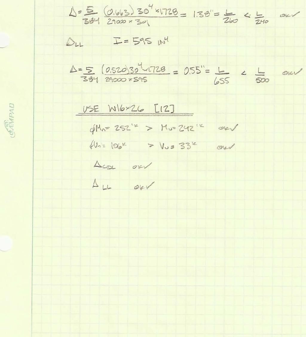
28 Maximum un shored spans for this metal decking with a 6 ½ thick slab are highlighted in red above. Typical clear spans between the W16x26 infill beams are feet and the decking clears 3 spans. Therefore, the decking is adequate to span between infill beams. The following table was also taken from United Steel deck and displays the maximum service live load per square foot of metal decking: As you can see in the table above, the selected metal deck can support 215 pounds per square foot for a 12 ½ foot span with a 6 ½ concrete slab. The total load that the decking needs to support is 188 pounds per square foot and therefore the metal decking is adequate for use. See Appendix F for supporting calculations. Typical Composite Beam: Typical composite beam sizes for the are W16x26 [30]. Figure 14 displays the location of these beams which are typically spaced at feet and span 30 feet. These beams were checked for bending, shear, and deflection and the design calculations are in Appendix F. After designing a typical composite beam, it was verified that a W16x26 meets all requirements for strength and serviceability. A minimum number of shear studs of 12 was calculated to ensure composite action between the floor slab and steel beam. Although this size meets all design requirements for strength and serviceability, Mu/ΦMn=0.98 (see Appendix F). This means the beam is adequate, but common engineering practice would be to add more shear studs to increase the bending capacity of the composite beam. This approach was adopted by the structural engineer, as they have provided 30 shear studs for this beam per the construction documents. Also, by supplying 1 shear stud per foot of beam, the metal decking can support more superimposed live load than a beam with greater shear stud spacing
29 Typical Composite Girder: After analyzing a typical composite girder, it was determined that the minimum beam size to resist the required loading is a W24x55. This beam size was selected by determining the minimum beam size required to exceed the minimum construction dead load deflection criteria of span/240. Once this size was selected, 44 shear studs were required to create composite action between the floor slab and beam. An area of concern is the bending capacity of this member, where Mu/ΦMn=0.95. As mentioned above, it is common in engineering practice to increase the amount of shear studs or increase the beam size to allow for unforeseen conditions. The structural engineer took this approach for design and used a W24x68 [42] for typical composite girders. See Appendix F for all design assumptions and calculations. Typical Column: Typical columns for the expansion project support floors 2 through 5 and are spliced at level 3. Column load takedowns are available upon request, but service and factored compressive loads are listed in Appendix F for reduced and unreduced live loads. Table 4 1 of the Steel Construction Manual was used to size columns. Un braced lengths of the column were determined by floor to floor heights and columns were assumed to be pinned at the top and bottom. Live loads were reduced for design with the exception of level 5 due to an un reducible cafeteria live load of 100 psf. See Appendix F for the complete design procedure. Using the assumptions listed above, the top portion (levels 3 through 5) of column M/7 was sized to be a W14x61 and the bottom (levels 1 through 3) was sized to be a W14x61. Column M/7 is listed in the structural drawings as a W14x74 at the top and a W14x82 at the bottom, which are both slightly larger than the columns designed for this report. There are many possible reasons for these discrepancies, but it is most likely that the designer increased the column size to account for any unexpected future loads. For example, typical spaces supported by columns are classrooms, but there are also many laboratory spaces at higher levels in the building supported by plate hangers. If the school needs to move some laboratories to lower levels, the columns may have the capacity to support loads from heavy machinery. Another possible reason for the different column sizes is that the structural engineer could have been conservative and used un reduced live loads for the entire column because the cafeteria loading at level 5 is un reducible
30 Typical Perimeter Plate Hangers: Floors 6 through 14 of the tower are hanging from perimeter plate hangers which transfer gravity loads from the floors up to transfer trusses at the penthouse level. The plate hangers are 50 ksi steel and are spliced at every two levels using 1 1/8 diameter ASTM A490 bolts. A typical load take up is listed in Appendix F for service and factored loads with both reduced and un reduced live loads. To design the plate hangers, required tensile areas of 50 ksi steel were calculated at level 13 (point of maximum load) with reduced live loads. Tensile areas were determined for two limit states: yielding and rupture, in which the effective area for rupture was assumed to be 75% of the gross area to allow for splicing connections. See Appendix F for plate hanger design calculations. The design of plate hanger L/7 (same location in plan as column M/7) at the 13 th level of the resulted in a tensile area of inches squared, which was controlled by rupture. This same plate hanger is shown on the structural drawings as a 1 ½ by 18 plate, resulting in 27 inches squared. These differences between plate areas can be explained by the progressive collapse analysis performed by the structural engineer. The designers wanted to ensure redundancy in the hanging structure, so the plate hangers and transfer trusses were designed to prevent collapse in the event of the removal of a plate hanger. A similar calculation is listed in Appendix F using the take up loads and resulted in an area of 25.4 inches squared, which is comparable to the 27 inches squared provided by the structural engineer
31 Conclusion In the first technical report of the, the existing building conditions are investigated. A detailed description of the buildings foundations, floors systems, columns, plate hangers, and lateral system, as well as typical floor framing plans and other images were provided to introduce the building and structure. Gravity loads were calculated from ASCE 7 05 and were used to design a typical bay in the expansion project. Lateral loads were also examined using ASCE 7 05 and were compared to the forces used by the original designers. Spot checks for the typical bay verified the structural engineer s results shown in the structural drawings. It was determined that the designer was conservative and that each member analyzed in this report had adequate capacity. Seismic loads calculated in this report were close to values calculated by the structural engineer despite having used a different code for this report. However, the base shears caused by wind loading were substantially larger for this report than calculated by the structural engineer. This difference is explained by the difference in codes. Method 2 in ASCE 7 05 is a more conservative approach than the Building Code of the City of New York, and therefore the larger base shear calculated in this report is acceptable

32 Appendix A Typical Floor Plans Typical Tower Framing Plan

33 Typical Cascade Area Framing Plan

34 Appendix B Dead Load Calculations
35 35 4 7
36 36 4 7
37 Appendix C Wind Analysis V= 110 mph K d = 0.85 K d = 1.85 K d = 2.85 Exposure: B C p Value N S E W Windward wall Leeward Wall Side Wall Gust Effect Factors N S E W B L h n Structure: FLEXIBLE FLEXIBLE g R z I z L z Q V z N R n R h n= R B n= R L n= R G f
38 Appendix D Seismic Analysis The following table displays the assumptions used to calculate the seismic forces using ASCE S s = 0.35 %g S 1 = 0.06 %g Occupancy Category= III Site Class= C (Assumed) F a = 1.2 F v = 1.7 S ms = 0.42 S m1 = S DS = 0.28 S D1 = T a = T s = < T a SDC= B Table SDC= B Table SDC= B Can use Equivalent Lateral Force Procedure T s = R= 6 Special steel concentrically braced frames I= 1.25 Occupancy Category III T a = C u = 1.7 T L = 6seconds C s = 0.01 < Governs C s = k= 1.36 W= Kips V= 819 Kips
39 Appendix E Snow Loads The following snow loads were calculated from ASCE Snow loads were calculated for drifts at typical parapets and for drifts on the commons roof against the tower. Snow Loads P g = 20 psf C e = 1.1 Terrain Category C C t = 1 I= 1.1 Assume Category III P f = 22 psf Rain on Snow Surcharge= 5psf Snow Drifts γ= pcf h c parapet = 1.50 ft h c cascade roof = ft h d = 4.25 ft h d = 1.33 h c /h b parapet = 1.14 h c /h b cascade roof = 7.55 w parapet = w cascade roof = DRIFT parapet : Yes DRIFT cascade roof : Yes Max Drift Load parapet = psf Max Drift Load cascade roof = psf
40 Appendix F Typical Bay Spot Checks
41 41 4 7
42 42 4 7
43 43 4 7
44 44 4 7
45 45 4 7
46 46 4 7
47 Service loads Factored loads Level Total Load Total Load red Takedown Takedown red Total Load Total Load red Takedown Takedown red K K K K K K K K Column M/7 Take down Service loads Factored loads Level Total Load Total Load red Takeup Takeup red Total Load Total Load red Takeup Takeup red K K K K K K K K Perimeter Plate Hanger L/7 Take up