FINAL STRUCTURAL ASSESSMENT COASTAL TRAIL BRIDGES ASSESSMENT. Anchorage, Alaska
|
|
|
- Mervin Ford
- 5 years ago
- Views:
Transcription
1 FINAL STRUCTURAL ASSESSMENT COASTAL TRAIL BRIDGES ASSESSMENT Anchorage, Alaska August 2014 Prepared for: Municipality of Anchorage Project Management and Engineering P.O. Box Anchorage, Alaska Prepared by: USKH Inc. now Stantec 2515 A Street Anchorage, Alaska Phone (907) Fax (907) USKH WO#
2 This page intentionally left blank.
3 TABLE OF CONTENTS USKH Inc. now Stantec Structural Assessment Final Report Coastal Trail Bridges Assessment August 2014 ACRONYMS... II 1 EXECUTIVE SUMMARY INTRODUCTION DESCRIPTIONS nd Avenue Bridge Sisson Loop Bridge Fish Creek Bridge South Lagoon Boardwalk SITE OBSERVATIONS nd Avenue Bridge Sisson Loop Bridge Fish Creek Bridge South Lagoon Boardwalk ANALYSIS nd Avenue Bridge Sisson Loop Bridge Fish Creek Bridge South Lagoon Boardwalk Possible Temporary Reinforcement CONCLUSIONS FIGURES Figure 1 2 nd Avenue Bridge Vicinity and Location Map... 4 Figure 2 Sisson Loop Bridge Vicinity and Location Map... 5 Figure 3 Fish Creek Bridge Vicinity and Location Map... 6 Figure 4 South Lagoon Boardwalk Vicinity and Location Map... 7 Figure 5 2 nd Avenue and Sisson Bridges Sections Figure 6 Fish Creek Bridge and South Lagoon Boardwalk Sections Figure 7 Possible Short-Term Girder Reinforcement APPENDICES Appendix A Original Construction Drawings Appendix B Calculations i
4 USKH Inc. now Stantec Structural Assessment Final Report Coastal Trail Bridges Assessment August 2014 ACRONYMS AASHTO... American Association of State Highway and Transportation Officials DMV... Alaska Department of Motor Vehicles Glulam... glued laminated timber lb(s)... pound(s) LRFD... Load and Resistance Factor Design MOA... Municipality of Anchorage NDS... National Design Specification for Wood Construction PM&E... Project Management and Engineering psf... pounds per square foot UBC... Uniform Building Code USKH... USKH Inc. Now Stantec ii
5 USKH Inc. now Stantec Structural Assessment Final Report Coastal Trail Bridges Assessment August EXECUTIVE SUMMARY The Coastal Trail Bridge Assessments were directed as a result of the Westchester North Lagoon Bridge failure. That bridge failed under vehicle load. The failure was caused by a connection detail that allowed a constant influx of moisture into the main supporting glulam beam. The moisture kept the interior of the beam in a saturated condition and produced decay over time. The highly concentrated force from the chipper tire applied a significant shear load across a relatively small area of glulam beam. A local failure developed at one point in the decayed area, then like a zipper, the failure plane spread outward down the beam both sides from the initial point of failure. This bottom side of the beam, ledger, and decking tumbled into the wetland. Since the other Coastal Trail bridges are of similar construction, there are similar issues and concerns. The main ledger lag bolted connection is a conduit for moisture into the main glulam and the connection also induces cross grain tension stress along this plane. Core samples taken from the main girders of the Coastal Trail bridges confirm the glulam beams are saturated to varying degrees. The saturation is inducing decay inside the glulam and weakening a plane similar to the plane of weakness evident in North Lagoon Bridge. Of the bridges examined, the 2 nd Avenue Bridge has the most advanced decay with the core sample being totally saturated and crumbling when withdrawn. The main girders also have significant cracks along the connection plane in various locations. It may be possible to temporary reinforce the wood ledger and glulam beams on some bridges to allow trail grooming and other vehicles to pass over those bridges for a short term (1-2 year) timeframe. This is not a substitute for permanent bridge replacements. Some summary points regarding the bridges site observations, core samples, and analysis: The bridge designs did not consider the cross-grain tension induced by the connection. Normal pedestrian loading will probably not initiate failure until the wood decay is more advanced. The lag bolts are allowing moisture to infiltrate the interior of the glulam beams causing decay and weakness to occur in the connection zone. The beams are preservative treated but the treatments penetrate wood only to a depth of 2 inches. The lag bolts create a path for water to penetrate into the untreated core of the beam. The bridges with the smaller ledger not inset have a significantly reduced capacity and no capacity for vehicle loading. The South Lagoon Boardwalk has a reduced capacity due to the long joist spans. The ledger detail induces cross-grain tension in the main supporting member, which is not recommended in wood design. Vehicles must be kept off the bridges until they are replaced or repaired. A permanent bollard must be installed in front of every bridge access point to prevent vehicles from driving onto the bridges. The bridges, particularly 2 nd Avenue Bridge, should be regularly monitored for signs of failure along the connection zone. A short term reinforcement (1-2 year design life) could be installed for an estimated rough order of magnitude cost of about $200,000 - $300,000 per bridge. A recommended priority of bridge replacements is: 1. 2 nd Ave 2. Fish Creek 3. South Lagoon Boardwalk 4. Sisson 1
6 USKH Inc. now Stantec Structural Assessment Final Report Coastal Trail Bridges Assessment August INTRODUCTION As a result of the North Westchester Lagoon Bridge failure on June 16, 2014, the Municipality of Anchorage (MOA) Parks and Recreation Department contacted USKH Inc., now Stantec (USKH) Structural Engineers and requested a structural assessment of similar bridges along the Coastal Trail. These bridges include: 2 nd Avenue, South Lagoon Boardwalk, Fish Creek, and Sisson. The 2 nd Avenue Bridge is located along 2 nd Avenue near H Street, see Figure 1. The bridge runs adjacent to 2 nd Avenue near an electrical substation. The Sisson Loop Bridge is near the west end of the Ted Stevens Anchorage International Airport runways over a canyon, see Figure 2. The Fish Creek Bridge spans Fish Creek and is located southwest from Westchester Lagoon, see Figure 3. The South Lagoon Boardwalk consists of two bridge spans and a center platform area. This boardwalk is located along the south edge of the Lagoon, see Figure 4. Original contract documents were available for this investigation and were reviewed (Appendix A). Site visits were conducted on June 17, 18, and 19,
7 USKH Inc. now Stantec Structural Assessment Final Report Coastal Trail Bridges Assessment August 2014 This page left intentionally blank 3
8
9
10
11
12 USKH Inc. now Stantec Structural Assessment Final Report Coastal Trail Bridges Assessment August DESCRIPTIONS nd Avenue Bridge The 2 nd Avenue Bridge is approximately 140 feet long with two equal 70-foot spans, and is framed with glued laminated timber (glulam) beams and wood decking. The glulams are spaced 10 feet apart with the decking between supported by wood ledgers. The ledgers are inset into the glulam, and secured with lag bolts. The structure foundation is a shallow foundation system on either end composed of timbers resting on a concrete leveling pad. A driven steel pile and steel beam foundation supports the bridge where the two spans meet at the center of the bridge. It is our understanding that the bridge has not had any significant rehabilitation work or modifications, except in 2013 when a 1/2-inch wear surface was removed and a fiberglass overlay was secured to the decking and the guardrails were modified by adding another pipe railing. For details of this bridge section, see Figure 5 in Section 5. The original construction drawings were completed in 1987 as part of Phase 3 of the Coastal Trail construction, and have a general notes section that lists design criteria and material specifications, see Appendix A. The design codes cited are the 1985 Uniform Building Code (UBC) and 1983 American Association of State Highway and Transportation Officials (AASHTO) Specifications. Pertinent design loading indicated is 85 per square foot (psf) uniform live load and an overload vehicle with 10,000- pound (lb) weight and 8,000 lb axle load. The glulams specified are 22F-V8 DF/DF and other lumber is Douglas Fir No. 1. All lumber was specified to be pressure treated. 3.2 Sisson Loop Bridge The Sisson Loop Bridge is approximately 140 feet long with two equal 70-foot spans, and is framed with glued laminated timber (glulam) beams and wood decking. The glulams are spaced 10 feet apart with the decking between supported by wood ledgers. The ledgers are inset into the glulam, and secured with lag bolts. The structure foundation is a shallow foundation system on either end composed of timbers resting on a concrete leveling pad. A driven steel pile and steel beam foundation supports where the two spans meet at the center of the bridge. It is our understanding that the bridge has not has any significant rehabilitation work or modifications, except in 2013 when a 1/2-inch wear surface was removed and the existing decking was removed. New 4x6 decking (laid long direction vertical) was installed with a fiberglass overlay secured to the decking. Additional work included guardrail modifications by adding another pipe railing. For details of this bridge section, see Figure 5 in Section 5. The original construction drawings were completed in 1987 as part of Phase 4 of the Coastal Trail construction, and have a general notes section that lists design criteria and material specifications, see Appendix A. The design codes cited are the 1985 UBC and 1983 AASHTO Specifications. Pertinent design loading indicated is 85 psf uniform live load and an overload vehicle with 10,000lb weight and 8,000 lb axle load. The glulams specified are 22F-V8 DF/DF and other lumber is Douglas Fir No. 1. All lumber was specified to be pressure treated. 3.3 Fish Creek Bridge The Fish Creek Bridge is approximately 100 feet long in two 50-foot spans. The glulams are spaced 10 feet apart with the decking between supported by wood ledgers. The ledgers are flush mounted to the glulam, and secured with lag bolts. The structure foundation is a shallow foundation system on either end composed of timbers resting on a concrete leveling pad. A driven steel pile and steel beam foundation supports where the two spans meet at the center of the bridge. It is our understanding that the bridge has not has any significant rehabilitation work or modifications except in 2013 when a 8
13 USKH Inc. now Stantec Structural Assessment Final Report Coastal Trail Bridges Assessment August 2014 fiberglass overlay was secured to the decking and the guardrails were modified by adding another pipe railing. The original construction drawings were completed in 1986 as part of the Phase 1 Coastal Trail construction, see Appendix A. For details of this bridge section, see Figure 6 in Section South Lagoon Boardwalk The South Lagoon Boardwalk consists of two long 150-foot bridge sections intersecting a center platform area. The bridge sections consists of elements similar to the Fish Creek Bridge main glulams spaced 10 feet apart with decking between supported by wood ledgers. The ledgers are flush mounted to the glulam (not inset) and secured with lag bolts. The spans are 50 feet and are steel pile/beam supported over the wetland areas and shallow foundation supported where the structure intersects the paved trail. The center platform section is supported by dimensional lumber framing bearing on glulam beams and steel piles. Wood decking overlays the dimensional lumber framing. It is our understanding that the bridge has not has any significant rehabilitation work or modifications. A bid package was completed in 2013 showing an overlay of fiberglass decking and guardrails modifications but this work was not completed. The original construction drawings were completed in 1986 as part of the Phase 1Coastal Trail construction, see Appendix A. For details of this boardwalk section, see Figure 6 in Section 5. 9
14 USKH Inc. now Stantec Structural Assessment Final Report Coastal Trail Bridges Assessment August SITE OBSERVATIONS Site visits were conducted June 17, 18, and 19, Based on the findings of the DRAFT Failure Investigation Westchester North Lagoon Bridge (USKH now Stantec, 2014), core samples were drilled and removed to examine the ledger connection area for moisture and decay. The dimensions of the main bridge glulam beams, ledger, decking, and lag bolts were measured and compared to the construction document drawings. The glulam and lag bolts match the specific dimensions but the ledger connecting the decking to the glulam was slightly wider than called out on two of the bridges. The general appearance of the bridge structures was the same for all bridges. This is expected since they were constructed at relatively the same time. The outside of the glulam beams were weathered and grey. There was some checking and cracking in the sides of the beams but larger checking and splitting in the top of the beams in line with the lag bolts that secure handrail mounts. Ledgers generally have areas of water staining and moisture on the surface. The top of the wood decking could not be observed on three bridges because it was covered by the fiberglass deck overlay. Specific prominent bridge observations are noted below, photos for each bridge follow the narratives. 10


15 USKH Inc. now Stantec Structural Assessment Final Report Coastal Trail Bridges Assessment August nd Avenue Bridge The 2 nd Avenue Bridge had a more recently added safety fence located on the north side. It is unclear when this fence was installed. The weight of this fencing is not significant. The general configuration and members match the original construction drawings except the called out ledger was a 4x6 which has actual dimensions of 3-1/2 by 5-1/2 inches. The measured depth matched the 5-1/2 inches but the measured width varies from 5 to 5-1/4 inches. The ledger inset dimension appeared to vary from 3/4- to 1-inch. This variation would not significantly change the capacity of this connection. Some of the wood decking extended below the other decking. It is assumed this decking was replaced sometime in the past with thicker material that had to be notched to fit flush on the top side. There was surface dampness at the ledger and the bottom of the glulam. Some significant cracks were noted at the ledger location in some areas. Checking and cracking was noted near the top at the guardrail mounting locations and on the sides. A core sample was taken from the exterior side of the southwest glulam girder near midspan. The sample was very wet near the outside edge and saturated inside; half the sample fell apart as it was extracted from the girder. 2 nd Avenue Bridge 2 nd Avenue Bridge Cracks near bearing point 2 nd Avenue Bridge Checks in the plane of the lag bolts 2 nd Avenue Bridge Delamination near top of Glulam girder 11


16 USKH Inc. now Stantec Structural Assessment Final Report Coastal Trail Bridges Assessment August nd Avenue Bridge Disintegrated core sample 2 nd Avenue Bridge Core location 12


17 USKH Inc. now Stantec Structural Assessment Final Report Coastal Trail Bridges Assessment August Sisson Loop Bridge The Sisson Loop Bridge was generally dryer than the other bridges but there were areas of dampness along the bottom of the deck, glulam, and at the ledger. The general configuration and members match the original construction drawings except the called out ledger was a 4x6 which has actual dimensions of 3-1/2 by 5-1/2 inches. The measured depth matched the 5-1/2 inches but the measured width varies from 5 to 5-1/4 inches. The ledger inset dimension appeared to vary from 3/4- to 1-inch. This variation would not significantly change the capacity of this connection. The girders have less cracking and checking than the other bridges. The ledger on the southwest side was wet with some cracking. Two cores were cut and removed, one up from the bottom and the other from the outside face. The samples were taken approximately 15 feet from the south abutment on the west side. Both cores were slightly damp with most of the moisture located near the ledger connection. Sisson Loop Bridge Sisson Loop Bridge Checking at top of glulam girder Sisson Loop Bridge Ledger connection Sisson Loop Bridge Bottom core hole 13


18 USKH Inc. now Stantec Structural Assessment Final Report Coastal Trail Bridges Assessment August Sisson Loop Bridge Exterior core hole Sisson Loop Bridge Ledger core hole Sisson Loop Bridge Core samples 14


19 USKH Inc. now Stantec Structural Assessment Final Report Coastal Trail Bridges Assessment August Fish Creek Bridge The Fish Creek Bridge has some checking at the top of the glulam girders. The deck, ledgers, and bottom of the glulams were somewhat damp. A core sample was taken approximately 10 feet from the support. The core was solid but damp, with wetness increasing on the end nearest to the ledger. Fish Creek Bridge Glulam girder Fish Creek Bridge Bolted girder connection Fish Creek Bridge Checking at top of glulam Fish Creek Bridge Boring hole at glulam girder Fish Creek Bridge Core sample 15


20 USKH Inc. now Stantec Structural Assessment Final Report Coastal Trail Bridges Assessment August South Lagoon Boardwalk The South Lagoon Boardwalk did not have a fiberglass decking overlay and the decking could be observed. The decking was weathered and warped but there did not appear to be soft areas indicative of rot. Galvanized steel angles were bolted near the midspan of the decking. The bridge areas had ledgers and undersides of beams that were damp. A core sample was taken approximately 8 feet from the east abutment, south beam. The sample was slightly damp on the inside. Another sample was taken through the ledger. The inside of the ledger was slightly damp. The center section of the boardwalk is framed with dimensional lumber joists bearing on glulam beams. The joists span over interior glulam beams and attach to the exterior beams with ledgers and top flange joist hangers. The hangers are galvanized and little corrosion was seen. The interior joists had clips tying the joist to the glulam and these appeared in serviceable condition. The nails were rusty so it is not clear what coating they had originally. Since the joists are in direct bearing at midspan or in hangers at the ledger, and the decking helps to secure the top flange hangers, the rusty nails are probably not a concern. The joists did not have signs of decay or rot but were moisture stained and damp in locations. South Lagoon Boardwalk Glulam girders South Lagoon Boardwalk Moisture at deck and bolted ledger connection South Lagoon Boardwalk Moisture at plaza framing South Lagoon Boardwalk Checking at top of glulam girder 16


21 USKH Inc. now Stantec Structural Assessment Final Report Coastal Trail Bridges Assessment August 2014 South Lagoon Boardwalk Boring hole at ledger South Lagoon Boardwalk Boring hole at glulam exterior South Lagoon Boardwalk Core sample 17
22 USKH Inc. now Stantec Structural Assessment Final Report Coastal Trail Bridges Assessment August ANALYSIS An analysis of the bridges were performed generally based on the AASHTO Load and Resistance Factor Design (LRFD) Guide Specification for the Design of Pedestrian Bridges, 2009; AASHTO LRFD Bridge Design Specifications, 6 th Edition with 2013 Interim Revisions, and the 2005 National Design Specification for Wood Construction (NDS). Full calculations are included in Appendix B. Only Limit State Strength I was checked to determine dead and live load capacity under a failure condition similar to the recently collapsed Westchester North Lagoon Bridge. Deflection and other serviceability limit states, seismic, wind, and foundations were not checked as they are not applicable to that failure. The current pedestrian bridge specification recommends 90 psf loading, non-reducible. Older versions of the pedestrian specifications recommend 85 psf, which was reducible when the area of deck supported exceeds a minimum threshold value. Given the area of the bridge deck for some bridges, the design live load for the bridge girders could be reduced down to 69 psf under previous editions of the specification. The deck and connections would still need to meet full live load design regardless of area. The design documents reference 85 psf for all bridges so it was assumed the bridge was designed for the reduced load. In addition to the uniform loads specified by AASHTO, the capacities of the four bridges that are the subject of this report were also checked using the wheel loads from the truck and chipper combination that caused the Westchester North Lagoon Bridge to fail. MOA provided information regarding the truck and the chipper. The truck was a 2006 Ford F-550 with an Alaska Department of Motor Vehicles (DMV) registration weight of 7,099 lbs. The chipper was a 2005 Morbark Tornado 15 with a listed shipping weight of 7,300 lbs. The truck has single tires in front and dual tires in the rear. The truck was empty of tree chippings at the time of crossing. The chipper has a single axle with single tires on each side. The truck appeared custom with a cargo section on the rear so an estimation of front-rear distribution of load and wheelbase of the truck was made by reviewing manufacturer specifications regarding the type of truck. The chipper was assumed to apply little tongue weight to the truck, so the weight of the chipper was fully applied to the single axle. These Coastal Trail Bridges were checked against both this vehicle and also the vehicles listed on the construction documents, either a 10,000 lb vehicle or a 7,000 lb vehicle. The new handrail and fiberglass deck overlay added in the 2013 trail rehabilitation added approximately 7 percent to the weight of each bridge, except the South Lagoon Boardwalk where it was not installed. Modifications made to structures that cause a load increase of less than 10 percent are usually not considered significant. The Sisson Loop Bridge had an additional weight increase due to the complete wood deck replacement. The additional weight of the increased thickness decking, guardrail, and fiberglass deck is approximately 23 percent. Wood member allowable stresses were taken from the current AASHTO or NDS provisions based on the grades of wood noted in the general notes on the original construction documents nd Avenue Bridge The analysis shows the capacity of the main glulam beams is limited by an overall uniform live load of approximately 72 psf. The main beams have adequate capacity for the design vehicle and actual truck plus chipper vehicle loading. The decking is limited by the point loading from vehicles, and is loaded to its maximum capacity by the vehicle that crossed the bridge. The ledger connection appears to have adequate capacity for both uniform load and concentrated vehicle load assuming a bearing limit state on the notched glulam. 18
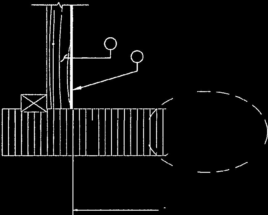
23 USKH Inc. now Stantec Structural Assessment Final Report Coastal Trail Bridges Assessment August 2014 The likely limit state, based on failure analysis of the Westchester North Lagoon Bridge, appears to be cross-grain tension in the glulam beam induced by the ledger connection. The ledger is set inboard of the glulam from 3/4- to 1-inch near the bottom of the glulam beams. The ledger, located near the bottom of the bridge girder, transfers load to only the bottom third of the girder. The load from the deck is then transferred to the stronger upper two thirds of the girder by tension that develops across the grain, i.e. the bottom third has to pull down on the upper two thirds of the beam. The NDS does not recognize this type of loading since wood is extremely weak in cross-grain tension; so designing connections that rely on cross-grain tension is not a recommended practice. In an unrelated part of the code, the NDS gives recommendations for radial tension in curved glulam beams, which is basically the same as cross-grain tension. Using the allowable radial tension stress limitations given in NDS, and an assumption for length influenced by the tire loading, gives a Demand-Capacity Ratio of about 1.4. This means under the assumptions listed, the stress caused by the truck/chipper combination exceeds the allowable stress by about 40 percent. The code has a typical average factor of safety of 2, so assuming new condition with no decay, this connection would probably hold, but it is not recommended. Reference the figures below from American Institute of Timber Construction (AITC) and American Panel Association addressing this type of connection. 1 AITC Typical Construction Details 1 American Institute of Timber Construction (AITC). AITC Typical Construction Details 19

24 USKH Inc. now Stantec Structural Assessment Final Report Coastal Trail Bridges Assessment August Figure 8 Heavy Concentrated Loads Suspended from a Beam 5.2 Sisson Loop Bridge The Sisson Loop Bridge is similar to the 2 nd Avenue Bridge except the original wood decking had been replaced with a greater strength decking and then overlaid with fiberglass decking. The decking was not the load limiting factor so this change neither increases the bridge capacity nor does it help the cross-grain tension problem at the ledger. The additional weight does reduce the allowable uniform live load of the main bridge members down to 67 psf. This is within an acceptable margin of error considering a reduced live load allowed by older codes. Like the 2 nd Avenue Bridge, the limit state is the ledger connection considering cross-grain tension of the glulam girder at the connection interface. The significant moisture and decay present at the interface is alarming and will reduce the connection capacity significantly. 5.3 Fish Creek Bridge The Fish Creek Bridge has a similar configuration to the other bridges but section sizes are different due to the reduced spans. The ledger connection is smaller, and is not inset to the glulam, which greatly limits the ledger strength. The decking called out is smaller than the other bridges, which also reduces decking capacity. The main glulam beams are adequate for the full uniform load or a vehicle similar to the truck/chipper combination. The decking is adequate for the listed design vehicle (7,000 lb street sweeper) but appears deficient for the truck/chipper combination. The limit state for the deck is the ledger connection. The connection is flush mounted with no notch like the 2 nd Avenue or Sisson Loop 2 Form No. EWS T300H 2007 Engineered Wood Systems. 20
25 USKH Inc. now Stantec Structural Assessment Final Report Coastal Trail Bridges Assessment August 2014 bridges so the entire load must be transferred by shear through the lag bolts. The ledger is only a 4x4, which has an actual dimension of 3-1/2 inches. This lag bolt is centered on the ledger, which puts it close to both top and bottom edges. This results in a significant capacity reduction of the connection. This connection limits live load capacity to 51 psf and the ledger is deficient for both vehicle loadings. This connection also results in cross grain tension on the bottom side of the beam, which is not recommended. 5.4 South Lagoon Boardwalk The bridge spans of the boardwalk are of similar configuration and construction to the Fish Creek Bridge. The main beams are adequate for full uniform or vehicle loading, while the decking is limited to a smaller vehicle. The ledger connection limits the overall capacity to 51 psf, and it is deficient with regard to concentrated vehicle loads. The center platform area is framed with dimensional lumber joists bearing on glulams. All the glulams supporting the center platform are adequate for full uniform or vehicle loading. Where the joists span is typically less than 10 feet the area is good for full live load. A section of platform extending from the Harwood Circle entrance to the bridge intersection has a longer joist span (up to 18 feet). This area has a reduced live load of 35 psf. Analysis shows the dimensional lumber cannot support vehicle loading in any location in the platform. 5.5 Possible Temporary Reinforcement It may be possible to temporary reinforce the wood ledger and glulam beams on some bridges to allow trail grooming and other vehicles to pass over those bridges for a short term (1-2 year) timeframe. This would not be a permanent repair but short term reinforcement. The reinforcement would need to directly support the ledger and transfer load around the weakened plane up to competent wood. The reinforcement would involve steel brackets and bolting similar as depicted in Figure 7. A rough order of magnitude cost to install steel brackets on one bridge is about $200,000 - $300,
26
27
28
29 USKH Inc. now Stantec Structural Assessment Final Report Coastal Trail Bridges Assessment August CONCLUSIONS The Coastal Trail Bridge Assessments were directed as a result of the Westchester North Lagoon Bridge failure. That bridge failed under vehicle load. The failure mechanism was cross-grain tension along the plane of the lag bolts attaching the deck support ledger to the main glulam beams. Although this was not a recommended detail, it did not fail until years of water infiltration and decay weakened a plane defined by a line of lag bolts through the ledger. Water draining off the deck onto the ledger below eventually migrated down the lag bolts drilled into the glulams. The constant influx of moisture into the glulam beam kept the plane in a saturated condition and the beam decayed over time. The beams are preservative treated but the treatment only treats the wood on the perimeter and the interior remains vulnerable to decay as moisture is introduced into the center of the beam. The ledger detail relied on cross-grain tension developed in the bottom of the beam to transfer the load. The highly concentrated force from the chipper tire applied a significant shear load across a relatively small area of glulam beam. A local failure developed at one point; then like a zipper, the failure plane spread outward down the beam both sides from the initial point of failure. This bottom side of the beam, ledger, and decking tumbled into the wetland. Since the other Coastal Trail bridges are of similar construction, there are similar issues and concerns. The main ledger lag bolted connection is a conduit for moisture into the main glulam and the connection also induces cross grain tension stress along this plane. Core samples taken from the main girders of the Coastal Trail bridges confirm the glulam beams are saturated to varying degrees. The saturation is inducing decay inside the glulam and weakening a plane similar to the plane of weakness evident in North Lagoon Bridge. Of the bridges examined, the 2 nd Avenue Bridge has the most advanced decay with the core sample being totally saturated and crumbling when withdrawn. The main girders also have significant cracks along the connection plane in various locations. It may be possible to temporary reinforce the wood ledger and glulam beams on some bridges to allow trail grooming and other vehicles to pass over those bridges for a short term (1-2 year) timeframe. This is not a substitute for permanent bridge replacements. Some summary points regarding the bridges site observations, core samples, and analysis: The bridge designs did not consider the cross-grain tension induced by the connection. Normal pedestrian loading will probably not initiate failure until the wood decay is more advanced. The lag bolts are allowing moisture to infiltrate the interior of the glulam beams causing decay and weakness to occur in the connection zone. The beams are preservative treated but the treatments penetrate wood only to a depth of 2 inches. The lag bolts create a path for water to penetrate into the untreated core of the beam. The bridges with the smaller ledger not inset have a significantly reduced capacity and no capacity for vehicle loading. The South Lagoon Boardwalk has a reduced capacity due to the long joist spans. The ledger detail induces cross-grain tension in the main supporting member, which is not recommended in wood design. Vehicles must be kept off the bridges until they are replaced or repaired. A permanent bollard must be installed in front of every bridge access point to prevent vehicles from driving onto the bridges. The bridges, particularly 2 nd Avenue Bridge, should be regularly monitored for signs of failure along the connection zone. A short term reinforcement (1-2 year design life) could be installed for an estimated rough order of magnitude cost of about $200,000 - $300,000 per bridge. 25
30 USKH Inc. now Stantec Structural Assessment Final Report Coastal Trail Bridges Assessment August 2014 A recommended priority of bridge replacements is: 1. 2 nd Ave 2. Fish Creek 3. South Lagoon Boardwalk 4. Sisson 26
31 USKH Inc. now Stantec Structural Assessment Final Report Coastal Trail Bridges Assessment August 2014 This page left intentionally blank 27
32 Appendix A Original Construction Drawings
33
34
35
36
37
38
39
40

41


42
43


44


45
46
47 Appendix B Calculations
48
49
50
51
52
53
54
55
56
57
58
59
60

61
62
63
64
65
66
67
68
69
70
71
72
73
74
75
76
77
78
79
80
81
82
83
84
85
86
87
88
89
90
91
92
93
94
95
96
97