Deep Water Drilled Shafts for the Herrington Lake Bridge Replacement Project
|
|
|
- Erika Hicks
- 5 years ago
- Views:
Transcription


1 Deep Water Drilled Shafts for the Herrington Lake Bridge Replacement Project Darrin Beckett, P.E. Kentucky Transportation Cabinet 49 th Southeastern Transportation Geotechnical Engineering Conference October 8-11, 2018 Louisville, Kentucky Rev. 10/04/2018
, Thermal Integrity Profiling (TIP) Shaft")
2 Presentation Overview Herrington Lake & Original Bridge Project Overview Pier 1 Features Including Geotech Conditions & Considerations Barge Anchoring System & Ground Preparation Casing Lowering Sequence Drilling Methods & Equipment Drilled Shaft Testing & Cavity Stabilization Video Inspection, Sonar Calipering Crosshole Sonic Logging (CSL), Thermal Integrity Profiling (TIP) Shaft Reinforcement Cage Assembly 2018 Herrington Lake Water Levels #1-2:00


3 Project Site Herrington Lake (About 75 Miles Southeast of Louisville) #2-2:30
. Deepest lake in Kentucky Max. Depth 249 ft.; Avg. 78 ft.")
4 Herrington Lake Created in 1920 s when a dam on the Dix River was constructed to generate hydro-electric power and for flood mitigation. Dix Dam was the largest rock fill dam in the world when constructed. Herrington Lake & Dix Dam are owned by Kentucky Utilities (KU). Deepest lake in Kentucky Max. Depth 249 ft.; Avg. 78 ft. Approximately 35 miles long & up to about 1200 ft. wide Reference: Herrington Lake Conservation League ( #3-3:00

5 Herrington Lake E. W. Brown Generating Station Hydro Electric Coal Solar Dix Dam Contractor s Staging Area & Lake Access About Three River Miles KY 152 Bridge Site #4-3:30

6 Project Site in October 2017 Original Bridge New Bridge Alignment Built in 1920 s before lake was impounded. Closed for repairs several times in recent years and had posted weight limits. Weight limit lowered to 3 tons in January 2018 and permanently closed in March 2018 due to the need for a new deck. ( 25 mile detour) 10/09/2017 #5 4:00

7 Project Overview $30M Construction Contract Three Span Bridge (350, 350, ) Incidental Roadway Work Remove Existing Structure #6-4:30


8 Major Project Team Organizations Owner Design Consultant Geotechnical Consultant General & Drilled Shaft Contractor Construction Engineering Consultant Drilled Shaft Testing Consultants Concrete Supplier #7-5:00
9 Presentation Focuses on Four Shafts at Pier 1 ( $10M or about 1/3 of contract) water 185 ft. summer pool 180 ft. tall 8.5 ft. dia. cased sections 60 ft. 60 ft. water 170 ft. winter pool upper & lower 3 ft. thick concrete intermediate braces for stiffness at approx. 1/3 points 40 ft. long 8.0 ft. dia. rock sockets 60 ft. Technique Shaft was considered but deemed too expensive 15 ft. long 8.0 ft. dia. design rock sockets #8 6:00
10 Pier 1 Geotechnical Conditions & Considerations At each of the four shafts, one exploration boring w/ 90 to 100 ft. of rock core < 10 ft. of Overburden Bedrock consists of Dolomitic Limestone with Interbedded Shale Average Unconfined Compressive Strength 19,000 psi Voids & highly fractured zones down to Elev. 523 ft. ( 20 to 25 ft. into bedrock) Cavity Stabilization set up in contract due to encountered voids Bedrock above Elev. 523 ft. neglected for design Below Elev. 523 ft. Rock Quality Designation (RQD) generally > 80 End Bearing neglected for axial resistance evaluation 40 ft. long 8.0 ft. diameter rock sockets with 15 ft. long design rock sockets #9-7:00
11 Pier 1 Specified Construction Tolerances At the top of the shaft - within 6 inches of plan position At the top of the rock socket - within 6 inches of plan position Vertical alignment of the rock sockets - within ¼ inch per foot IS THIS EVEN POSSIBLE??? FOUR BIDS!!! (ranging from $30M to $47M) Construction tolerances intentionally set tighter than design tolerances Potential for adjusting superstructure if substructure unit was within plumb but slightly out of location #10-8:00
12 Barge Anchoring System & Ground Prep anchors drilled into rock cliffs * Contractor s Means & Methods Plan View anchor cables (min. 20 ft. below water) * Contractor s Means & Methods Elevation View clamshelled overburden & chiseled bedrock to relatively level surface at approx. Elev. 546 ft. (verified using sonar) #11-9:00

13 Casing Assembly and Lowering Sequence Lower Intermediate Concrete Brace Constructed Above Water Strand Jack Cables for Lowering 60 ft. of Casings Below Brace * Contractor s Means & Methods 11/10/2017 #12-9:30

14 Casing Assembly and Lowering Sequence Lower Intermediate Concrete Brace Constructed Above Water 60 ft. of Casings Spliced Above Brace 60 ft. of Casings Below Brace 11/29/2017 * Contractor s Means & Methods #13-10:00

15 Casing Assembly and Lowering Sequence Upper Intermediate Concrete Brace 12/13/2017 * Contractor s Means & Methods #14-10:30

16 Casing Assembly and Lowering Sequence Upper Intermediate Concrete Brace 60 ft. of Casings Spliced Above Brace * Contractor s Means & Methods 12/19/2017 #15-11:00
17 Casing Assembly and Lowering Sequence poured 5 ft. thick tremie seal & lowered casings to bedrock surface through plastic concrete touched down casings onto rock surface & lifted back up a few feet relatively level rock surface * Contractor s Means & Methods #16-12:00


18 The BUMA! BUMA 3030 Casing Mounted Reverse Circulation Drill 250 ft. Above Shaft Tip Elev. Manufactured in South Korea specifically for this project. 04/30/2018 #17-12:30

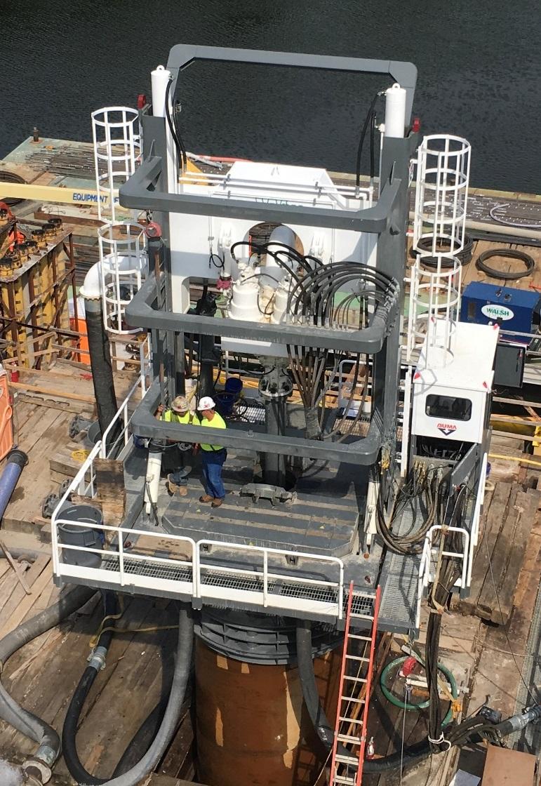

19 The BUMA Up Close 05/15/ /29/2018 #18-13:00

20 Reverse Circulation Rock Roller Bit 06/14/2018 #19-13:30

21 Video Inspection of Rock Socket (Shaft #6) Weighted Tape Along Sidewall Contract documents required flocculent to be used per the manufacturer s recommendations to increase visibility. Contractor reported that they used flocculent in accordance with the manufacturer s recommendations and allowed the hole to flocculate for several hours. Although we believed that additional floc time may have provided more visibility we agreed to abandon efforts to perform the video inspections. #20 14:30


22 Typical Sonar Calipering Images Showing Karst Features (Shaft #5 Rock Socket) Approximate Bottom of Casing Karst features measured up to about 18 inches beyond nominal socket wall Cavity Stabilization Method: Pour Cavity Stabilization Concrete in Rock Socket & Re-Drill Socket Elev. 523 ft. 40 ft. Rock Socket 15 ft. Design Socket #21-15:30


23 Shaft #5 Socket After Cavity Stabilization and Redrilling #22-16:00
24 Sonar Caliper Verticality Plots - Center of Shaft #6 Longitudinal Direction Transverse Direction 0.1 ft. 0.4 ft ft. Tolerance Plan Position ft. Tolerance Exaggerated Scale - graphs about 200 ft. tall by 3 ft. wide ft. Tolerance Plan Position 10.0 ft. Left ft. Tolerance 0.3 ft. 0.3 ft in./ ft. < 0.25 in./ft in./ ft. < 0.25 in./ft. #23-17:00
25 Evaluation of Shafts Relative to Specified Tolerances Shaft No. (In Order of Construction) Vector Total Horizontal Distance from Plan Position at Top of Shaft (ft.) Vector Total Horizontal Distance from Plan Position at Top of Rock Socket (ft.) Rock Socket Slope (in./ft.) Tolerance * * Due to unresolved questions about the sonar calipering results, it is not clear if Shaft No. 4 was really this far outside of the specified tolerance. The shaft is still within applicable design tolerance. #24-18:00
26 Some Recommendations for Sonar Calipering Specifications Clearly state what specific data & information are needed. Require the reference elevation (zero depth) and location of sonar device and/or casing to be surveyed in conjunction with every test such that the sonar test coordinates in the hole can be tied to elevation and project station & offset. Require the sonar test to be oriented relative to the ahead station direction. Require preliminary data reports with verticality analysis within 12 hours after testing and final report within one week. Require example verticality analysis in accordance with specified requirements to be submitted for qualification to perform testing on the project. Require dry run test and submittal ASAP and prior to completing first excavation and pay for this as a regular test. Include clear language to require responses to ed questions and/or review comments in a timely manner. #25-19:00
27 Shaft No. First Test Second Test (In Order of Construction) Concrete Age (Days) No. of Flaws / No. of Defects Concrete Age (Days) No. of Flaws / No. of Defects / / /8 40 1/ /2 N/A N/A /6 N/A N/A Flaws and Defects criteria defined in contract documents based on wave speed and energy. 8.5 ft. Diameter Cased Sections, 8.0 ft. Diameter Rock Sockets 8 tubes with 28 tested tube pairs Crosshole Sonic Logging (CSL) Shaft 5 was accepted based on improvement seen in Shafts 4 & 6 and by considering CSL data in conjunction with Thermal Integrity Profiling (TIP) data, concrete cylinder breaks and contractor s quality protocols. About 30 days minimum was approximate optimal age for CSL testing these shafts, apparently due to large diameters and the specific concrete mix. #26-20:00


28 Thermal Integrity Profiling (TIP) Data - Shaft 7 Specifications required obtaining water temperature data. In transition zones, CSL data more reliable to evaluate shaft integrity. Embedded wires were specified & used; we generally prefer this method. Embedded wires require responsible contractor personnel to retrieve data. Should transmit data electronically to testing consultant and/or have capability to backup data. intermediate braces rock socket concrete temp generally parallels water temp. plot water temperature variation 48 o to 80 o F #27-21:00


29 Shaft Reinforcement Cage Assembly cages assembled in two sections in the vertical position the two sections were spliced over the hole 7 ft. nominal * Contractor s Means & Methods 05/01/ /13/2018 #28-21:30

30 2018 Herrington Lake Water Levels Approx. Summer Pool = Elev. 738 ft. > 30 ft. Variation Approx. Winter Pool = Elev. 725 ft. Tremie Seal Pour 03/16/18 - Shaft #5 Pour 06/07/18 #29-22:00

31 10/04/2018 Thank You
32