CONSTRUCTION SPECIFICATION MANUAL TECHNICAL STANDARDS FOR WATER DISTRIBUTION SYSTEM. Tavares, Florida
|
|
|
- Valentine Knight
- 5 years ago
- Views:
Transcription

1 CONSTRUCTION SPECIFICATION MANUAL TECHNICAL STANDARDS FOR WATER DISTRIBUTION SYSTEM Tavares, Florida Jones Edmunds & Associates, Inc. Project No
2 CONSTRUCTION SPECIFICATION MANUAL TECHNICAL STANDARDS FOR WATER DISTRIBUTION SYSTEM Section 2 Surface Restoration Section 15 Utility/Water General Section 16 Water Distribution System TABLE OF CONTENTS Section 17 Disinfection of Domestic Water Piping Section 18 Horizontal Directional Drilling Section 19 Pipe, Fittings, Valves, and Appurtenances Standard Details W-1 Service Connection Details Single Family W-2 Trenching and Bedding Details W-3 Gate Valve and Box Detail W-3A Valve Collar Detail W-4 Service Connection Details Condos W-5 Locating Wire Splicing W-6 Temporary Jumper Connection Detail W-6A Temporary Jumper Connection Notes W-7 Thrust Restraint Details W-8 Utility Separation Details W-9 Utility Pipe Location Materials W-9A Tracer Wire Box W-10 Utility Pipe Location Material W-11A General Water Notes W-11B General Water Notes W-11C General Water Notes W-12 Detector Check Valve Assembly W-13 Offset Air Release Valve Vault Detail W-14 Typical Water Service and Hydrant Location Detail W-15 Fire Hydrant Reflector Detail W-16 Blowoff Valve Detail i TABLE OF CONTENTS
3 Standard Details (continued) W-17 Wet Tap Sleeve and Tapping Valve W-18 Fire Hydrant with Valve W-19 Single Plastic Meter Box Detail W-20 Jumbo Plastic Meter Box Detail W-21A Single Concrete Meter Box Detail W-21B Single Concrete Meter Box Detail W-22A Jumbo Concrete Meter Box Detail W-22B Jumbo Concrete Meter Box Detail W-23 Pressure Backflow Preventer with Water Meter Detail ii TABLE OF CONTENTS
4 SECTION 2 SURFACE RESTORATION PART 1 GENERAL 1.01 SCOPE OF WORK A. This Section covers the work necessary to provide for the restoration of all asphalt and concrete pavement and concrete sidewalks removed during construction SUBMITTALS The Contractor shall submit shop drawings in accordance with Section 1 General Provisions: A. Limerock material submittal is to be made to include liquid limit, plastic index, gradation, certification regarding deleterious material, limerock bearing ratio (LBR), Florida Department of Transportation (FDOT) pit number, and other information as required to indicate performance in accordance with the specifications. B. Information regarding asphaltic and Portland cement concrete materials and mix shall be submitted as required by the referenced FDOT specifications REFERENCE STANDARDS Reference standards and recommended practices referred to in this Specification Section shall be the latest revision of any such document in effect at the bid time. The following documents are a part of this Section. Where this Section differs from these documents, the requirements of this Section shall apply. A. The latest edition of the FDOT Standard Specifications for Road and Bridge Construction (Standard Specifications) and Roadway and Traffic Design Standards shall be referred to for construction, workmanship, and quality control as specified with exceptions as noted in this Section. 1. Where the referenced FDOT Specifications cite "the Department," this shall be modified to the Owner and/or Utility Director or his Designee by this contract. 2. The Contractor shall retain an independent testing agency, as approved by the Utility Director, to perform all tests, including tests referenced to be performed by the Utility Director SURFACE RESTORATION MAY 2010
5 B. American Society of Testing and Materials (ASTM) 1. ASTM D1556 Standard Test Method for Density and Unit Weight of Soil in Place by the Sand-Cone Method. 2. ASTM D1557 Standard Test Methods for Laboratory Compaction Characteristics of Soil Using Modified Effort (56,000 ft-lbf/ft 3 (2,700 knm/m 3 )). 3. ASTM D2167 Standard Test Method for Density and Unit Weight of Soil in Place by the Rubber Balloon Method. 4. ASTM D6938 Standard Test Method for In-Place Density and Water Content of Soil and Soil-Aggregate by Nuclear Methods (Shallow Depth) QUALITY ASSURANCE A. The Contractor shall perform field-density tests along the centerline of construction or as directed by the Utility Director or his Designee and in accordance with the FDOT s Standard Specifications for Road and Bridge Construction, latest edition. B. The Contractor shall field check the depth of stabilization and/or limerock at each road crossing with a pipeline. C. The City may require additional testing as deemed necessary. The Utility Director or his Designee shall interpret test results and the Contractor shall perform remedial work as directed by the City. D. Laboratory maximum dry density of soil mixtures at optimum moisture shall be determined by ASTM D1557 for subgrade, stabilized subgrade, and limerock base course. E. Field density of stabilized subgrade and soils or soil mixtures in fill or backfill shall be determined by ASTM D2167, D1556, or Nuclear Method D2922 or ASTM D1556 or D2922 for limerock base course. F. Bearing value of stabilized subgrade shall be determined by the methods required for determining limerock bearing ratio (LBR) according to the FDOT, Standard Specification FM G. Field density of stabilized subbase shall be 98% or greater of the Modified Proctor maximum dry density, ASTM D1557. H. The Utility Director or his Designee shall have sole responsibility for interpreting all test results. The Contractor shall bear the cost of all retests due to failure to achieve specified requirements SURFACE RESTORATION MAY 2010
6 1.05 WARRANTIES A. Warranties shall be in accordance with Section 23 Warranty. PART 2 PAVEMENT PRODUCTS 2.01 ROCK BASE A. The following sections of FDOT Standard Specifications shall apply: 2.02 STABILIZING 1. Section 200-1, Description. 2. Section 200-2, Materials A. The following sections of FDOT Standard Specifications shall apply: 1. Section 160-1, Description 2. Section 160-2, Stabilized Subgrade, Type B 3. Section 160-4, Materials 2.03 PRIME AND TACK COATS FOR BASE COURSES A. The following sections of FDOT Standard Specifications shall apply: 1. Section 300-1, Description 2. Section 300-2, Materials 3. Section 300-3, Equipment 2.04 SUPERPAVE ASPHALT A. The following sections of FDOT Standard Specifications shall apply: 1. Section 334-1, Description 2. Section 334-2, Materials 3. Section 334-3, General Composition of Mixture 4. Section 334-4, Acceptance of the Mixture at the Plant 5. Section 334-5, Acceptance of the Mixture on the Roadway SURFACE RESTORATION MAY 2010
7 2.05 CEMENT CONCRETE PAVEMENT A. The following sections of FDOT Standard Specifications shall apply: 1. Section 350-1, Description 2. Section 350-2, Materials 2.06 TRAFFIC STRIPES AND MARKINGS A. The following sections of FDOT Standard Specifications shall apply: 1. Section 711-1, Description 2. Section 711-2, Materials PART 2A CONCRETE SIDEWALK PRODUCTS 2.01A MATERIALS A. The following sections of FDOT Standard Specifications shall apply: 2.01B FORMS 1. Section 347, Concrete 2. Section 415, Reinforcement 3. Section 932, Joint Materials A. The following sections of FDOT Standard Specifications shall apply: 1. Section 520-3, Form Materials 2.01C EXCAVATION AND COMPACTION A. The following sections of FDOT Standard Specifications shall apply: 2.01D JOINTS 1. Section 520-4, Excavation 2. Section 120-9, Compaction A. The following sections of FDOT Standard Specifications shall apply: 1. Section , Contraction Joints 2. Section , Expansion Joints SURFACE RESTORATION MAY 2010
8 2.01E FINISHING A. The following sections of FDOT Standard Specifications shall apply: 1. Section 520-7, Finishing 2.01F CURING A. The following sections of FDOT Standard Specifications shall apply: 1. Section 520-8, Curing PART 3 EXECUTION 3.01 EXCAVATION AND EMBANKMENT A. The following sections of FDOT Standard Specifications shall apply: 1. Section 120-1, Description 2. Section 120-2, Classifications of Excavation 3. Section 120-3, Preliminary Soils Investigation 4. Section 120-4, Removal of Unsuitable Materials and Existing Roads 5. Section 120-5, Disposal of Surplus and Unsuitable Material 6. Section , Materials for Borrow 7. Section 120-7, Materials for Embankment 8. Section 120-8, Embankment Construction 9. Section 120-9, Compaction Requirements 10. Section , Acceptance Program 11. Section , Maintenance and Protection of Work 12. Section , Construction B. Exceptions 1. Section , Subsoil Excavation: Unsuitable soils shall be those in Classifications A-6, A-7, or A-8 in the American Association of State Highway and Transportation Officials (AASHTO) System. 2. Section , Removal of Existing Old Road: Where removal of existing pavement is called for, it shall be removed to the full depth as indicated in the cross-sections and replaced with new limerock and paving. 3. Section , Disposal of Paving Materials: Disposing of muck on side slopes shall not apply SURFACE RESTORATION MAY 2010
9 4. Section , General: Laboratory maximum dry density shall be determined by Modified Proctor, ASTM D1557. Field densities shall be determined by ASTM D2167, D1556 or Nuclear Method D2922. All embankments shall be compacted to not less than 95% of the maximum dry density, as determined by modified Proctor, ASTM D Section , Construction Tolerances: No tolerance greater than 0.1- foot above or below the plan cross-section will be allowed ROADWAY STABILIZING A. The following sections of FDOT Standard Specifications shall apply: 1. Section 160-1, Description 2. Section 160-2, Stabilized Subgrade 3. Section 160-3, Stabilized Subbase 4. Section 160-4, Materials 5. Section 160-5, Construction Methods 6. Section 160-6, Stabilized Subbase (Additional Strengthening of Upper Portion) 7. Section 160-7, Acceptance Program 8. Section 160-8, Density Requirements B. Exceptions 1. The Contractor shall stabilize the road bed to a minimum depth of 12 inches as shown on the Drawings. 2. Section , Undertolerance in Bearing Value Requirements: no undertolerance will be acceptable LIMEROCK BEARING RATIO AND DENSITIES A. Stabilized finish grade and stabilized shoulders shall have a minimum Limerock Bearing Ration (LBR) value of 40. B. Field density of stabilized finished grade shall be a minimum of 98% of the Modified Proctor maximum dry density as specified in ASTM D1557 to a minimum depth of 12 inches as shown on the Drawings PRIME AND TACK COATS A. The following sections of FDOT Standard Specifications shall apply: SURFACE RESTORATION MAY 2010
10 3.05 LIMEROCK BASE 1. Section 300-3, Equipment 2. Section 300-5, Cleaning Base and Protection of Adjacent Work 3. Section 300-6, Weather Limitations 4. Section 300-7, Application of Prime Coat 5. Section 300-8, Application of Tack Coat A. The following sections of FDOT Standard Specifications shall apply: 1. Section 200-3, Equipment 2. Section 200-4, Transporting Limerock 3. Section 200-5, Spreading Limerock 4. Section 200-6, Compacting and Finishing Base 5. Section 200-7, Acceptance Program 6. Section 200-8, Priming and Maintaining B. Exceptions 1. Section , Density: The minimum density which will be acceptable for paved areas will be 98% of the maximum dry density as determined by Modified Proctor, ASTM D Section , Depth and Surface Testing Requirements: Thickness of base shall be measured at intervals not to exceed 200 feet SUPERPAVE ASPHALT A. The following sections of FDOT Standard Specifications shall apply: 1. Section 320-5, Paving Equipment 2. Section 330-1, Description 3. Section 330-2, Quality Control by Contractor 4. Section 330-3, Limitations of Operations 5. Section 330-4, Preparation of Asphalt Cement 6. Section 330-5, Preparation of Aggregates 7. Section 330-6, Preparation of the Mixture 8. Section 330-7, Transportation of the Mixture 9. Section 330-8, Preparation of the Application Surfaces 10. Section 330-9, Placing Mixture 11. Section , Compacting Mixture 12. Section , Joints 13. Section , Surface Requirements SURFACE RESTORATION MAY 2010
11 14. Section , Protection of Finished Surface 15. Section 334-3, General Composition of Mixture 16. Section 334-4, Acceptance of Mixture 3.07 CEMENT CONCRETE PAVEMENTS A. The following sections of FDOT Standard Specifications shall apply: 1. Section 350-1, Description 2. Section 350-2, Materials 3. Section 350-3, Equipment 4. Section 350-4, Subgrade Preparation 5. Section 350-5, Setting Forms 6. Section 350-6, Protection from Weather 7. Section 350-7, Placement of Reinforcement 8. Section 350-8, Placing Concrete 9. Section , Final Finish 10. Section , Curing 11. Section , Surface Requirements 12. Section , Joints 13. Section , Thickness Determinations 3.08 PAVEMENT REPAIR A. At his own expense the Contractor shall repair all damage to pavement as a result of work under any Contract in a manner satisfactory to the Utility Director or Public Works Director. Pavement shall be saw cut and repaired to match the original surface material and original grade. However, the asphalt concrete thickness shall not be less than 2 inches. The repair shall include preparing the subgrade, placing and compacting the applicable base, priming the limerock base, and placing and maintaining the surface treatment as specified in this Section. B. The width of all repairs shall extend at least 12 inches beyond the limit of the damage. The edge of the pavement to be left in place shall be cut to a true edge with a saw or other approved method so as to provide a clean edge to abut the repair. The line of the repair shall be reasonably uniform with no unnecessary irregularities JOINTS A. General pavement joints within asphalt or concrete driveways and roadways and where specified or directed by the Utility Director, shall be mechanically sawed butt joints. The edges of asphalt pavement shall be trimmed to straight lines which a roller can follow or formed SURFACE RESTORATION MAY 2010
12 3.10 TRAFFIC STRIPES AND MARKINGS A. The following sections of FDOT Standard Specifications shall apply: 1. Section 711-1, Description 2. Section 711-2, Material 3. Section 711-3, Equipment 4. Section 711-4, Application 5. Section 711-5, Contractor s Responsibility for Notification 6. Section 711-6, Protection of Newly Applied Traffic Stripes and Markings 7. Section 711-7, Method of Measurement 8. Section 711-8, Basis of Payment 3.11 CONCRETE SIDEWALK A. The following sections of FDOT Standard Specifications shall apply: 1. Section 522-1, Description 2. Section 522-2, Material 3. Section 522-3, Forms 4. Section 522-4, Foundation 5. Section 522-5, Joints 6. Section 522-6, Placing Concrete 7. Section 522-7, Finishing 8. Section 522-8, Curing 9. Section 522-9, Method of Measurement 10. Section , Basis of Payment 3.12 CONCRETE SIDEWALK REPAIR A. At his own expense the Contractor shall repair all damage to concrete sidewalks as result of his work in a manner satisfactory to the Utility Director or Public Works Director. Sidewalks shall be saw cut and repaired to match the original width, thickness and original grade. However, the concrete thickness shall not be less than 4 inches. The repair shall include preparing the subgrade, placing of forms, placing concrete, finishing and curing as specified in this Section. B. The width of all concrete sidewalk repairs shall extend at least 12 inches beyond the limit of the damage. The edge of the sidewalk to be left in place shall be cut to a true edge with a saw or other approved method so as to provide a clean edge to abut the repair. The line of the repair shall be reasonably uniform with no unnecessary irregularities SURFACE RESTORATION MAY 2010
13 3.13 FOUNDATION A. Compact fill areas, including cut areas under sidewalk that have been excavated more than 6 inches below the bottom of the sidewalk, to a minimum of 95% of AASHTO T 99 density. The area to be compacted is defined as that area directly under the sidewalk and 1 foot beyond each side of the sidewalk when right-ofway allows JOINTS A. Form ½ expansion joints between the sidewalk and the curb or driveway or at fixed objects and sidewalk intersections with a preformed joint filler meeting the requirements specified in FDOT Section B. The contractor may use open type or sawed contraction joints. Form open type contraction joints by staking a metal bulkhead in place and depositing the concrete on both sides. After the concrete has set sufficiently to preserve the width and shape of the joint, remove the bulkhead. After finishing the sidewalk over the joint, edge the slot with a tool having a ½ inch radius FINISHING If electing to saw the contraction joints, cut a slot approximately 3/16 inch wide and not less than 1 ½ inches deep with a concrete saw after the concrete has set, and within the following periods of time: Joints at not more than 30 foot intervals Within 12 hours after finishing Remaining joints Within 96 hours after finishing A. Screeding: Strike off the concrete by means of a wood or metal screed, used perpendicular to the forms, to obtain the required grade and remove surplus water and laitance. Surface Requirements: Provide the concrete with a broom finish. Ensure that the surface variations are not more than ¼ inch under a 10 foot straightedge, or more than 1/8 inch on a 5 foot transverse section. Finish the edge of the sidewalk with an edging tool having a radius of ½ inch. END OF SECTION SURFACE RESTORATION MAY 2010
14 SECTION 15 UTILITY/WATER GENERAL 1.01 AUTHORITY A. Approval 1. These design standards are accepted and approved by the Tavares City Council. B. Scope and Intent 1. It is intended for these Development Procedures to establish minimum engineering requirements for projects submitted to the City. The development procedures will apply to all development and construction projects, both public and private, within the jurisdiction of the City of Tavares. C. Variances 1. Under extreme conditions with specific applications, the following procedures and policies may be altered to meet certain conditions that are beyond the control of the developer and provided such deviations or alterations are acceptable to the City. Final decisions concerning such alterations shall be made by the Utility Director or his Designee. D. Changes to These Standards 1.02 PLANS 1. Changes to these standards may be made by the Utility Director as deemed necessary to improve/maintain the integrity of the City utility systems. 2. A pre-design conference between the owner, his engineer and the City shall be required to be held prior to submittal of construction plans. A. Submission 1. Prior to installation of any water distribution system, a hydraulic model of the water system shall be performed by a Professional Engineers registered in the State of Florida. The modeling software used shall be WaterGEMS or other software approved by the Utility Director or his Designee. The modeling results shall be submitted to the Utility Director UTILITY/WATER-GENERAL MAY 2010
15 for approval prior to installation of any water distribution system. The Utility Director shall establish minimum flow, pressure criteria, and fire flow to be used for modeling purposes. 2. Plans shall be valid for construction for a period of one year from the date of City approval. All items not under construction within one year of the approval date shall require resubmittal and new approval prior to the commencement off construction. 3. All construction plans and specifications submitted to the City for review and approval shall bear the seal and signature of the Florida Registered Professional Engineer responsible for the project. The address and telephone number of this person shall be shown along with the signature. 4. Four (4) sets of signed and sealed plans and specifications shall be submitted for approval to the City. Two approved sets shall be returned to the Engineer for the construction of the project. 5. A site plan shall be provided to indicate proposed development property boundaries and sub-divided property/lot lines and to include water layout. Tie in to the existing water system to include proposed existing main line. The site plan shall include; existing and proposed water lines, size of pipe, valves, and services stub outs for each lot, backflow device (s), air relief valves, etc. 6. All systems shall be designed to install all Water Meters on the Rights-of- Way Only. Encroachment of meter box and meter on private property shall be strictly prohibited. 7. All construction drawings must be prepared in AutoCAD format. The version of AutoCAD used shall be compatible with the current version in use by the City. No other CAD software shall be used in preparation of construction drawings unless authorized in writing by the Utility Director, or his Designee. B. Assembly 1. Sheet Size a. The standard size sheet for construction plans submitted to the City for approval shall be 24" X 36". Worksheets and data sheets used in preliminary design work and reviews are not limited to any size, except that which is convenient to handle UTILITY/WATER-GENERAL MAY 2010
16 1.03 CONSTRUCTION A. Start 2. Items of Construction Required a. The developer shall provide as appropriate water, sanitary sewers, reuse systems, roadways and stormwater management areas, and all other necessary improvements in accordance with City specifications, standards and policies. 3. Utility Coordination a. It shall be up to the developer to coordinate all utilities within his development. 4. City Standards and Specifications a. Copies of City standards and specifications may be obtained from the Utilities Department or online at 1. Notification a. The City shall be notified in writing of the proposed date of the beginning of construction of the water facilities. Any time that work is to stop for a period of time in excess of two (2) working days, the City shall be notified of such interruption. Note: Material shop drawings must be furnished to the Utility Director or his Designee, reviewed and approved by the Utility Director or his Designee, before work may begin on on the approved project. 2. Pre-Construction Conference a. A pre-construction conference shall be held at least two (2) days before the commencement of construction. The developer shall be responsible for arranging this conference with the City. The conference should include the contractor, City Staff as well as other utilities servicing the project. 3. Required insurance certificates shall be provided by the developer to the City when work involves City property, Right-of-Way, or easements UTILITY/WATER-GENERAL MAY 2010
17 B. Completion 1.04 INSPECTION Work shall not begin until such certificates are provided. The surety shall have an A.M. Best Financial Performance rating of no less than A-. Contractor will cause the Bonds to be recorded with the Clerk of the Circuit Court in Lake County. Failure of the Contractor to deliver required Bonds in the form prescribed may constitute an event justifying termination of construction for cause. The expense for all Bonds shall be Contractor s responsibility. 1. As-Built Drawings a. Within two weeks following final inspection, the developer shall submit Record Drawings in accordance with requirements of Final Acceptance as shown below. 2. Certificates of Compliance a. Certificates of compliance with the specifications furnished by the material supplier shall-be submitted on all materials used in the completion of this work. 3. Off-Site Pollution Protection A. Periodic a. It shall be the developer's sole responsibility to provide erosion and sedimentation control measures during construction in accordance with requirements of the St. John s River Water Management District, Florida Department of Environmental Protection and other regulatory agencies having jurisdiction. In the event such protection is inadequate, it will be the developer's responsibility to immediately take measures to bring the project into full compliance with required erosion and sedimentation controls. 1. The City will periodically visit the project site to make a visual inspection of the progress of the work and methods of construction. Upon observation of work not done in accordance with the plans and specifications, the City will notify the developer's contractor, and request that necessary corrections be made or tests be performed to assure compliance with the specifications, at no cost to the City UTILITY/WATER-GENERAL MAY 2010
18 B. Final 2. All projects shall be subject to inspection during and upon completion of construction by an authorized representative of the City. Presence or absence of a City inspector during construction does not relieve the Developer and/or Contractor from adherence to the approved plans and specifications. 3. The work shall at all times be subject to inspection by authorized representatives of the City, and materials and/or workmanship found not meeting the requirements of approved plans and specifications shall be immediately brought into conformance with said plans and specifications. 4. An authorized representative of the City shall make final inspection of the project after completion to determine acceptability of the work. Before this final inspection can be made, the Developer/Contractor shall notify the City in writing that the work has been completed in accordance with the approved plans and specifications. Any existing City utilities damaged during the project will be repaired by Developer/Contractor at their own expense. 1. The City shall be notified in writing when the project is complete. Upon receiving a written request for final inspection of the completed work, the representatives of the City, together with the representatives of other interested agencies, shall perform the final inspection within two weeks of the receipt of the request. C. Changes 1. All field changes to previously approved construction plans shall be in accordance with these specifications and approved by the Utility Director, or his Designee, prior to implementation FINAL ACCEPTANCE Note: All changes will be corrected on the Approved final AS-BUILT- DRAWINGS before submitting to FDEP for clearance and City final acceptance and approval. A. When facilities qualify as public facilities, the City will accept ownership of the completed facilities when the work has passed the final inspection, proper acquisition documents are completed, acceptable Record Drawings are submitted to the City, and Clearance and Certification of Completion has been received UTILITY/WATER-GENERAL MAY 2010
19 from FDEP. The Record Drawings shall be completed by the Engineer of Record for the project and shall show final locations of valves, fittings, water mains, air release valves, and all other pertinent information related to the utility system. Water service line location and measurements shall be located at the end of the service from two property corners with the letter W indicating water service (s) and V indicating valve (s) etched in the curbing and painted blue. B. Final acceptance by the City will be made in writing upon satisfactory completion of the project, including final inspection and submittal of the following documents: 1. One (1) Mylar set of Record Drawings signed and sealed by a Florida Registered Professional Land Surveyor. 2. Three (3) Print sets of Record Drawings signed and sealed by a Florida Registered Professional Land Surveyor. 3. One (1) CD or DVD containing the Record Drawings, in the AutoCAD format in current use by the City. No other CAD software shall be allowed unless previously approved in writing by the Utility Director or his Designee. The CD/DVD shall be labeled as follows: a. Project Name b. Developer and Contractor Name c. Date of Record Drawings included on disc. 4. Certifications of Completion from all Regulatory Agencies (i.e., Florida Department of Environmental Protection, St. Johns River Water Management District, Florida Department of Transportation, etc.). 5. Recorded easement documents. 6. Maintenance Bond in the amount of 10% or all contributed assets, with a duration of 2 years. Maintenance Bond to be accompanied by a letter prepared by the Engineer of Record documenting the Bond amount. 7. Copies of all approved Testing Results (i.e., Pressure Test, Mandrel, Densities/Compaction, etc.). 8. Copies of approved Bacteriological Sampling on water lines. C. Final acceptance by the City will be made in writing upon satisfactory completion of the project, including all items above. The Developer/Contractor shall UTILITY/WATER-GENERAL MAY 2010
20 1.06 MAINTENANCE warranty the work for a period of one year from the date of final acceptance and shall immediately correct any deficiencies in the work due to materials and/or workmanship, which occur during the warranty period. The date of final acceptance shall be the date on which the Developer/Contractor has fulfilled all conditions necessary for final acceptance and has received notification in writing of final acceptance by the City. A. All items or systems must be designed in such a manner to minimize future maintenance. A one-year warranty on all work shall be furnished to the City at the time of final acceptance, along with all warranties and manufacturers' manuals for all items to be maintained by the City. Warranties shall be extended by six months from the date of any repair to warranted items. All disturbed earthen areas shall be sodded prior to acceptance TRANSFER OF PRIVATE OWNERSHIP A. When transfer of private facilities to public ownership takes place, all such private facilities shall be brought up to the current City standards at no cost to the City, insofar as construction and maintenance are concerned, before the City will accept such facilities. The City shall be furnished copies of all approvals; permits, certificates of completion, etc., to or from completion, etc., to or from other agencies such as Lake County, Florida Department of Environmental Protection, St. Johns River Water Management District, Florida Department of Transportation, railroads, etc., before proceeding with the transfer. B. Proof of satisfactory completion of water facilities, positive water bacteriological tests, and submission of quit claim deeds, bills of sale, prior and current permits, warranties, manufacturer s manuals, and a two year maintenance bond shall be furnished to the City prior to acceptance PROPERTY OWNERSHIP A. All facilities to be owned or maintained by the City shall be located on City property, within City right-of-way or on easements dedicated to the City for the uses intended. All city meters will be installed only within the City right-of-way TESTING A. It shall be the Contractor s responsibility to provide the necessary equipment and personnel for all inspections and testing. This shall include all safety equipment necessary to meet OSHA requirements. Inspections will be cancelled if proper UTILITY/WATER-GENERAL MAY 2010
21 testing or safety equipment is not on site and readily available at the time of the inspection. B. All testing shall be witnessed by the Utility Director or his Designee. C. Access to work areas shall be provided by the Contractor for all required inspections. In cases where the Contractor has proceeded with work which the City had requested to inspect or witness without said requested inspection, the Contractor shall bear all costs associated with uncovering, retesting, additional testing, or any other means necessary to provide physical evidence as to the acceptability of the work performed by the Contractor. Such costs shall be the responsibility of the Contractor regardless of whether or not the work is found to be defective or acceptable to the City. END OF SECTION UTILITY/WATER-GENERAL MAY 2010
22 SECTION 16 WATER DISTRIBUTION SYSTEM 1.01 SCOPE A. This section includes general technical criteria for the design and installation of water distribution systems for potable water service. The relevant provisions of other sections of this specification shall be applicable to this section unless otherwise indicated herein or approved by the Utility Director or his designee. B. The Contractor shall provide all work necessary for the construction and testing of a complete potable water piping system. This work shall include the installation of all potable water lines, services, fittings, valves, fire hydrants and appurtenances as may be required to complete the work as indicated in the plans and as specified herein. The work shall also include such connections, reconnections, temporary services, and all other provisions in regard to existing water systems as is required to perform the new work. Only those materials included in the City of Tavares Construction Specifications Manual shall be installed. All materials shall be new unless specifically called for otherwise and approved by the Utility Director or his designee. C. The minimum pipe inside diameter for all water mains shall be 8 inches GENERAL A. Submittals: All submittals shall be submitted in accordance with the shop drawing submittal requirements as specified in Section 1, General Provisions. 1. Shop Drawings: The Contractor shall submit catalog cut sheets, manufacturer s descriptive literature, and other necessary information to the Utility Director for approval before installation. 2. Certifications: The Contractor shall submit a certification from the pipe manufacturer that the pipe and fittings supplied are new, have been manufactured for this project, and have been inspected at the plant. B. Joint Restraining: Mega-Lug restrained joints shall be provided at all points where the line bends greater than 10 degrees and at all wyes, tees, caps, valves, hydrants and reducers. If any joints are within the required restrained length they shall be restrained with a restraining harness as required. The restraints will be sized and placed according to WATER DISTRIBUTION SYSTEM
23 the plans or according to the pipe manufacturer s recommendations when not shown on the plans. C. Pipe Depth and Protection: The standard minimum cover for water distribution systems shall be 3 feet from the top of the finish grade. However, should this design not be feasible, protective concrete slabs shall be provided over the pipe within the limits of the lesser cover. Where waterways, canals, ditches or other cuts are crossed, ductile iron pipe shall be installed across and to 10 feet each side of the bottom. Additionally, approved utility crossing signs shall be placed on the pipe alignment at each side of the canal, etc. Plans for subaqueous crossings shall be subject to approval by the Utility Director or his designee. D. Looping and Dead Ends 1. All water distribution systems shall be designed to incorporate looping of the water mains to optimize flows and pressures in the system. Where it is impractical to construct a looped system, installation of a dead end line must be approved by the Utility Director or his Designee. The use of lollipop designs at the end of cul-de-sacs or in other locations is strictly prohibited. 2. Dead ends shall be minimized by making appropriate tie-ins whenever practical, in order to provide increased reliability of service and reduce head loss. 3. Dead end mains shall be equipped with a means to provide adequate flushing. Flushing devices should be sized to provide flows which will give a velocity of at least 2.5 feet per second in the water main being flushed. They may be provided with a fire hydrant if flow and pressure are sufficient. No flushing device shall be directly connected to any sewer. E. Connections at Structure: Where pipes are to extend into or through structures, flexible joints are to be provided at the wall face. F. Special Exterior Protection for Corrosion: Extra protection shall be provided for underground ductile iron pipe and fittings within areas of severe corrosive conditions. This shall be accomplished by the installation of polyethylene encasement, through the area of concern. The soil test evaluation to determine the necessity for extra protection in suspect areas shall be set forth in ANSI Standard A21.5. Additionally, where other existing utilities are known to be cathodically protected, ductile iron pipe crossing said utility shall be installed WATER DISTRIBUTION SYSTEM
24 parallel to and within 10 feet of, protection shall also be provided. Steel pipe shall not be installed in severe corrosion areas. G. Air Venting and Blow Offs: Where the water main profile is such that an air pocket or entrapment could occur, resulting in flow blockage, methods for air release shall be provided. Air venting capabilities shall be provided for distribution mains by appropriately placing fire hydrants, blow-offs, or other manual devices. At critical points on major mains, automatic air release assemblies shall be installed. Special care shall be taken to preclude any cross-connection possibility in the design of automatic air release valve application. All dead-end water mains, temporary or permanent, shall be equipped with a lockable, manually operated blow-off at the terminus. H. Service Connections 1.03 MATERIALS Connections to water mains 4 inches and larger shall be made by drilling the appropriate size hole and installation of service saddles, with services to smaller sizes accomplished by in-line fittings. A fitting with the service line extended to the property line or easement line, perpendicular to said line, and terminating with a plugged curb stop and meter box, pending meter installation. On curbed streets the exact location for each installed service shall be marked by etching or cutting a "W" in the concrete curb and painted blue. Where no curb exists or is planned, locations shall be adequately marked by a method approved by the City. Method: 1/2-inch steel rebar, 3 inches below final grade. A. The materials of construction shall comply with the specific applicable standards set forth under Section 19, Water Pipe, Fittings, Valves and Appurtenances, Section 2, Utility Excavation, Trenching and Backfilling, Section 8, Boring Jacking and Tunneling Crossing, and as indicated in this specification. All material shall be free from defects impairing strength and durability, shall be of the best commercial quality for the purpose specified, and shall have structural properties sufficient to safely sustain or withstand strains and stresses to which it is normally subjected and be true to detail. B. Pipe material for Water Mains shall be specified on the drawings and shall be in accordance with the design requirements in this specification section and material specifications indicated in Section 19, Water Pipe, Fittings, Valves, and Appurtenances, unless otherwise shown on the contract drawings WATER DISTRIBUTION SYSTEM
25 1.04 DESIGN STANDARDS A. General 1. The Developer shall comply with the applicable criteria set forth in WEF Manual of Practice No. 9, Latest Edition, and Recommended Standards for Water Works, Latest Edition, and the Florida Department of Environmental Protection requirements. Additionally, ASCE publication Pipeline Design for Water and Wastewater may be used as a design guide, when not in conflict with other requirements. 2. Prior to installation of any water distribution system, a hydraulic model of the water distribution system shall be performed and submitted to the City for approval. The modeling must be performed by a Professional Engineer registered in the State of Florida and modeling results must be signed and sealed by the P.E. of record for the modeling. The modeling software used shall be WaterGEMS or other software approved by the Utility Director or his Designee. The modeling results shall be submitted to the Utility Director for approval prior to installation of any water distribution system. The Utility Director shall establish minimum flow and pressure criteria to be used for modeling purposes. 3. The minimum design for water distribution systems shall provide for at least 100% of the combined maximum day-demand rate and required fire flow for said rate, with special provisions for peak flows in excess thereof. The allowable minimum service pressure under said design condition shall not be less than 20 pounds per square inch. B. Design Criteria 1. Normal flow demands for design shall be calculated on the basis of full ultimate development as known, or projected. The average daily flow for domestic use shall be calculated at the minimum rate of 300 gallons per day per equivalent residential unit, with 3.5 persons per single family residence, and 2.5 persons per multi-family or mobile home dwelling unit. 2. Maximum day instantaneous demand to be used for design shall be 1.0 gallons per minute (GPM) per single family residence and 0.7 GPM per dwelling unit for each multi-family or mobile home unit. 3. Flow demands for commercial, industrial or other special developments shall be established from existing records or by estimated projections, using the best available data. It shall be stated in the Developers Agreement that the Developer shall bear sole responsibility for sizing the water system improvements to meet the projected demand for the Development. Any future onsite upsizing of utilities required due to more intensive uses of the land shall be the responsibility of the Developer WATER DISTRIBUTION SYSTEM
26 4. Water distribution systems and/or water main extensions shall be designed and constructed in accordance with the fire protection requirements of the Insurance Services Office (National Board of Fire Underwriters), as stated in the latest edition of their publication "Guide for the Determination of Required Fire Flows, if not in conflict with the following: a. Fire flows in single family residential areas shall provide a minimum of 1,000 GPM at a 20 psi residual pressure. b. Fire flows in commercial, institutional, industrial areas and apartment or multi-unit complexes shall provide a minimum of 1500 GPM at a 20 psi residual pressure. Larger commercial/ industrial, major shopping centers, schools, and similar uses shall have a fire flow capacity of 2500 to 3500 GPM or as determined necessary by the Fire Department. c. Fire Hydrant Spacing Distance from or spacing of fire hydrants for residential and commercial shall be a maximum of 500 feet from the furthermost point of any structure, as the Fire Department would lay hose or as otherwise specified by the Fire Department to meet determined water flow requirements for fire protection and/or increase fire protection effectiveness. Fire hydrants shall be connected to water mains of 8-inch minimum size which are of satisfactory loop design in lowdensity residential subdivisions and a minimum of 8-inch mains in all other areas. Connections to dead end stubs are acceptable, provided that said stubbed water main is not less than 8 inches and will provide acceptable flow. d. Valve Locations Valves shall be provided for all branch connections, loop ends, fire hydrant stubs, or other locations, as required to provide an operable, easily maintained, and repaired water distribution system. A valve shall be required on each leg of every tee and cross. Valves are to be placed so that the maximum allowable length of water main required to be shut down for repair work shall be 500 feet, for water mains 12-inch diameter or less. Valves are to be placed so that the maximum allowable length of water main required to be shut down for repair work shall be 250 feet, for water mains larger than 12 inches in diameter. Adjusted spacing shall be subject to review and approval by the Utility Director or his designee. Valve boxes falling in asphalt areas shall have compaction in 12-inch lifts, with the top 12 inches consisting of limerock, followed by a 24- x 24- x 6-inch, 3,000-psi concrete collar WATER DISTRIBUTION SYSTEM
27 C. Pipe Separation Requirements All water mains shall be installed in accordance with Chapter , F.A.C., and any updates to the F.A.C., and in conformance with all separation requirements as found therein Location of Public Water System Mains. For the purpose of this section, the phrase water mains shall mean mains, including treatment plant process piping, conveying either raw, partially treated, or finished drinking water; fire hydrant leads; and service lines that are under the control of a public water system and that have an inside diameter of three inches or greater. (1) Horizontal Separation Between Underground Water Mains and Sanitary or Storm Sewers, Wastewater or Stormwater Force Mains, Reclaimed Water Pipelines, and On-Site Sewage Treatment and Disposal Systems. (a) New or relocated, underground water mains shall be laid to provide a horizontal distance of at least three feet between the outside of the water main and the outside of any existing or proposed storm sewer, stormwater force main, or pipeline conveying reclaimed water regulated under Part III of Chapter , F.A.C. (b) New or relocated, underground water mains shall be laid to provide a horizontal distance of at least three feet, and preferably ten feet, between the outside of the water main and the outside of any existing or proposed vacuum-type sanitary sewer. (c) New or relocated, underground water mains shall be laid to provide a horizontal distance of at least six feet, and preferably ten feet, between the outside of the water main and the outside of any existing or proposed gravityor pressure-type sanitary sewer, wastewater force main, or pipeline conveying reclaimed water not regulated under Part III of Chapter , F.A.C. The minimum horizontal separation distance between water mains and gravitytype sanitary sewers shall be reduced to three feet where the bottom of the water main is laid at least six inches above the top of the sewer. (d) New or relocated, underground water mains shall be laid to provide a horizontal distance of at least ten feet between the outside of the water main and all parts of any existing or proposed on-site sewage treatment and disposal system as defined in Section (2), F.S., and Rule 64E , F.A.C WATER DISTRIBUTION SYSTEM
28 (2) Vertical Separation Between Underground Water Mains and Sanitary or Storm Sewers, Wastewater or Stormwater Force Mains and Reclaimed Water Pipelines. (a) New or relocated, underground water mains crossing any existing or proposed gravity- or vacuum-type sanitary sewer or storm sewer shall be laid so the outside of the water main is at least six inches, and preferably 12 inches, above or at least 12 inches below the outside of the other pipeline. However, it is preferable to lay the water main above the other pipeline. (b) New or relocated, underground water mains crossing any existing or proposed pressure-type sanitary sewer, wastewater or stormwater force main, or pipeline conveying reclaimed water shall be laid so the outside of the water main is at least 12 inches above or below the outside of the other pipeline. However, it is preferable to lay the water main above the other pipeline. (c) At the utility crossings described in paragraphs (a) and (b) above, one full length of water main pipe shall be centered above or below the other pipeline so the water main joints will be as far as possible from the other pipeline. Alternatively, at such crossings, the pipes shall be arranged so that all water main joints are at least three feet from all joints in vacuum-type sanitary sewers, storm sewers, stormwater force mains, or pipelines conveying reclaimed water regulated under Part III of Chapter , F.A.C., and at least 6 feet from all joints in gravity- or pressure-type sanitary sewers, wastewater force mains, or pipelines conveying reclaimed water not regulated under Part III of Chapter , F.A.C. (3) Separation Between Water Mains and Sanitary or Storm Sewer Manholes. (a) No water main shall pass through, or come into contact with, any part of a sanitary sewer manhole. (b) Effective August 28, 2003, water mains shall not be constructed or altered to pass through, or come into contact with, any part of a storm sewer manhole or inlet structure. Where it is not technically feasible or economically sensible to comply with this requirement (i.e., where there is a conflict in the routing of a water main and a storm sewer and where alternative routing of the water main or the storm sewer is not technically feasible or is not economically sensible), the Department shall allow exceptions to this requirement (i.e., the Department shall allow construction of conflict manholes), but suppliers of water or persons proposing to construct conflict manholes must first obtain a specific permit from the Department in accordance with Part V of this chapter and must provide in the preliminary design report or drawings, specifications, and design data accompanying their permit application the following information: WATER DISTRIBUTION SYSTEM
29 1. Technical or economic justification for each conflict manhole. 2. A statement identifying the party responsible for maintaining each conflict manhole. 3. Assurance of compliance with the design and construction requirements in sub-subparagraphs a. through d. below a. Each water main passing through a conflict manhole shall have a flexible, watertight joint on each side of the manhole to accommodate differential settling between the main and the manhole. b. Within each conflict manhole, the water main passing through the manhole shall be installed in a watertight casing pipe having high impact strength (i.e., having impact strength at least equal to that of 0.25-inch-thick ductile iron pipe). c. Each conflict manhole shall have an access opening, and shall be sized, to allow for easy cleaning of the manhole. d. Gratings shall be installed at all storm sewer inlets upstream of each conflict manhole to prevent large objects from entering the manhole. (4) Separation Between Fire Hydrant Drains and Sanitary or Storm Sewers, Wastewater or Stormwater Force Mains, Reclaimed Water Pipelines, and On-Site Sewage Treatment and Disposal Systems. New or relocated fire hydrants with underground drains shall be located so that the drains are at least three feet from any existing or proposed storm sewer, stormwater force main, or pipeline conveying reclaimed water regulated under Part III of Chapter , F.A.C.; at least three feet, and preferably ten feet, from any existing or proposed vacuum-type sanitary sewer; at least six feet, and preferably ten feet, from any existing or proposed gravity- or pressure-type sanitary sewer, wastewater force main, or pipeline conveying reclaimed water not regulated under Part III of Chapter , F.A.C.; and at least ten feet from any existing or proposed on-site sewage treatment and disposal system as defined in Section (2), F.S., and Rule 64E-6.002, F.A.C. (5) Exceptions. Where it is not technically feasible or economically sensible to comply with the requirements in subsection (1) or (2) above, the Department shall allow exceptions to these requirements if suppliers of water or construction permit applicants provide technical or economic justification for each exception and provide alternative construction features that afford a similar level of reliability and public health protection. Acceptable alternative construction features include the following: (a) Where an underground water main is being laid less than the required minimum horizontal distance from another pipeline and where an underground water main is crossing another pipeline and joints in the water main are being located less than the required minimum distance from joints in the other pipeline: WATER DISTRIBUTION SYSTEM
30 1.05 INSTALLATION 1. Use of pressure-rated pipe conforming to the American Water Works Association standards incorporated into Rule , F.A.C., for the other pipeline if it is a gravity- or vacuum-type pipeline; 2. Use of welded, fused, or otherwise restrained joints for either the water main or the other pipeline; or 3. Use of watertight casing pipe or concrete encasement at least four inches thick for either the water main or the other pipeline. (b) Where an underground water main is being laid less than three feet horizontally from another pipeline and where an underground water main is crossing another pipeline and is being laid less than the required minimum vertical distance from the other pipeline: 1. Use of pipe, or casing pipe, having high impact strength (i.e., having an impact strength at least equal to that of 0.25-inch-thick ductile iron pipe) or concrete encasement at least four inches thick for the water main. 2. Use of pipe, or casing pipe, having high impact strength (i.e., having an impact strength at least equal to that of 0.25-inch-thick ductile iron pipe) or concrete encasement at least four inches thick for the other pipeline if it is new and is conveying wastewater or reclaimed water. A. General: The Contractor shall install all pipework meeting the requirements of AWWA for installation of various types and classes of pipe. It is the Contractor s responsibility to, coordinate utility locates with Sunshine State One-Call of Florida, Inc. (#800/ or web site and individual utilities as may be required, make exploratory excavations, and/or use other methods available to locate existing utilities prior to construction of any water mains. If necessary, the Contractor shall adjust the new water mains, subject to approval of the Utility Director or his Designee, to avoid conflicts with existing piping. If a conflict is found between an existing utility and proposed grade, the Contractor is to furnish the Utility Director all pertinent information and the proposed remedial design. All remedial designs must be approved in advance by the Utility Director or his Designee. B. Reference Points and Layout: The Contractor shall be responsible for setting all grade lines, centerline of construction, and locating property lines. Any reference points, points of intersection, property corners, or bench marks, which are disturbed during construction, shall be restored by a Land Surveyor registered to practice in the State of Florida, and all costs thereof shall be borne by the Contractor. The Contractor shall assume all responsibility for the correctness of the grade and alignment stakes WATER DISTRIBUTION SYSTEM
31 C. Pipe Handling: Every care shall be taken in handling and laying pipe and fittings to avoid damaging the pipe, scratching or marring machined surfaces, and abrasion of the pipe coating. The lined Pipe and Fittings must be handled only from the outside of the pipe and fittings. No forks, chains, straps, hooks, etc. shall be placed inside the pipe and fittings for lifting, positioning, or laying. Carry pipe into position - do not drag. Do not dump or drop any of the materials of this section into the trench. Lower pipe and accessories into trench by means of ropes, belt slings, or other equipment approved by the Utility Director or his Designee. D. Pipe Cleaning: Thoroughly clean interior of pipe and accessories before lowering pipe into trench. Keep pipe clean during laying operations by plugging or other methods approved by the Utility Director. Before installation, inspect each piece of pipe and fitting for defects. Material found to be defective before or after laying shall be replaced with sound material meeting the specified requirements, and without additional cost to the City. If damaged, the material shall be repaired in accordance with the liner manufacturer s recommendations. Any fitting showing a crack and any fitting or pipe which has received a severe blow that may have caused an incipient fracture, even though no such fracture can be seen, shall be marked as rejected and removed at once from the work site. In any pipe showing a distinct crack in which it is believed there is no incipient fracture beyond the limits of the visible crack, the cracked portion, if so approved by the Utility Director or his Designee, may be cut off before the pipe is laid so that the pipe used may be perfectly sound. The cut shall be made in the sound barrel at a point at least 12 inches from the visible limits of the crack. Except as otherwise approved, all cutting shall be done with a power driven cut off saw. All cut ends shall be examined for possible cracks caused by cutting. Keep gaskets away from oil, grease, excessive heat and direct rays of the sun. Keep PVC pipe covered during storage to prevent damage by sunlight. E. Pipe Installation: Pipe shall be installed in accordance with AWWA C-600, latest revision, for ductile iron water main; AWWA C-605, latest revision, for PVC water main; manufacturer's instruction and Engineer direction. Underground pipe shall be furnished in nominal 18 or 20 foot laying lengths unless indicated otherwise on the drawings. Pipe shall be cut to length as required to fit installation conditions. 1. Rest the full length of each section of pipe solidly on the pipe bed, with recesses excavated to accommodate bells, couplings and joints. 2. Take up and relay pipe that has the grade or joint disturbed after laying. 3. Special Construction Requirements for 24 Inch and Larger PVC Pipe: For PVC pipe 24 inch and larger, unless approved otherwise by the City, a foundation bed of granular material (57 stone) shall be placed under and around all ductile iron fittings and valves for additional support of heavy WATER DISTRIBUTION SYSTEM
32 system components. A foundation bed of granular material shall be provided for all valves 20-inch size and larger. For granular materials, the minimum vertical limit is 12 inches under the fitting or valve, up to 1/3 the overall height of the fitting or valve. The minimum horizontal limits of the granular material shall be 12 inches in all directions beyond the outer edges of the fitting or valve. The compaction of soils below the granular material shall be at 98% of the maximum density. All spool pieces between 24 inches and larger ductile fittings and valves shall be at least 5 feet long. Where possible, a full joint of pipe (no short pipe lengths) shall be connected to all fittings and valves. No joint deflection shall be allowed at the fittings or valves. 4. Pipe Depth: The standard minimum cover for water main systems shall be 36 inches from the top of the pipe to finish grade. Where these conditions cannot be met, special consideration will be given and must be approved by the Utility Director or his Designee. Additional depth may be required where future surface improvements are planned or anticipated. 5. Pipe Separation Horizontal and Vertical Separation: See above Specification Section 1.02 C a. The horizontal separation between sanitary force mains and existing or proposed water mains shall not be less than 10 feet, or as specified by FDEP. The elevation of the top of the sewer pipe shall be at least 18 inches below the invert of the water main. b. Wherever new sanitary force mains must cross under water mains, the sewer shall be laid at such an elevation that the top of the sewer pipe is at least 18 inches below the bottom of the water main. When the elevation of the sanitary force main cannot be buried to meet the above requirements, special protection shall be provided or the water main shall be relocated to provide this separation and reconstructed with ductile iron pipe for a distance of 10 feet on each side of the sewer with one full length of water main pipe centered over the sewer so that both joints are as far from the sewer as possible. Said protection shall consist of completely encasing, 6 inches minimum, the sewer pipe in concrete for a minimum distance of 10 feet each side of the water main, or installation of pressure-tight joint cast or ductile iron pipe for the same dimension. 6. Joints: The Contractor shall submit the specific type of joint to be used on all pipes, including complete data on all material to be used, to the Engineer for approval before beginning any pipework. Make all joints conform to the WATER DISTRIBUTION SYSTEM
33 requirements of the manufacturer s printed instructions as approved for the type of joint installed. a. Underground pipe shall be installed using push on joints or mechanical joints as shown on the plans. All adapters necessary for the proper jointing of pipe shall be provided. Connections to other types of pipe shall be made with a Fernco coupling or approved equal or watertight coupling suitable for application. b. PVC Joints shall form a watertight and airtight seal. F. Tracer Wire and Warning Tape Installation: 1. General: Wherever nonmetallic pipe is installed by open cut, blue type TWH insulated PVC copper conductor, #8 solid strand copper wire that is strapped to the pipe at ten-foot intervals shall be installed. Wire shall meet National Electric Codes and Underwriter Laboratories, Inc. requirements. 2. Tracer wires shall begin and terminate in the test boxes. Wire shall run continuously through test stations for the entire length of the pipe line and shall be strapped to the pipe at ten-foot intervals. Test boxes shall be installed at each location as shown on the plans, spaced at intervals not exceeding 500 feet. Test boxes shall not be installed in streets or driveways. Tracer wire between boxes shall be continuous, unbroken lengths. The tracer wire shall not be installed in tension, but neither shall there be coils in the wire. The ends of the tracer wires shall be installed in the test boxes. The length of each tracer wire in each box shall be long enough to extend no less than one foot and no greater than two feet above ground level. Breaks shall be repaired by splicing with a split-bolt clamp or pre approved equal. Repairs by twisting the two ends together will not be accepted. 3. Warning tape shall be buried in the backfill approximately one foot over the top of the water main. Tape shall be laid in continuous lengths. Any breaks or tears shall be repaired before proceeding with the backfilling operations. 4. For pipe installed via Horizontal Directional Drill, see SECTION 18 - HORIZONTAL DIRECTIONAL DRILLING, for tracer wire requirements. G. Thrust Restraint: All non-flanged fittings and valves shall be restrained. In addition, thrust blocking or restraint joints shall be provided at all changes in alignment. Restrained joints shall be of the type specified in Section 19, Pipe, Fittings, Valves and Appurtenances. The use of thrust blocks shall be limited to situations such as point repair where exposing several joints of pipe is not feasible due to existing ground conditions and also must be used with mechanical restraining devices in the judgment of the Engineer. Locate thrust blocking between solid ground and the fitting to be anchored. Unless otherwise shown or directed by the Engineer, place the base and thrust bearing sides of thrust blocking directly against undisturbed earth. Place thrust blocking so the fitting joints will be accessible for repair WATER DISTRIBUTION SYSTEM
34 H. System Connections: All connections and ties to the City s Water Distribution System and transfer of services will be performed by the contractor under supervision of a City representative. I. Tapping Sleeve and Valve Connections: Unless approved otherwise by the City, tapped connections in the barrel of a pipe shall be less than the diameter of pipe being tapped except 4-inch pipe which may be tapped with a 4-inch tapping sleeve and valve. No taps shall be made within 5 feet of a joint. J. Identification: All installed underground nonmetallic water mains shall be blue or ductile iron. K. 3-Inch or Larger Flow Meter and Backflow Preventer Assemblies: Unless approved otherwise by the City, all potable water flow meter and backflow assemblies 3-inch diameter or larger shall be installed on an above-ground concrete pad. No underground vaults are allowed TESTING A. General: The contractor shall submit the plan for testing to the Utility Director or his designee for review at least 10 days before starting the test. Upon approval of the Utility Director, the Contractor shall perform hydrostatic and leakage testing of all water distribution systems, as set forth in the following and shall conduct said tests in the presence of representatives from the Utility Director and other authorized agencies, with 48 hours advance notice provided, in writing or phone call. Note: The first test will be no cost the contractor. All re-test will cost the contractor $25.00 per re-test thereafter. B. Test Pressures: At a minimum the Contractor shall perform pressure and leakage test at 150 psi (based on the elevation or the lowest point of the section under test and corrected for gauge location). C. Testing Records: The Contractor shall provide records of each piping installation during the testing. These records shall include the following information: 1. Date and times of test. 2. Identification of pipeline section tested or retested. 3. Identification of pipeline material. 4. Identification of pipe specification. 5. Test fluid. 6. Test duration. 7. Test pressure at low point in pipeline section WATER DISTRIBUTION SYSTEM
35 8. Remarks: Leaks identified (type and location), types of repairs, or corrections made. 9. Certification by Contractor that the leakage rate measured conformed to the Specifications. D. Testing Fluid: The City will provide a source of supply from the existing treated water distribution system for the Contractor s use in filling the lines. At no cost to the City, the Contractor shall be responsible to provide necessary piping, fittings, valves and appurtenances necessary to connection to the City s water main at a location specified by the Utility Director or his Designee. An air break shall be maintained at all times between the City s distribution system and the Contractor s equipment to prevent cross-connection. The line shall be slowly filled with water and the specified test pressure shall be maintained in the pipe for the entire test period by means of a pump furnished by the Contractor. Provide accurate means for measuring the quantity of water required to maintain this pressure. The amount of water required is a measure of the leakage. Testing fluid shall be potable water. The Contractor shall submit a request for use of water from waterlines to the Utility Director or his designee a minimum of 48 hours in advance. E. The Contractor shall provide back flow prevention control for temporary connections to existing water mains. F. Testing Equipment: The Contractor shall provide calibrated oil-filled pressure gauges, pipes, and pumps to perform the hydrostatic testing. The Contractor shall provide all labor and equipment required for testing. G. Testing Preparation: Pipes shall be in place, backfilled, and anchored before beginning pressure testing. The Contractor shall conduct pressure tests on exposed and aboveground piping after the piping has been installed and attached to the pipe supports, hangers, anchors, expansion joints, valves, and meters. For buried piping, the pipe may be partially backfilled and the joints left exposed for inspection during an initial leakage test. However, perform the final pressure test after completely backfilling and compacting the trench. Contractor shall provide any temporary piping needed to carry the test fluid to the piping that is to be tested. After the test has been completed and demonstrated to comply with the Specifications, disconnect and remove temporary piping. Do not remove exposed vent and drain valves at the high and low points in the tested piping; remove any temporary buried valves and cap the associated outlets. Plug taps or connections to the existing piping from which the test fluid was obtained WATER DISTRIBUTION SYSTEM
36 Provide temporary drain lines needed to carry testing fluid away from the pipe being tested. Remove such temporary drain lines after completing the pressure testing. H. Cleaning: Before conducting hydrostatic tests, the Contractor shall flush pipes with water to remove dirt and debris. For pneumatic tests, blow air through the pipes. Maintain a flushing velocity of at least 3 fps for water testing and at least 2,000 fpm for pneumatic testing. Flush pipes for the period given by the formula 2L T = 3 in which: T = flushing time (seconds) L = pipe length (feet). For pipelines 24 inches or larger in diameter, acceptable alternatives to flushing are use of high-pressure water jet, sweeping, or scrubbing. Water, sediment, dirt, and foreign material accumulated during this cleaning operation shall be discharged, vacuumed, or otherwise removed from the pipe. I. Testing and Disinfection Sequence for Potable Water Piping: Perform required disinfection after hydrostatic testing, unless otherwise indicated. Disinfection shall be performed as described in this specification section. J. Length of Test Section for Buried Piping: The maximum length of test section for buried pipe is 500 feet. Testing of longer pipe sections can only be done with the prior written approval of the Utility Director or his Designee. K. Initial Pipeline Filling for Hydrostatic Testing: The maximum rate of filling shall not cause the water velocity in the pipeline to exceed 1 fps. Filling may be facilitated by removing automatic air valves and releasing air manually. L. Testing New Pipe Which Connects to Existing Pipe: Before testing new pipelines that are to be connected to existing pipelines, the Contractor shall isolate the new line from the existing line by permanently installing a gate valve to allow for isolation of the new piping form the existing piping. M. Hydrostatic Testing of Aboveground or Exposed Piping: Open vents at high points of the piping system to purge air while the pipe is being filled with water. Venting during system filling may also be provided by temporarily loosening flanges. Maintain the test pressure specified for buried piping for a minimum of 2 hours. Examine joints, fittings, valves, and connections for leaks. The piping system shall show zero leakage or weeping. Correct leaks and retest until zero leakage is obtained WATER DISTRIBUTION SYSTEM
37 N. Hydrostatic Testing of Ductile Iron or PVC Buried Piping: Where any section of the piping contains concrete thrust blocks or encasement, the Contractor shall not make the pressure test until at least 10 days after the concrete has been placed. When testing mortar-lined or PVC piping, fill the pipe to be tested with water and allow it to soak for at least 24 hours to absorb water before conducting the pressure test. Apply and maintain the test pressure by a positive displacement hydraulic force pump. Hydrostatic testing shall be performed at 150 psi pressure, unless otherwise approved by the City, for a period of not less than 2 hours. Testing shall be in accordance with the applicable AWWA provisions for PVC-AWWA Publication M-23 and for DIP- AWWA Standard C600, Section 4. The allowable rate of leakage shall be less than the number of gallons per hour determined by the following formulas: PVC DIP L = ND P 1/2 L = SDP 1/ ,200 For 150 psi; test: L = ND (PVC) For 150 psi; test: L = SD (DIP) L = allowable leakage in gallons per hour. N= number of joints in section tested. S = length of pipe tested, in feet. D = nominal diameter of the pipe in inches. The testing procedure shall include the continued application of the specified pressure to the test system, for the 2-hour period, by way of a pipe taking supply from a container suitable for measuring water loss. The amount of loss shall be determined by measuring the volume displaced from said container. Should the test fail, necessary repairs shall be accomplished by the contractor and the test repeated until within the established limits. The contractor shall furnish the necessary labor, water, pumps, gauges and all other items required to conduct the required water distribution system testing and perform necessary repairs. After the first initial test, if there is a failure, an additional fee of $25.00 for every retest will be charged and must be paid to the City. O. HDPE Pressure Testing Procedures: All field tests shall be made in the presence of the Utility Director or his Designee. Except as otherwise directed, all pipelines shall be tested. All piping to operate under WATER DISTRIBUTION SYSTEM
38 liquid pressure shall be tested in sections of approved length, typically from valve to valve and in no case longer than 1,000 feet. Hydrostatic testing shall consist of a combined pressure test and leakage test. The field test pressure shall be 150 psi, but shall in no case exceed the rated operating pressure printed on the pipe. The pressure shall be applied by a pump connected to the pipe in a manner satisfactory to the Utility Director or his Designee. The pump, pipe connection, and all necessary apparatus shall be furnished by the Contractor and shall be subject to the satisfaction of the Utility Director or his Designee. The maximum duration for any test, including initial pressurization, initial expansion, and time at test pressure, must not exceed 8 hours. If the test is not completed due to leakage, equipment failure, etc., depressurize the test section and allow it to relax for at least 8 hours before bringing the test section up to test pressure again. P. Monitored Make-Up Water Test: The test procedure consists of initial expansion and test phases. 1. During the initial expansion phase, the test section is filled with water. Once the line is filled, make-up water is added at hourly intervals as required to maintain the test pressure for 3 hours. 2. At the end of the initial expansion period, the addition of make-up water will cease. During the test phase the pipe will not have any water added to it for the following 2 hours. The 2 hours will be the actual leakage test. At the end of the 2-hour period, measured make-up water will be added to the pipe to return it to the original test pressure. 3. If the amount of make-up water added is greater than calculated using the numbers listed below, the section being tested will be considered to have a leak. The leak shall be found and fixed at the Contractor s expense and that section of the line retested before continuing with subsequent leakage tests. Testing and repairs shall be repeated at the Contractor s expense until the amount of make-up water is less than the amount calculated using the numbers listed below. Q. Leakage Test: The leakage test shall be a separate test following the pressure test and shall not be less than 2 hours long. All leaks evident at the surface shall be repaired and leakage eliminated regardless of the total leakage as shown by test. Lines that fail to meet tests shall be repaired and retested as necessary until test requirements are complied with. Defective materials, pipes, valves, and accessories shall be removed and replaced. The allowable leakage for buried piping having threaded, brazed, or welded (including solvent welded) joints shall be zero WATER DISTRIBUTION SYSTEM
39 ALLOWABLE FOR EXPANSION UNDER TEST PRESSURE* POLYETHYLENE PIPE Nominal Pipe Size (in.) Allowances for Expansion (US Gal/100 Feet of Pipe) 1-Hour Test 2-Hour Test 3-Hour Test *These allowances only apply to the test phase and not to the initial expansion phase.* Repair and retest any pipes showing leakage rates greater than that allowed in the criteria above. R. Repetition of Test: If the actual leakage exceeds the allowable leakage, locate and correct the faulty work and repeat the test. Restore the work and all damage resulting from the leak and its repair. Eliminate visible leakage. S. Tracing Wire Testing: After construction and backfilling is complete, but before final inspection, the City inspector will test the tracer wire with standard City locating equipment. If the inspector determines that the tracer is not operating properly, the Contractor shall locate and correct the problem. The water main will not be accepted and placed in operation until the tracer system is acceptable to the City. END OF SECTION WATER DISTRIBUTION SYSTEM
40 SECTION 17 DISINFECTION OF DOMESTIC WATER PIPING 1.01 SCOPE OF WORK A. This Section describes requirements for materials and procedures for disinfecting water mains by the continuous feed method and the slug method. The Contractor shall disinfect piping in accordance with Rule FAC and AWWA C651 and disinfect water storage facilities in accordance with Rule FAC and AWWA C652, except as modified below. B. Use potable water for chlorination. C. Submit request to the Utility Director or Designee for use of water from City waterlines at least 48 hours in advance. D. If water for disinfection and/or flushing is supplied from a temporary connection to the existing distribution system, appropriate backflow prevention methods shall be used. E. Proper disposal of the chlorinated disinfection water and the flushing water is the Contractor's responsibility. Disinfected water shall be neutralized in accordance with AWWA C651 and AWWA C652 before discharge. F. Before permit review and coordination with the Utility Director or Designee and appropriate regulatory authorities, the Contractor shall provide a schedule for the rate of flow and locations of discharges for the disinfection of piping. The neutralized discharge water shall be disposed of by discharging to the nearest sanitary sewer to the local stormwater system through onsite swales or by other approved means. Discharge to the local stormwater system shall be routed to avoid swale overflow and/or erosion. The Contractor shall be responsible for any damage that occurs related to the discharging process. The Contractor shall repair or replace any damage caused by discharging to the Owner s satisfaction at no additional expense to the City. G. It is the responsibility of the Contractor to implement and enforce strict adherence to safety guidelines which are addressed in AWWA C651 and AWWA C652 as well as safety and handling instructions from the manufacturer. The Contractor shall comply with all applicable national, state, and local safety regulations and requirements, including OSHA DISINFECTION OF DOMESTIC MAY WATER PIPING
41 1.02 REFERENCE STANDARDS Reference standards and recommended practices referred to in this Specification Section shall be the latest revision of any such document in effect at the time of construction. The following documents are a part of this Section. A. American Water Works Association (AWWA) 1. ANSI/AWWA B300 Hypochlorites. 2. ANSI/AWWA B301 Liquid Chlorine. 3. AWWA C651 Disinfecting Water Mains. 4. AWWA C652 Disinfection of Water-Storage Facilities. B. Florida Administrative Code (FAC) 1.03 PRODUCTS 1. FAC Disinfection and Bacteriological Evaluation of Public Water System Components. A. Liquid Chlorine shall conform to ANSI/AWWA B301 and shall be applied in strict accordance with AWWA C651 and AWWA C652. B. Calcium Hypochlorite (Dry) Calcium hypochlorite shall conform to ANSI/AWWA B300 and shall be applied in strict accordance with AWWA C651 and AWWA C652. Calcium hypochlorite intended for swimming pool chlorination shall not be used under any circumstances. C. Sodium Hypochlorite (Solution) Sodium hypochlorite shall conform to ANSI/AWWA B300 and shall be applied in strict accordance with AWWA C651 and AWWA C CHLORINE RESIDUAL TEST KIT A. For measuring chlorine concentration, the Contractor shall supply and use a medium-range, drop count, DPD drop dilution method kit in accordance with AWWA C651 and AWWA C652. Maintain kits in good working order available for immediate test of residuals at point of sampling GENERAL DISINFECTION PROCEDURE A. Before disinfection, the Contractor shall inspect materials for quality. The Contractor shall use materials and equipment that are appropriate for the DISINFECTION OF DOMESTIC MAY WATER PIPING
42 disinfection methods selected. The Contractor shall observe the precautionary guidelines given in AWWA C651 and AWWA C652. B. During construction, the Contractor shall take preventative measures in accordance with AWWA C651 to protect materials from contamination. C. Hydrostatic testing shall be successfully performed before disinfection. D. Before disinfection, the Contractor shall clear water mains of foreign debris: 1. Pipelines which are less than 24 inches in diameter shall be flushed, while pipelines which are greater than 24 inches in diameter may be cleared via broom-sweeping in accordance with AWWA C651. E. In accordance with AWWA C651 and AWWA C652 procedures, the Contractor shall disinfect all newly constructed materials and existing materials which may have been contaminated during construction. The Contractor shall provide adequate documentation that the required disinfection level (i.e., required chlorine residual and contact time) was successfully achieved. F. In accordance with Rule FAC, following disinfection the total chlorine residual in the water mains and water storage facilities shall be reduced to 4 mg/l. The chlorine residual may be reduced via flushing with potable water or by a neutralizing agent that conforms to AWWA C651 and AWWA C652. G. After the total chlorine residual has been reduced to 4 mg/l, the Contractor shall conduct bacteriological testing for water mains and water storage facilities. Bacteriological sampling and testing shall be performed in accordance with Rule FAC. H. The Contractor shall dispose of residue from cleaning and other construction operations as well as water from dewatering operations in a manner satisfactory to FDEP and the Lake County Department of Health CONTINUOUS-FEED METHOD FOR PIPELINES A. Continuous-feed disinfection shall be performed in accordance with AWWA C651. The Contractor shall introduce potable water into the pipeline at a constant measured rate. Feed the chlorine solution into the same water at a measured rate. Proportion the two rates so that the free chlorine concentration in the pipeline is maintained at a minimum concentration of 25 mg/l. Inject chlorine into the main at a point no greater than 3 feet downstream of the start of the new water main. Using the appropriate test kits specified by AWWA C651, the Contractor shall check the concentration at points downstream during the filling to ascertain that DISINFECTION OF DOMESTIC MAY WATER PIPING
43 sufficient chlorine is being added. The water main shall be completely filled with chlorinated water. The chlorine contact time shall be at least 24 hours. The water shall be chlorinated so that after 24 hours the concentration of free chlorine residual in the water main shall be not less than 10-mg/L SLUG METHOD FOR PIPELINES A. The Contractor shall perform slug method disinfection in accordance with AWWA C651. Introduce the water in the pipeline at a constant measured rate. At a point no greater than 3 feet downstream of the start of the new water main, feed the chlorine solution into the pipeline at a measured rate so that the free chlorine concentration created in the pipeline is 100 mg/l. Using the appropriate test kits specified by AWWA C651, the Contractor shall check the concentration at points downstream during the filling to ascertain that sufficient chlorine is being added. Feed the chlorine for a sufficient period to develop a solid column or "slug" of chlorinated water that will, as it passes through the line, expose all interior surfaces to a concentration of at least 100 mg/l for at least 3 hours DISINFECTION OF VALVES, BLIND FLANGES, AND APPURTENANCES A. During the period that the chlorine solution is in the pipeline or as the slug comes into contact with hydrants and valves, open and close valves at least three times to obtain chlorine residual at hydrants and other pipeline appurtenances. Swab exposed faces of valves and blind flanges prior to bolting flanges in place with a 1% sodium hypochlorite solution DISINFECTION OF CONNECTIONS TO EXISTING PIPELINES A. The Contractor shall disinfect isolation valves, pipe, and appurtenances in accordance with AWWA C651, Section 4.7. Flush with potable water until discolored water, mud, and debris are eliminated. Swab interior of pipe and fittings with a 1% sodium hypochlorite solution. After disinfection, flush with potable water again until water is free of chlorine odor CONFIRMATION OF RESIDUAL A. After the chlorine solution applied by the continuous feed method has been retained in the pipeline for 24 hours, the Contractor shall confirm that a free chlorine residual of 10 mg/l minimum exists along the pipeline by sampling at air valves and other points of access, such as tapping valves. B. With the slug method, confirm by sampling as the slug passes each access point and as it leaves the pipeline that the free chlorine concentration in the slug is at least 50 mg/l. If the free chlorine residual is less than 50 mg/l, the flow shall be DISINFECTION OF DOMESTIC MAY WATER PIPING
44 stopped and the slug residual concentration shall be increased to 100 mg/l before disinfection may resume PIPELINE FLUSHING A. After confirming the free chlorine residual and sufficient contact time, the Contractor shall flush the excess chlorine solution from the pipeline until the free chlorine concentration in the water leaving the pipe is no higher than 4 mg/l BACTERIOLOGICAL SAMPLING AND TESTING A. In accordance with Rule FAC, the Contractor shall collect and deliver required samples to a certified laboratory and obtain a bacteriologic quality test to demonstrate the absence of coliform organisms in each separate section of the pipeline and in each structure after chlorination and refilling. Samples shall be delivered to a certified laboratory within 6 hours of sampling: 1. For water mains, collect at least one set of samples from every 1,200 feet of the new water main, or as required by the Department of Health, plus one set from the end of the line and at least one set from each branch. At each connection to an existing pipeline, take two additional samples. B. The Contractor shall take chlorine residual samples at the time bacteriological samples are taken. If the chlorine residual is greater than 4 mg/l, the bacteriological test shall be considered invalid and the residual shall be reduced to 4 mg/l and the bacteriological testing shall be performed until the required criteria are satisfied REPETITION OF PROCEDURE A. If the initial chlorination fails to produce required residuals and bacteriologic tests, the Contractor shall repeat the chlorination and testing until satisfactory results are obtained, at no cost to the City. B. If the water main is installed before satisfactory bacteriological results are achieved, a precautionary boil water notice must be issued if recommended by the water supplier or if recommended by the Department of Health s Guidelines for the Issuance of Precautionary Boil Water Notices in accordance with FAC Rule DISINFECTION OF DOMESTIC MAY WATER PIPING
45 1.14 TEST FACILITY REMOVAL A. After satisfactory disinfection, the Contractor shall disinfect and replace air valves, restore the pipe coating, and complete the pipeline where temporary disinfection or test facilities were installed PIPING TO BE DISINFECTED A. Disinfect all water main piping shown on the Drawings. END OF SECTION DISINFECTION OF DOMESTIC MAY WATER PIPING
46 SECTION 18 HORIZONTAL DIRECTIONAL DRILLING PART 1 GENERAL 1.01 SCOPE OF WORK A. This Section includes furnishing all labor, materials, equipment, and incidentals necessary to complete each directional drill (or Horizontal Directional Drilling, HDD) installation shown on the Drawings. B. Directional drilling at additional locations must receive prior approval from the Utility Director or his Designee. C. Directional drilling must meet all of the City of Tavares, FDOT, and other applicable agency requirements SUBMITTALS A. The following general data is for information only. 1. A statement of qualifications on HDD jobs in the last 3 years. See Article 1.05 of this Section. 2. Include at a minimum the owner s name, address, telephone number, contact person, date and duration of work, location, pipe information, and contents handled by pipeline. 3. Supervisory field personnel and historical information of HDD experience. B. Submit shop drawings and written procedures in accordance with the below City of Tavares requirements. 1. Size, capacity, and arrangement of equipment. 2. Location and size of drilling and receiving pits. 3. Dewatering and methods of removing spoils material. 4. Method of installing detection wire and pipe. 5. Type, location, and method of installing locator station. 6. Manufacturer's Catalog Data of the [polyethylene pipe] 7. Method of fusing pipe segment and type of equipment. 8. Type of cutting head. 9. Method of monitoring and controlling line and grade. 10. Method of detecting surface movement HORIZONTAL DIRECTIONAL DRILLING
47 C. Maintain and submit complete drilling logs of guided directional drill operations upon completion of work. D. A statement that the Contractor has inspected the drill rod and determined that the drill rod is in satisfactory condition for its intended use. E. Submit all drilling fluids, additives, and mixtures for information only. 1. Products information, material specifications, and handling procedures. 2. Material safety data sheet and special precautions required. 3. Method of mixing and application REFERENCE STANDARDS Reference standards and recommended practices referred to in this Specification Section shall be the latest revision of any such document in effect at the bid time. The following documents are a part of this Section. Where this Section differs from these documents, the requirements of this Section shall apply. A. American Society for Testing and Materials (ASTM) 1. ASTM A48 Standard Specification for Gray Iron Castings. 2. ASTM D1788 Rigid Acrylonitrile-Butadiene-Styrene (ABS) Plastics. 3. ASTM A307 Standard Specification for Standard Steel Bolts and Studs, 60,000 psi Tensile Strength 4. ASTM D3261 Standard Specification for Butt Heat Fusion Polyethylene (PE) Plastic Fittings for Polyethylene (PE) Plastic Pipe and Tubing 5. ASTM D3350 Standard Specification for Polyethylene Plastics Pipe and Fittings Materials. 6. ASTM D4976 Standard Specification for Polyethylene Plastics Molding and Extrusion Materials 7. ASTM F714 Standard Specification for Polyethylene (PE) Plastic Pipe (SDR-PR) Based on Outside Diameter 1.04 DELIVERY, STORAGE, AND HANDLING A. The Contractor shall inspect materials delivered to the site for damage. All materials found during inspection or during the progress of work to have cracks, flaws, surface abrasions, or other defects shall be rejected and removed from the job site. B. The Contractor is responsible for disposing of fluids. Disposal of fluids shall be done in a manner that complies with all permits and applicable federal, state, and local regulations HORIZONTAL DIRECTIONAL DRILLING
48 1.05 QUALIFICATIONS A. The Contractor and his field supervisor assigned to this project must be experienced in work of this nature and must have successfully completed a minimum of 10 similar projects of similar length, pipe type, pipe size, and soil type using directional drilling in the last 3 years. As part of the bid submission, the Contractor shall submit a description of such project(s) which shall include, at a minimum, a listing of the location(s), date of project(s), owner, pipe type and size installed, length of installation, type and manufacturer of equipment used, and other information relevant to the successful completion of the project. PART 2 PRODUCTS 2.01 DRILL ROD A. The Contractor shall select the appropriate drill rod to be used. The Contractor shall inspect and approve the drill rod before the drill rod arrives at the work site PRODUCT PIPE Each product pipe to be installed shall be High Density Polyethylene (HDPE) as per AWWA C906. A. Carrier: HDPE pipe shall be DR 11, working pressure rating of 160 psi. The following are approved pipe manufacturers. CRS, PolyPipe PE 3408, 4- to 24-inch diameter. PLEXCO PE 3408, 4- to 24-inch diameter Driscopipe 4000 Series, 4- to 24-inch diameter. 1. Material for pipes to be used for potable water application shall be approved by the National Sanitation Foundation (NSF). All fittings, sizes 4 inch and larger shall meet the requirements of AWWA Standard C (or most recent revision). All fittings shall be ductile iron pipe size. All fittings shall meet the requirements of ANSI NSF Standard 61. All fittings shall be made of materials conforming to polyethylene code designation PE Standard dimension ration shall be DR11 Pressure Class shall be 160 psi. 2. Color Coding: The piping shall be permanently coded to provide service identification. Stripes along the entire outside length of the pipe, 120 degrees apart, shall be made by coextrusion or impregnation in accordance with the following schedule. Fully colored pipe co-extruded from permanently pigmented HDPE is also acceptable. SERVICE STRIPED PIPE SOLID COLORED PIPE Potable water Blue Stripes Blue HORIZONTAL DIRECTIONAL DRILLING
49 3. Marking on the pipe shall include the following: B. TRACER WIRE a. Nominal size and OD base. b. Standard material code designation. c. Dimension ratio. d. Pressure class. e. AWWA designation (AWWA C906). f. Material test category of pipe. 1. All piping shall be installed with two, continuous, insulated, 12-gauge highstrength, copper-clad carbon steel wire with 45-mil minimum insulation for location purposes by means of an electronic line tracer. The wire shall have a breaking strength of 1,150 pounds minimum. 2. The wire insulation shall be solid color in accordance with the coding described below. a. Potable Water - Blue b. Sanitary Sewer and force mains Green c. Reuse Water - Purple d. Raw Water Black 3. Tracer wire must be taped onto the pipe every 20 feet. Splicing of wires is not allowed for pipe installed by directional drilling. 4. Tracer wires shall begin and terminate in the locate station boxes or valve boxes on either end of the directional drill. Locate station boxes shall not be installed in streets or driveways. The length of each tracer wire in each box shall be long enough to extend between one foot and two feet above ground level. 5. After construction is complete, but before final inspection, the City inspector will test the tracer wire with standard City locating equipment. If the inspector determines that the tracer wire is not operating properly, the Contractor shall locate and correct the problem at his expense. The main will not be accepted and placed into operation until the tracer system is acceptable to the City. C. FITTINGS AND RESTRAINERS 1. Pipe flange joints shall be made using a flange adapter, which is butt fused to the HDPE pipe. A back-up ring shall be fitted behind the flange adapter HORIZONTAL DIRECTIONAL DRILLING
50 2.03 DRILLING FLUIDS sealing surface flange for bolting to the mating flange. Standard back-up rings shall be AWWA C207 Class D for 160 psi and lower pressure ratings. One edge of the back-up ring must be chamfered to fit up against the back of the sealing surface flange. Mechanical joints to polyethylene pipe shall be fully constrained by compressing the pipe OD against a rigid tube or stiffener in the pipe bore. The stiffener shall be stainless steel. Approved joint restraining devices are Mega-Lug and MJR. A. A high-quality bentonite drilling fluid shall be used to ensure hole stability, cuttings transport, bit and electronics cooling, and hole lubrication to reduce drag on the drill pipe and the product pipe. Composition of the fluid must comply with all federal, state, and local environmental regulations. B. The bentonite drilling fluid shall be mixed with potable water (of proper ph) to ensure that no contamination is introduced into the soil during the drilling, reaming, or pipe installation. The Contractor is responsible for any required ph adjustments. PART 3 EXECUTION 3.01 PREPARATION A. The Contractor may use the road right-of-way as necessary for the directional drill operations. The Contractor shall comply with all City of Tavares, FDOT, Lake County, and local traffic and permit requirements, including providing proper traffic maintenance plans and following the required maintenance plan procedures. The Contractor shall also follow FDOT rules in regard to drilling under City of Tavares and FDOT rights-of-way in regard to minimum depth and other depth requirements based on water table elevation, confining layer location, soils data, and existing utility conflicts. B. Directional drilling equipment machine safety requirements shall include a common grounding system to prevent electrical shock in the event of underground electrical cable strike. The grounding system shall connect all pieces of interconnecting machinery; the drill, mud mixing system, drill power unit, drill rod trailer, operator s booth, worker grounding mats, and any other interconnected equipment to a common ground. The drill shall be equipped with an "electrical strike" audible and visual warning system that will notify the system operators of an electrical strike. C. The Contractor shall provide equipment to guard against electrocution and an alarm system on drilling equipment capable of detecting electrical current as it approaches electric lines HORIZONTAL DIRECTIONAL DRILLING
51 D. Test pit underground utilities crossing before HDD operation DRILL ENTRANCE AND EXIT PITS A. The Contractor shall be responsible for designing and constructing the drill entrance and exit pits. If the Contractor requires additional area to perform the directional drilling operation outside of the City, FDOT and County rights-of-way, the Contractor shall include in his bid the cost to acquire all necessary temporary construction easements to construct the required work. B. Drill entrance and exit pits are required and shall be maintained at minimum size to allow only the minimum amount of drilling fluid storage before transfer to mud recycling or processing system or removal from the site. C. Drilling mud shall not be allowed to flow freely on the site or around the entrance or exit pits. Mud spilled shall be removed as soon as possible and the ground restored to its original condition. Pits shall be shored to OSHA standards. D. When drilling near wetlands or water courses, the Contractor shall provide secondary containment to prevent drilling fluids from entering the wetlands area or water course by using sandbags or other acceptable means as approved by the Utility Director DRILL ENTRANCE AND EXIT ANGLE A. Entrance and exit angles shall be at the Contractor s discretion so that the elevation profile maintains adequate cover to reduce the risk of drilling fluid breakouts and to ensure that ground exit occurs as specified in this Section. The Contractor shall be responsible for ensuring that entrance and exit angles ensure that pullback forces do not exceed a 5% strain on the polyethylene pipe. B. The entry angle typically should be 12º to 14º (not to exceed 15º) and the exit angle should be 6º to 12º to facilitate the pullback operation DRILLING FLUIDS A. The Contractor shall maintain drilling fluid in bore hole to increase stability of the surrounding soil and reduce drag on pulled pipe. B. The Contractor shall be responsible for disposing of the drilling fluids in compliance with all relative environmental regulations, right-of-way and work space agreements, and permit requirements HORIZONTAL DIRECTIONAL DRILLING
52 C. Drilling fluid returns can be collected in the entrance pit, exit pit, or spoils recovery pit. The Contractor shall immediately clean up any drilling fluid spills or overflows from these pits. D. The Contractor shall provide drilling fluid relief holes as required to prevent heaving of earth, pavement, or roads. The Contractor shall properly seal the relief holes in a timely manner to prevent any damage or injury. E. The Contractor shall minimize drilling fluid at locations other than entry and exit points. Immediately clean up any drilling fluids that inadvertently surface PILOT HOLE A. The pipe shall have a minimum cover of 36 inches. B. The type and size of the pilot string cutting head and the diameter of the drill pipe shall be at the Contractor's discretion. C. Determine drilling length and equipment pull strength for type of soil encountered. D. The pilot hole shall be drilled along the path shown on the plan drawings. Pilot hole tolerances are as follows: 1. Vertical tolerance: Provide a minimum of 10 times the bore hole diameter of cover below ditch bottoms and roads with a tolerance of plus or minus 1 foot. The Contractor may go deeper if necessary to prevent breakout. 2. Horizontal tolerance: 2 feet from the centerline of the product pipe. 3. Curve Radius: No curve will be accepted with a radius less than the pipe manufacturer s recommendations. 4. Entry Point Location: The Contractor shall establish the pilot hole entry point. 5. Exit Point Location: The Contractor shall establish the exit point location. E. The installed pipeline cover requirements as shown on the Drawings and as specified in this Section shall not be violated. F. At completion of pilot hole drilling, furnish Utility Director with tabulations of horizontal and vertical alignment REAMING A. Reaming operations shall be conducted at the Contractor's discretion. The type of back reamer to be used shall be determined by the type of subsurface soil conditions HORIZONTAL DIRECTIONAL DRILLING
53 3.07 PULL BACK encountered during the pilot hole drilling operation. The reamer type shall be at the Contractor's discretion. A. The entire pipeline to be installed via direction drilling shall be fully assembled before pull back operations begin. B. The pipeline shall be supported during pullback operations to allow freedom of movement and prevent damage. The pipeline shall be installed in one continuous pull. C. Torsional stress shall be minimized by using a swivel to connect the pull section to the reaming assembly. D. Maximum allowable tensile force imposed on the pull section shall not exceed 90% of the pipe manufacturer's safe pull (or tensile) strength. If the pull section is made up of multiple pipe sizes or materials, the lowest safe pull strength value shall govern and the maximum allowable tensile force shall not exceed 90% of this value. E. Minimize external pressure when installing the pullback section in the reamed hole. The Contractor shall replace damaged pipe resulting from external pressure at no cost to the Owner. Buoyancy modification shall be at the discretion of the Contractor. F. Pull detection wire along with HDPE pipe. Extend wire into locator station at each end of HDPE pipe GUIDANCE SYSTEMS A. A magnetic survey tool located behind the pilot string cutting head shall be used GATE VALVES A. Gate valves per Section 19, WATER PIPE, FITTINGS, VALVES, AND APPURTENANCES, shall be installed on each side of the HDD-installed pipe as directed by the Utility Department RECORD DRAWINGS AND DOCUMENTATION A. Record Drawings shall include a plan, profile, and all information recorded during the work. The Record Drawings shall be tied to the project's survey control and shall be provided in the version of AutoCAD in use by the City of Tavares HORIZONTAL DIRECTIONAL DRILLING
54 B. The Contractor shall maintain drilling logs that accurately provide drill bit location (both horizontally and vertically) at least every 15 feet along the drill path. In addition, the Contractor shall keep logs that record, at a minimum, the following every 15 minutes throughout each drill pass, back ream pass, or pipe installation pass: 1. Drilling fluid pressure. 2. Drilling fluid flow rate. 3. Drill thrust force. 4. Drill pullback force. 5. Drill head torque. C. The Utility Director and his Designee shall have access to instrumentation, readings, and logs at all times during operation UTILITY LOCATES A. The Contractor shall locate all utilities before excavating or drilling. The Contractor shall be responsible for damage to utilities and shall repair damaged utilities at no cost to the City CLEANUP A. Immediately upon completion of work of this Section, the Contractor shall remove all rubbish and debris from the job site. All construction equipment and implements of service shall be removed and the entire area involved shall be left in a neat condition acceptable to the Utility Director. B. "Blow holes" or "breakouts" of drilling fluid to the surface shall be cleaned up immediately and the surface area returned to its original condition. All drilling fluids, spoils, and separated materials shall be disposed of in compliance with federal, state, and local environmental regulations. C. The Contractor shall repair any damage caused by the Contractor to City, FDOT or Lake County roads or property to the satisfaction of the respective agency HORIZONTAL DIRECTIONAL DRILLING
55 APPENDIX A DIRECTIONAL BORE DESIGN FACTORS Calculations for computing the maximum safe pull back force should be submitted with the project design package. The following equations from the PLEXCO Polyethylene Industrial Piping Systems; Technical Information; Technical Note: Horizontal Directional Drilling (Guided Bore) with PLEXCO Pipe, are presented for estimating some of the factors to be considered in designing a successful directional bore. They are based upon approximations and are for ideal conditions. They are by no means all of the considerations to be used in designing a directional bore. The designer is totally responsible for the design of the directional bore and use of the following shall not transfer any of that responsibility to the CITY. The CITY makes no claim to the accuracy or completeness of the equations. (a) (b) (c) (d) (e) (f) PULLBACK FORCE: The pullback force is calculated at the leading end of the pipe behind the pulling head. For pipe pulled in straight level bores, the frictional resistance or required pulling force, P F, is approximated by: Where is the coefficient of friction between pipe and ground; is the net downward or upward force on the pipe (lb/ft); and L is the length (ft). FRICTIONAL RESISTANCE OF DRILLING MUD: The frictional resistance is highest just prior to movement and decreases with movement. When pullback ceases, frictional forces and drag forces increase due to the thyrotrophic nature of drilling mud. The mud starts to gel when it is undisturbed. Therefore, pullback should never be stopped, except for drilling rod removal, until the pipe is completely pulled into its permanent position. BUOYANT FORCE: The pullback force will depend on whether the pipe is full or deliberately weighted to reduce buoyancy. Buoyant force pushes the pipe up against the top of the borehole, creating a frictional drag between the pipe and the borehole. The buoyant weight of the pipe is: Where: D = pipe outside diameter, = specific weight of the mud slurry (lb/ft), and = weight of empty pipe. MINIMUM RADIUS OF CURVATURE: Drill path curvature, at the entry and exit pits, is limited by the steering capabilities of the boring equipment. Drilling rod typically has a bending radius is around 150 or less, the safe pulling strength of PE pipe may be significantly reduced by the additional tensile stresses due to curvature. CAPSTAN EFFECT: For pipe pulled around a curve (vertical or horizontal) creating an angle, (in radians), the capstan effect, Where: = coefficient of friction between pipe and slurry or pipe and ground, = net downward (or upward) force on pipe (lb/ft), e = natural logarithm base (e = ) and L = length (ft). SAFE PULL FORCE: The safe pull stress may be calculated by subtracting the bending stress due to curvature from the allowable tensile stress: The safe pull force can be found by multiplying the safe pull stress by the cross-sectional area of HORIZONTAL DIRECTIONAL DRILLING
56 the pipe. Where: = allowable tensile stress (psi), D = outer diameter of pipe (in), DR = Dimension Ratio and E = time-dependent modulus of elasticity (psi) from tables. (g) NET SAFE PULL FORCE: All bending stresses due to various curvatures in the boring path are additive and should be subtracted from the safe pull force. (h) TIME DEPENDENCE: The safe pull-load is time dependent. See ASTM F-1804 for safe pullback values for PE pipe, less bending stresses. For additional sources of information, the designer is referred to the following reference sources: Mini- Horizontal Directional Drilling Manual (1995), North American Society of Trenchless Technology (NASTT), Chicago, IL PPI Handbook of Polyethylene Piping (1998), Plastics Pipe Institute, and Washington, D.C HORIZONTAL DIRECTIONAL DRILLING
57 Pipe Size (inches) APPENDIX B DIRECTIONAL BORE GUIDELINES Safe Pull Strength (lbs) Minimum Bend Radius (inches) Wall Thickness 4 7, / , / , / , / , /4 Maximum Defect Depth 1. Schedule the bore with City of Tavares Water Department 48 hours (2 working days) prior to boring. 2. If bore is over 100 linear feet, the contractor needs to fuse pipe together the day before. 3. The contractor needs to physically locate existing utilities, following the 48 hour Sunshine One-Call Guidelines. 4. Material Inspection: To be done before the bore is scheduled. 5. Surface cuts or scratches greater than or equal to maximum defect depth are not acceptable. 6. Blue stripe for Water; Green stripe for sanitary force main; Purple stripe for reclaimed water. 7. Two tracing wires attached to pipe. 8. Performing the bore: Set up the bore log. Calibrate Contractor s locator with actual depth measurement check the depth of the first rod. Ream the borehole. 9. Check the flow of bentonite must be continuous. 10. Check the pulling pressure. 11. Do not allow operator to exceed safe pull strength. 12. Mark up drawing with As-Built data. 13. Record pull back pressure. 14. Fuse DR11 together minimum 440º F to maximum 460º F. 15. Cool down time equals: Diameter HORIZONTAL DIRECTIONAL DRILLING
58 CITY OF TAVARES WATER DEPARTMENT DIRECTIONAL BORE STANDARDS Directional Bore Log Project Name: Project Number: Date: Contractor/Site Representative: Bore Location/Number: Size/Material: Starting Location: Bore Rod Length: No. Total Length Distance from Start Point Depth Pull Back Pressure Comments *Lengths to be measured in rod Length increments Inspector/City Representative: Contractor: END OF SECTION HORIZONTAL DIRECTIONAL DRILLING
59 SECTION 19 WATER PIPE, FITTINGS, VALVES, AND APPURTENANCES PART SCOPE A. This section includes the material standards for pipe, fittings, valves, and appurtenances, as applicable to water installations. Required specialty items not included under this Section shall be high quality and consistent with approved standards of the industry for the applicable service installation, and shall be approved by the Utility Director or his Designee prior to installation. All material is to be furnished by the contractor or developer, with the exception of meters and meter couplings. The contractor shall furnish and install all supplementary or miscellaneous items, appurtenances, and devices incidental to or necessary for a sound, secure, and complete installation, although such work is not specifically indicated. The contractor is responsible for the coordination of work with other trades. All references to Industry Standards (ASTM, ANSI, AWWA, etc.) shall be to the latest revision unless otherwise stated. Only those materials included in the City of Tavares Construction Specifications Manual shall be installed. B. The minimum pipe inside fdiameter for all water mains shall be 8 inches GENERAL REQUIREMENTS A. All pipe and fittings shall be clearly marked with the name or trademark of the manufacturer. All pipe and fittings shall be suitable for 150 p.s.i. working pressure and shall meet all applicable AWWA specifications. All pipe installations shall have indicator tape run with pipe to indicate the purpose of piping (water) and copper tracing wire for location purposes. No 3-inch pipe shall be allowed for use in the City s utility systems. B. Reference standards and recommended practices referred to in this Specification Section shall be the latest revision of any such document in effect at the bid time. The following documents are a part of this Section. Where this Section differs from these documents, the requirements of this Section shall apply DUCTILE IRON PIPE AND FITTINGS Ductile Iron Pipe and Fititings shall conform to the latest revision of the following standards: A. American National Standard Institute (ANSI) 1. ANSI A21.11 Rubber Gasket Joints Cast & Ductile Iron Pressure Pipe WATER PIPE, FITTINGS, VALVES, AND APPURTENANCES
60 2. ANSI A21.53 Ductile-Iron Compact Fittings, 3-Inch through 24-Inch (76mm through 610mm) and 54-Inch through 64-Inch (1,400mm through 1,600mm), for Water Service. 3. ANSI B1.1 Unified Inch Screw Threads (UN & UNR Thread Form). 4. ANSI B16.1 Cast Iron Pipe Flanges and Pipe Fittings. 5. ANSI B Nonmetallic Flat Gaskets for Pipe Flanges B. American Society for Testing and Materials (ASTM) 1. ASTM A193 Standard Specification for Alloy-Steel and Stainless Steel Bolting Materials for High-Temperature Service. 2. ASTM A194 Standard Specification for Carbon and Alloy Steel Nuts for Bolts for High-Pressure and High-Temperature Service, or Both. 3. ASTM A307 Standard Specification for Carbon Steel Bolts and Studs, 60,000 psi Tensile Strength. 4. ASTM A536 Standard Specification for Ductile Iron Castings. 5. ASTM A563 Standard Specification for Carbons and Alloy Steel Nuts. 6. ASTM B117 Standard Practice for Operating Salt Spray (Fog) Apparatus. 7. ASTM C150 Standard Specification for Portland Cement. 8. ASTM C283 Standard Test Methods for Resistance of Porcelain Enameled Utensils to Boiling Acid. 9. ASTM D714 Standard Test Method for Evaluating Degree of Blistering of Paints. 10. ASTM D792 Standard Test Methods for Density and Specific Gravity (Relative Density) of Plastics by Displacement. 11. ASTM D1238 Standard Test Method for Melt Flow Rates of Thermoplastics by Extrusion Plastometer. 12. ASTM E96 Standard Test Methods for Water Vapor Transmission of Materials. 13. ASTM G95 Standard Test Method for Cathodic Disbondment Test of Pipeline Coatings (Attached Cell Method). C. American Water Works Association (AWWA) 1. AWWA C104 Cement-Mortar Lining for Ductile-Iron Pipe and Fittings for Water. 2. AWWA C110 Ductile-Iron and Gray-Iron Fittings, 3-Inch through 48- Inch (75mm through 1200mm) for Water and Other Liquids. 3. AWWA C111 Rubber-Gasket Joints for Ductile-Iron Pressure Pipe and Fittings. 4. AWWA C115 Flanged Ductile-Iron Pipe with Ductile-Iron or Gray-Iron Threaded Flanges. 5. AWWA C150 Thickness Design of Ductile-Iron Pipe WATER PIPE, FITTINGS, VALVES, AND APPURTENANCES
61 6. AWWA C151 Ductile-Iron Pipe, Centrifugally Cast, for Water or Other Liquids. 7. AWWA C153 Ductile-Iron Compact Fittings, 3-Inch through 16-Inch (76mm through 610mm), for Water and Other Liquids. 8. AWWA C207 Steel Pipe Flanges for Waterworks Service Sizes 4-Inch through 144-Inch (100mm through 3,600mm). 9. AWWA C600 Installation of Ductile-Iron Water Mains and their Appurtenances. 10. AWWA C651 Disinfecting Water Mains. D. International Organization for Standardization (ISO) 1. ISO-9002 Quality Systems Model for Quality Assurance in Production, Installation, and Servicing. E. NSF International (NSF) 1. NSF 61 Drinking Water System Components Health Effects PVC PRESSURE PIPING AND FITTINGS PVC Pressure Pipe and Fittings shall conform to the latest revision of the following standards: A. American Society of Testing Materials (ASTM) 1. ASTM A242 Standard Specification for High-Strength Low-Alloy Structural Steel. 2. ASTM A536 Standard Specification for Ductile Iron Castings. 3. ASTM D2241 Standard Specification for Poly(Vinyl Chloride) (PVC) Pressure-Rated Pipe (SDR Series). 4. ASTM F477 Standard Specification for Elastomeric Seals (Gaskets) for Joining Plastic Pipe. B. American Water Works Association (AWWA) 1. AWWA C900 Polyvinyl Chloride (PVC) Pressure Pipe and Fabricated Fittings, 4 inch to 12 inch (100 mm to 300 mm), for Water Transmission and Distribution. 2. AWWA C905 Polyvinyl Chloride (PVC) Water Transmission Pipe, Nominal Diameters 14 inch through 36 inch WATER PIPE, FITTINGS, VALVES, AND APPURTENANCES
62 1.05 HDPE (HIGH-DENSITY POLYETHYLENE) PIPE HDPE Pipe shall conform to the latest revision of the following standards: A. American Society for Testing and Materials (ASTM) 1. ASTM A307 Standard Specification for Standard Steel Bolts and Studs, 60,000 psi Tensile Strength 2. ASTM D3261 Standard Specification for Butt Heat Fusion Polyethylene (PE) Plastic Fittings for Polyethylene (PE) Plastic Pipe and Tubing 3. ASTM D3350 Standard Specification for Polyethylene Plastics Pipe and Fittings Materials. 4. ASTM D4976 Standard Specification for Polyethylene Plastics Molding and Extrusion Materials 5. ASTM F714 Standard Specification for Polyethylene (PE) Plastic Pipe (SDR-PR) Based on Outside Diameter B. American National Standards Institute (ANSI) 1. ANSI A21-51 Ductile Iron Pipe C. American Water Works Association (AWWA) 1. AWWA C901 Polyethylene (PE) Pressure Pipe and Tubing, 1/2-inch (13 mm) through 3-Inch (76 mm), for Water Service 2. AWWA C906 Polyethylene (PE) Pressure Pipe and Fittings, 4-Inch (100 mm) through 63-Inch (1,600 mm), for Water Distribution and Transmission D. International Organization for Standardization (ISO) 1. ISO 9001 Quality Management Systems Requirements 1.06 SMALL DIAMETER PIPE Small Diameter Pipe (3-inch and smaller) shall only be used when directed by Utility Director or his Designee and shall conform to the latest revision of the following standards: A. American Society for Testing and Materials (ASTM) 1. ASTM A53 Standard Specification for Pipe, Black and Hot-Dipped, Zinc-Coated, Welded and Seamless. 2. ASTM A90 Standard Test Method for Weight [Mass] of Coating on Iron and Steel Articles with Zinc or Zinc-Alloy Coatings WATER PIPE, FITTINGS, VALVES, AND APPURTENANCES
63 3. ASTM A105 Standard Specification for Carbon Steel Forgings for Piping Applications. 4. ASTM A182 Standard Specification for Forged or Rolled Alloy and Stainless Steel Pipe Flanges, Forged Fittings, and Valves and Parts for High-Temperature Service. 5. ASTM A193 Standard Specification for Alloy-Steel and Stainless Steel Bolting Materials for High Temperature or High Pressure Service and other Special Purpose Applications. 6. ASTM A194 Standard Specification for Carbon and Alloy Steel Nuts for Bolts for High Pressure or High Temperature Service, or Both. 7. ASTM A312 Standard Specification for Seamless, Welded, and Heavily Cold Worked Austenistic Stainless Steel Pipes. 8. ASTM A320 Standard Specification for Alloy-Steel and Stainless Steel Bolting Materials for Low-Temperature Service. 9. ASTM D1784 Standard Specification for Rigid Poly (Vinyl Chloride) (PVC) Compounds and Chlorinated Poly (Vinyl Chloride) (CPVC) Compounds. 10. ASTM D1785 Standard Specification for Poly (Vinyl Chloride) (PVC) Plastic Pipe, Schedules 40, 80, and ASTM D2447 Standard Specification for Polyethylene (PE) Plastic Pipe, Schedules 40 and 80, Based on Outside Diameter. 12. ASTM D2464 Standard Specification for Threaded Poly (Vinyl Chloride) (PVC) Plastic Pipe Fittings, Schedule ASTM D2466 Standard Specification for Poly (Vinyl Chloride) (PVC) Plastic Pipe Fittings, Schedule ASTM D2467 Standard Specification for Poly (Vinyl Chloride) (PVC) Plastic Pipe Fittings, Schedule ASTM D2564 Standard Specification for Solvent Cements for Poly (Vinyl Chloride) (PVC) Plastic Piping Systems. 16. ASTM D2657 Standard Practice for Heat Fusion Joining of Polyolefin Pipe and Fittings. 17. ASTM D2665 Standard Specification for Poly (Vinyl Chloride) (PVC) Plastic Drain, Waste, and Vent Pipe and Fittings. 18. ASTM D2855 Standard Practice for Making Solvent-Cemented Joints with Poly (Vinyl Chloride) (PVC) Pipe and Fittings. 19. ASTM D3261 Standard Specification for Butt Heat Fusion Polyethylene (PE) Plastic Fittings for Polyethylene (PE) Plastic Pipe and Tubing. 20. ASTM D3311 Standard Specification for Drain, Waste, and Vent (DWV) Plastic Fittings Patterns. 21. ASTM F437 Standard Specification for Threaded Chlorinated Poly (Vinyl Chloride) (CPVC) Plastic Pipe Fittings, Schedule ASTM F438 Standard Specification for Socket-Type Chlorinated Poly (Vinyl Chloride) (CPVC) Plastic Pipe Fittings, Schedule ASTM F439 Standard Specification for Chlorinated Poly (Vinyl Chloride) (CPVC) Plastic Pipe Fittings, Schedule WATER PIPE, FITTINGS, VALVES, AND APPURTENANCES
64 PART ASTM F441 Standard Specification for Chlorinated Poly (Vinyl Chloride) (CPVC) Plastic Pipe, Schedules 40 and ASTM F493 Standard Specification for Solvent Cements for Chlorinated Poly (Vinyl Chloride) (CPVC) Plastic Pipe and Fittings. 26. ASTM F593 Standard Specification for Stainless Steel Bolts, Hex Cap Screws, and Studs. 27. ASTM F594 Standard Specification for Stainless Steel Nuts. B. Plastic Pipe Institute (PPI) 1. PPI TR31 Underground Installation of Polyolefin Piping. C. American National Standard Institute (ANSI) 1. ANSI B Pipe Threads, General Purpose (Inch). 2. ANSI B16.5 Pipe Flanges and Flanged Fittings. 3. ANSI B16.11 Forge Fittings, Socket-Welding and Threaded. 4. ANSI B Square and Hex Bolts and Screws Inch Series. 5. ANSI B36.10 Welded and Seamless Wrought Steel Pipe. 6. ANSI B36.19M Welded and Seamless Wrought Steel Pipe. D. National Sanitation Foundation (NSF) 2.01 PIPE AND FITTINGS A. Design Criteria - General 1. Pipe for sizes 4 inches and larger supplied under this specification shall have a nominal IPS (iron pipe size) O.D. and shall be rated for a minimum working pressure of 150 psi. 2. All piping installations with a laying length greater than 500 feet between fittings shall be HDPE. 3. The minimum pipe inside diameter for all water mains shall be 8 inches. 4. A piping schedule listing the piping identification abbreviations and materials of construction shall be provided on the Contract Drawings. 5. All potable water piping systems including pipe, valves, fittings, weldsolvents, linings, gaskets, lubricants, grout disinfection agents, etc. and surfaces in contact with potable water shall meet all local and State of Florida regulations and requirements including National Sanitation Foundation (NSF) Standards 61. Contractor shall coordinate color of potable water system piping color with Owner s color standard and shall provide color as approved by the Owner WATER PIPE, FITTINGS, VALVES, AND APPURTENANCES
65 6. Nonmetallic Marking Tape: Marking tape shall be Extra-Stretch marking tape equal to Allen Marking Tape, Allen Systems; Terra Tape, Division Reef Industries, for potable water, colored blue. Extra-Stretch marking tape shall consist of 6-ply copolymer film bonded together without the use of adhesives, specifically formulated for prolonged use underground. It shall be highly resistant to alkalis, acids, and other destructive agents found in the soil. Extra Stretch tape shall have a minimum thickness of 6 mils, minimum tensile strength of 80 lb per 3- inch-wide strip, and a minimum elongation of 600%. Tape shall bear a continuous printed message repeated every 16 to 36 inches warning of the installation buried below. Installation instructions for the tape shall be printed with each message along the entire length. 7. Locator Wire for Non-metallic Pipe. For location purposes all open-cut nonmetallic piping shall have a type THW insulated PVC copper conductor, #8 solid strand wire strapped to the pipe at ten-foot intervals. Wire shall meet National Electric Codes and Underwriter Laboratories, Inc. requirements. See Section 18 for requirements of HDD installed pipe. 8. Piping Supports: The Contractor shall furnish and install all supports necessary to hold the piping and appurtenances in a firm, substantial manner at the lines and grades indicated on the drawings or as specified. Piping within pumping stations shall be adequately supported from floors, walls, ceilings or beams. Supports from the floor shall be by approved saddle stands or suitable concrete piers as indicated or approved. Developer shall submit to the Utility Director calculations, signed and sealed by a Registered Florida Professional Engineer to demonstrate that the proposed pipe supports are sufficient to support the loads they are intended to support DUCTILE IRON WATER PIPE (8-INCH THROUGH 64-INCH) A. Design Criteria 1. Ductile iron pipe shall be in accordance with ANSI/AWWA C151/A Pipe shall be laid in accordance with ANSI/AWWA C150/A Thickness class shall be governed by design conditions; minimum pressure class shall be The minimum pipe inside diameter for water mains shall be 8 inches. 3. Cast and ductile iron pipefittings shall conform to ANSI/AWWA C110/A21.10 and ANSI/AWWA C153/A All underground fittings shall be mechanical joint, unless otherwise specified. 4. Joints: a. "Push-On" and mechanical type joints shall be in accordance with ANSI/AWWA C111/A WATER PIPE, FITTINGS, VALVES, AND APPURTENANCES
66 b. Restrained joint assemblies with mechanical joint pipe shall be Mechanical Joint Retainer Glands, "locked-type" joints of EBBA Megalug Series 1100 or approved equal. c. Flanged connections shall be in accordance with ANSI/AWWA C115/A21.15, 125 lb. standard. d. No leaded joints or connection of any kind will be permitted. e. PVC fittings for pressure mains are prohibited above 2 inches in diameter. 5. Coatings and Linings a. Ductile iron pipe and fittings for water service shall be cement mortar lined in accordance with ANSI/AWWA C104/A21.4. b. Ductile iron pipe and fittings for water service shall receive an exterior asphaltic coating approximately 1 mil thick. The coating shall be applied to the exterior of all pipe and fittings unless otherwise specified. c. Coatings shall be applied in accordance with AWWA C110 & C153-fittings, AWWA C115-flanged pipe, and AWWA C151- ductile iron pipe. 6. Bolts and Nuts for Flanges for Ductile Iron Pipe a. Bolts and nuts for Class 150 flanges (including AWWA C207, Class D) located indoors, outdoors above and below ground, and in vaults and structures shall be carbon steel, ASTM A307, Grade B. b. Bolts and nuts for submerged Class 150 flanges shall be Type 304 stainless steel conforming to ASTM A193 (Grade B8) for bolts and ASTM A194 (Grade 8) for nuts. Fit shall be Classes 2A conforming to ANSI B1.1 when connecting to cast-iron valves having body bolt holes. 7. Gaskets for Flanges for Steel, Ductile Iron, and Stainless Steel Pipe a. Flange gaskets shall be in accordance with AWWA C207, except as modified herein. Gaskets shall be ring type. All gasket material shall be suitable for the fluid being conveyed and shall be resistant to free chlorine concentrations up to 10 mg/l. All gasket material shall be rated to the surge pressures listed in the pipe schedule. Gaskets shall be EPDM, Viton, or an approved equal WATER PIPE, FITTINGS, VALVES, AND APPURTENANCES
67 2.03 PVC PIPE (8-INCH AND ABOVE) A. Design Criteria 1. Pipe shall be manufactured from clean virgin Type I, Grade I rigid, unplasticized polyvinyl chloride resin (Class A or Class B) conforming to ASTM D1784. The PVC compound shall have an established hydrostatic design basis (HDB) of 4000 psi as described in ASTM D2837. The pipe shall bear the National Sanitation Foundation (NSF) seal for potable water pipe. 2. PVC pipe manufactured by J-M Pipe shall not be allowed without written prior approval of the Utility Director. 3. The minimum pipe inside diameter for water mains shall be 8 inches. 4. Pipe with diameters of 8 to 12 inches for water mains shall have a minimum dimension ratio (DR) of 18, Class 150, and shall be manufactured in accordance with AWWA Specifications C-900 latest revision. 5. Pipe with diameters of 14 inches and larger for water mains shall have a minimum dimension ratio (DR) of 25, Class 165, and shall be manufactured in accordance with AWWA Specification C-905 latest revision or Pressure Class 350 ductile iron pipe may be used. 6. Pipe buried at depths of 10 feet or greater to top of pipe shall have a minimum dimension ration (DR) of 26 for all pipe diameters. 7. PVC Pipe Restrainers shall be EBBA Megalug Series 2000, or approved equal. 8. PVC Pipe Colors: a. WATER Blue 9. Bolts and Nuts for Flanges for PVC Pipe a. Bolts and nuts for buried and submerged flanges and flanges located outdoors above ground or in vaults and structures shall be Type 304 stainless steel conforming to ASTM A193, Grade B8, for bolts and ASTM A194, Grade 8, for nuts WATER PIPE, FITTINGS, VALVES, AND APPURTENANCES
68 b. The Contractor shall provide a washer under each nut and under each bolthead. Washers shall be of the same material as the nuts. 10. Gaskets for Flanges for PVC Pipe a. Gaskets for flanged joints shall be full faced, 1/8 inch thick, having a Brinell Hardness of 50 to 70 durometer A. Gasket material for other than sodium hypochlorite service shall be EPR. Gasket material for sodium hypochlorite service shall be Viton ETP. Gaskets shall be compatible with the chemicals being conveyed HIGH DENSITY POLYETHYLENE (HDPE) PIPE A. Design Criteria 1. All HDPE shall be DriscoPlex PE 3408 HDPE; or approved equal. 2. All HDPE pipe 4 inches in diameter or greater shall have a Ductile Iron Pipe outside diameter, and HDPE pipe 3 inches in diameter and smaller shall be CTS. 3. All HDPE piping system components shall be the products of one manufacturer. 4. Pipe and fittings shall be manufactured by an ISO 9001-certified manufacturer. 5. HDPE pipe 4 inches in diameter and larger shall conform to material standard ASTM D E cell classification rated as PE 3408 by the Plastics Pipe Institute. Minimum pressure rating shall be in accordance with Piping Schedule Drawing or as specified in this Section. Minimum pressure rating shall be 150 psi SDR 17 (Standard Dimension Ratio) for pipe sizes greater than 4 inches in diameter. For pipe sizes 3 inches and smaller in diameter, the minimum pressure rating shall be 200 psi SDR The polyethylene compound shall be suitably protected against degradation by ultraviolet light. 7. The maximum allowable hoop stress shall be 800 psi at 73.4º F. 8. The pipe manufacturer shall be listed with the Plastic Pipe Institute as meeting the requirements of the resin manufacturer to manufacture pipe from the resin used. B. Fittings 1. The pipe manufacturer shall mold or fabricate the polyethylene fittings. Butt fusion outlets shall be made to the same outside diameter, wall thickness, and tolerances as the mating pipe. All fittings and custom fabrications shall be fully rated for the same internal pressure as the mating pipe WATER PIPE, FITTINGS, VALVES, AND APPURTENANCES
69 a. Molded Fittings: Molded fittings shall be manufactured in accordance with ASTM D3261 and shall be so marked. Each production lot of molded fittings shall be subjected to the test required under ASTM D3261. The manufacturer shall submit samples from each molded fitting production lot to x-ray inspection for voids and shall certify that voids were not found. b. Polyethylene Flange Adapters: Flange adapter shall be made with sufficient throughbore length to be clamped in a butt fusion joining machine without the use of a subend holder. The sealing surface of the flange adapter shall be machined with a series of small v- shaped grooves to restrain the gasket against blow-out. Flange adaptors shall be fitted with ductile-iron backup rings pressure rated equal to or greater than the mating pipe. The Contractor shall provide flat ring-type EPDM gaskets with gasket thickness and hardness as recommended by the pipe manufacturer for use with HDPE flanged joints. Provide carbon steel hardware (bolts, nuts, washers, etc.) conforming to ASTM A307, Grade B for use with the flange adapters assemblies in accordance with the pipe manufacturer s recommendations. Gaskets shall be made from material suitable for exposure to the liquid within the pipe. c. Fabricated Fittings: Fabricated fittings shall be made by heat fusion joining specially machined shapes cut from pipe, polyethylene sheet stock, or molded fittings. Fabricated fittings shall be rated for internal pressure service equivalent to the fullservice pressure rating of the mating pipe. Pressure de-rated fittings are not acceptable. Directional fittings 16 inches IPS and larger, such as elbows, tees, crosses, etc., shall have a plain end inlet for butt fusion and flanged directional outlets. 2. D.I./HDPE Mechanical Joint Adaptors. a. The manufacturer of the HDPE pipe shall supply all D.I./HDPE mechanical joint adaptors and accessories required to connect plain-end HDPE piping to mechanical joint fittings, valves, and appurtenances. b. The D.I./HDPE mechanical joint adaptor shall consist of: (1) A molded or fabricated HDPE mechanical joint transition fitting. (2) A Bunan gasket for a D.I. mechanical joint. (3) A ductile iron mechanical joint backup drive ring. (4) Cor-Ten mechanical joint tee bolts WATER PIPE, FITTINGS, VALVES, AND APPURTENANCES
70 (5) A stainless-steel sleeve stiffener molded or fabricated within the MJ end of the HDPE mechanical joint adaptor fitting. c. The D.I./HDPE mechanical joint adaptor shall be connected to the HDPE pipe by a heat-fused joint on one end and connected to a ductile iron pipe valve, fitting, or appurtenance with the internally stiffened mechanical joint end. d. The tee bolts and backup drive ring shall act as a joint restraint for connections to mechanical joints. e. The HDPE mechanical joint adaptor fitting shall be molded or fabricated by the manufacturer of the HDPE pipe. All molded fittings shall be fully pressure rated to match the SDR pipe pressure rating. Fabricated fittings shall be rated for internal pressure service equivalent to the full pressure rating of the mated IPS pipe. f. If rework compounds are required, only those generated in the manufacturer s own plant from resin compounds of the same class and type from the same raw material supplier shall be used. g. Solvent epoxy cementing and mechanical joining with bolt on wrap-around clamps shall not be used. 3. HDPE Pipe Jointing Method a. HDPE pipe shall be jointed by butt fusion in accordance with the pipe manufacturer s directions and only for pipe within one SDR ratio of each other. b. For SDR ratios that are two or more apart (i.e., SDR 21 to an SDR 11), the joint shall be made using a restrained joints. Samediameter pipe may be joined by using HDPE flange adapters and backup rings bolted to each other. c. All HDPE pipe joined by butt fusion shall be made from the same class and type of raw material made by the same raw material supplier. d. Butt fusion means the butt joining of the pipe by heat fusion aligned faces of the pipe ends (butts) in a suitable apparatus and joining under controlled pressure and alignment. e. The external bead resulting from the butt-fusion process shall be visible and examined for complete butt-fusion 360 o around the pipe exterior WATER PIPE, FITTINGS, VALVES, AND APPURTENANCES
71 f. Short spools of pipe between valves and fittings shall be ductile iron pipe, with all joints restrained for sizes 4 inches and larger. For 2-inch, the spool shall be Schedule 40 Type 304 stainless steel piping or Schedule 80 PVC piping with IP threads stainless steel or PVC fittings and all joints restrained. g. Where approved by the Utility Director or his Designee, the HDPE pipe and fittings may be fused with Electrofusion Couplings, as manufactured by Central Plastics Company, or approved equal. Technical information must be provided to demonstrate that the fused coupling will not compromise the structural integrity of the HDPE pipe. C. Polyethylene Tubing and Fittings 2 and less 2.05 VALVES Tubing shall comply with AWWA C800 and AWWA C901, be approved for potable water service by the National Sanitation Foundation and bear the NSF seal. Tubing shall be Endot Endopure CTS OD tubing, or Driscolite PE 3408, SDR9, 200 psi, Type III, Grade P-34, Class C, blue in color. The product shall be rated for a minimum working pressure of 200 psi with a minimum Standard Dimension Ratio (SDR) of 9. Fittings shall be brass, equipped with compression type connections. A. General The valve type, size, rating, flow direction arrow if applicable, and manufacturer shall be clearly marked on each unit. Valves shall open left (counterclockwise) with an arrow cast in the metal of operation hand wheels and nuts indicating the direction of opening. Valves shall be located on each leg of every tee and cross. B. Gate Valves 1. Valves for Underground Service Valves from 2 through 12 inches for underground service shall be iron body gate valves, non-rising stem type and shall be equipped with a 2-inch square cast-iron operating nut with corrosion protection coating inside and out. Resilient seated valve, which meets all C-509 requirements of AWWA (water). Acceptable manufacturers are Mueller A , American Darling CRS-80 or equivalent Kennedy or Clow models approved by the City. All dead end lines will have valves at the end equal to the size of main line with blow off attached. End line valves shall be adequately restrained to the pipeline such that they may be excavated and the line extended without shutting off line pressure WATER PIPE, FITTINGS, VALVES, AND APPURTENANCES
72 2. Valves for Aboveground Service for Water Systems Valves shall be flanged iron body, bronze mounted resilient seat gate valves, conforming to AWWA C-509, with the exception that valves shall be outside screw and yoke (OS & Y) rising stem type. Valves shall have cast iron hand wheels or chain operators with galvanized steel chains, as required. Valves for fire suppression system shall be approved by City fire officials and a detector valve may be required. 3. Valves Smaller than 2 Inches C. Backflow Devices Valves smaller than 2 inches shall be bronze body gate valve conforming to Federal specifications 150 psi minimum working pressure with threaded joints equal to American 3 FG or City approved equal. 1. All services are to be protected by a backflow prevention device suited to the highest degree of hazard encountered at the connection. Maintenance of the device is to remain the responsibility of the Utility customer, including proper certifications. 2. Double check valve assembly shall be designed to specification of the USC Cross Connection Control Laboratory, and ASSE #1015. Double check valves for 2-1/2 through 10 inches shall be Zurn Wilkins Model 350. Double check valve assembly from 2-1/2 inches and up shall be furnished with OS&Y gate valve shut-offs. 3. All commercial services shall be equipped with a reduced pressure zone backflow prevention device(s). Reduced pressure zone valve shall be designed to specification of the USC Cross Connection Control Laboratory, and A.S.S.E. #1013. Reduced pressure zone valve shall be Zurn Wilkins 975XL for sizes 3/4 through 2 inches and Zurn Wilkins 375 for sizes 2-1/2 through 10 inches. Reduced pressure zone valve assemblies 2 inches and up shall be furnished with OS&Y gate valve shutoffs. 4. The Pressure Vacuum Breaker on 3/4- to 2-inch lines shall be ASSE 1020 approved, and supplied with full port ball valves. The main body and bonnet shall be bronze (ASTM B584), the loaded-air inlet shall use a silicone elastomer spring and seat disc. The entire assembly shall be accessible for maintenance and testing without removing the device from the line. The Pressure Vacuum Breaker shall be a Zurn Wilkins Model 720A furnished with shut-off valves and ball type test cocks. 5. Shut-off valves on backflow assembly for sizes 3/4 through 2 inches shall be provided with ball valves, assemblies above 2 inch shall be provided with resilient seat full flow gate valves WATER PIPE, FITTINGS, VALVES, AND APPURTENANCES
73 6. Where reuse water is available, all potable water connections shall be equipped with a reduced pressure zone backflow prevention device. 7. All backflow prevention devices shall be set within 12 inches of the meter and shall be set a minimum of 12 inches above the 100-year flood plain. 8. Fire sprinkler systems to have a Double Detector check (DDC) valve assembly with bypass meter and device equipped with a 3/4-inch R909i register mounted meter on the bypass meter for theft prevention. (Neptune Meters Only) 9. Note: All Backflow devices criteria will adhere to the City Backflow Ordinance , or latest ordinance. D. Butterfly Valves 1. Valves larger than 12 inches shall be cast-iron body, self-lubricated, resilient seated, one-piece stainless steel shaft, and capable of drip-tight shut-off at the rated pressure and meet AWWA C504. Valve operators shall conform to AWWA C504. Valve operator for buried or submerged installations shall be furnished with sealed enclosures. Valves shall be equipped with actuating nuts, cast iron hand wheels or chain operator as appropriate for the installation and type of operator. Valves shall be installed in a vertical position. Valves and appurtenances shall be DeZurik Series 130, American-Darling 150 or Pratt. All valves shall be accompanied by a 3-inch diameter bronze valve marker anchored in the concrete pad which indicates size of valve, type of valve, service (water) and direction and number of turns to open. E. Fire Hydrants 1. Fire hydrants shall be of Mueller Super Centurion 200 oil reservoir, American Darling, & Clow Medallion. Note: See City details for painting. 2. A blue roadway reflector shall be required to be installed with each fire hydrant. F. Air Release Valves 1. Air Release Valves shall be automatic float operated valves designed to release accumulated air from a potable water piping system while the system is in operation and under pressure. Air Release Valves shall be Valmatic Series 38 Air Release and/or Air Release Vacuum Check valves. 2. Valves shall conform to the following standards: a. AWWA Standard C512. b. ANSI/NSF 61 Drinking Water System Components Health Effects WATER PIPE, FITTINGS, VALVES, AND APPURTENANCES
74 c. Manufacturer shall meet ISO 9001: The valve body shall be threaded with NPT inlets and outlets. The body inlet connection shall be hexagonal for a wrench connection. The valve shall also have two additional NPT connections for the addition of gauges, testing and draining. 4. Design a. The cover shall be bolted to the valve body and sealed with a flat gasket. Resilient seals shall be replaceable and provide drop tight shut off to the full valve pressure rating. b. Floats shall be unconditionally guaranteed against failure including pressure surges. Mechancial linkage shall provide sufficient mechanical advantage so that the valve will open under full operating pressure. Simple lever designs shall consist of a single pivot arm and a resilient orifice button. Compound lever designs shall consist of two levers and an adjustable thereaded resilient orifice button. 5. Materials a. The valve body and cover shall be constructed of ASTM A 129 Grade Class B cast iron for working pressures up to 300 psi. b. The orifice, float and linkage mechanism shall be constructed of Type 316 stainless steel. Non-metallic floats or linkage mechanisms are not acceptable. The orifice button shall be Viton for for simple lever valves and Buna-N for compound lever designs. 6. Options a. The valve body and cover shall be constructed of ASTM A 129 Grade Class B cast iron for working pressures up to 300 psi. Where reuse water is available, all potable water connections shall be equipped with a reduced pressure zone backflow prevention device. G. Automatic Flushing Systm 1. The automatic flushing system consists of a base and cover, built in piping, programmable electronic timer, battery, solenoid and control valve. 2. The base shall be UV resistant and vented to reduce erosion and dissipate the force of the discharging water. The cover shall be green and be UV WATER PIPE, FITTINGS, VALVES, AND APPURTENANCES
75 and impact resistant. The cover shall be lockable to the base and lock/unlock with a special key. 3. The glass reinforced nylon control valve shall be 2 inches in diameter and open and close via an electric solenoid. 4. A multi-event programming module shall control the opening and closing of the solenoid. A lithium battery shall provide the power to the unit. The programming unit shall be located above the discharge of the flushing water. 5. Flushing system shall be a Hydro-Guard HG-1 BS-02 with Dechlorination capability as manufactured by Mueller Co., or approved equal. If a system other than Hydro-Guard is provided, the programming controller and security locking key shall be provided by the Contractor MISCELLANEOUS ITEMS A. Valve Boxes 1. Units shall be two-piece, slip type, adjustable, cast iron, minimum interior diameter of 5 inches, with covers cast with the WATER inscription in legible lettering on the top. Boxes shall be suitable for the applicable surface loading and valve size. Valve boxes not in the pavement shall have concrete pads installed with minimum dimensions of 24 x 24 x 4 inches. Valve boxes located in the pavement shall have concrete pads installed with minimum dimensions of 24 x 24 x 6 inches. All valves shall be accompanied by a 3-inch diameter bronze valve marker anchored in the concrete pad which indicates size of valve, type of valve, service (water) and direction and number of turns to open. Valve boxes shall be Tyler Union #6850, or approved equal. B. Meter Boxes 1. Single plastic meter boxes shall be NDS-D-1200-CICIR or approved equal. Double plastic meter boxes shall be NDS-D-1500-OLSB or approved equal. C. Water Service Lines 1. Service lines shall be 1 inch for single and 2 inches with 1-inch branch off for double service. All fittings shall be Mueller, McDonald or Ford brass. The 1-inch corporation stops shall be Ford FB1100, McDonald 4704B-22, or Mueller The 2-inch corporation stops shall be (MIP x MIP) Ford FB500 or McDonald 3131B. Curb Stops (lock wing), Y Branch, etc., shall be in accordance with the table below: Note: All materials shall meet the City specifications approval WATER PIPE, FITTINGS, VALVES, AND APPURTENANCES
76 Size Type Ford McDonald Mueller 3/4" FIP x FIP B11-333W 6101W B20200 R 3/4" Comp x FIP B41-333W 6102W-22 B25170 R 3/4" FIP x SPUD B13-332W 6101MW B24351 R 3/4" Comp x SPUD BR43-332W 6100MW-22 B24350 R 1" FIP x FIP B11-444W 6101W B20200 R 1" Comp. X FIP B41-444W 6102W-22 B25170 R 1" FIP x SPUD B13-444W 6101MW B24351 R 1" Comp. X SPUD B W 6100MW-22 B24350 R Note: City must approve Service layout Submittals. D. Fire Service Meters 1. General 2. Type All meters furnished shall be manufactured by a registered ISO 9001 quality standard facility. Acceptable meters shall have a minimum of 10 years of successful field use. All specifications meet or exceed the latest revision of AWWA C703. The use of Fire Service Meters shall be as directed by the Utility Director or his Designee. Meters shall consist of a combination of an AWWA Class II in-line horizontal axis turbine for measuring high rates of flow and a positive displacement bypass meter conforming to AWWA C700 for measuring low rates of flow. An automatic valve shall direct the flow from the bypass meter to the mainline meter as flow rates increase and back to the bypass meter as flow rates decrease. All components of the meter assembly shall be both UL (Underwriter s Laboratory) Listed and FM (Factory Mutual) approved for fire service use. Meters shall be certified to NSF/ANSI 61, Annex G requirements. 3. Capacity The capacity of the meters in terms of normal operating range, maximum rate for continuous use, maximum loss of head, and extended low flow capability is as follows: WATER PIPE, FITTINGS, VALVES, AND APPURTENANCES
77 Size Normal Operating Range (gpm) Maximum Rate for Continuous Use (gpm) Maximum Loss of Max Rate (psi) Extended Low Flow (gpm) 4 3/ / / / Size The size of meters shall be determined by the nominal size (in inches) of the opening in the inlet and outlet flanges. Overall lengths of the meters shall be as follows: Laying Length Cover and Body The meter cover shall be cast of an NSF/ANSI 61, Annex, G, no-lead high copper alloy containing a minimum of 85% copper. An arrow indicating direction of flow shall be cast in raised characters on the cover. The cover shall have a rated working pressure of 175 psi. The cover shall contain a calibration vane for the purpose of calibrating the turbine measuring element while in-line and under pressure. The calibration vane shall be mounted under the register that is attached in a tamper-resistant manner. The meter body, strainer body, and valve body shall be 300 series stainless steel. The meter body shall be welded to the valve body effecting a unibody construction with the valve. The strainer outlet and meter inlet shall be connected by a Style 77 Victaulic or other UL Listed/FM Approved grooved coupling. The meter assembly shall have a rated working pressure of 175 psi. Meters shall be supplied with a strainer designed and approved for the fire service use by UL and FM, and shall have a rated working pressure of 175 psig. 6. External Bolts Meter, strainer, and valve cover bolts shall be made of AISI Type 316 stainless steel. All other bolts shall be zinc-plated steel or stainless steel. 7. Connections Inlet and outlet flanges shall be 300 series stainless steel and round flanged per AWWA C207, Class D WATER PIPE, FITTINGS, VALVES, AND APPURTENANCES
78 8. Registers Registers shall be permanently roll-sealed, straight reading in gallons, cubic feetor cubic metres. Registers shall include a center-sweep test hand and low flow indicator. Registers shall be removable for replacement without interruption of the service line. 9. Register Boxes Register boxes and covers shall be of bronze composition. The name of the manufacturer and the meter serial number shall be clearly identifiable and located on the register box covers. 10. Register Box Sealing The register box shall be affixed to the top cover by means of a plastic tamperproof seal pin that must be destroyed in order to remove the register. 11. Meter Serial Number The meter serial number shall be on the meter flange or cover and on register box covers. 12. Unitized Measuring Element A UME is a complete assembly, factory calibrated to AWWA Standards that includes the cover, registers, and a turbine measuring element. It shall be easily field removable from the meter body without the requirement of unbolting flanges. 13. Intermediate Gear Train The intermediate gear train shall be directly coupled to the turbine rotor and magnetically coupled to the register through the meter cover. The gear train shall be housed within the turbine measuring chamber. All moving parts of the gear train shall be made of a self-lubricating polymer or AISI Type 316 stainless steel for operation in water. 14. Bypass Meter The bypass meter shall be of a positive displacement, nutating disc type. The bypass meter may be piped on the left or right side of the assembly. The bypass meter shall conform to AWWA C700 standards in the following sizes: WATER PIPE, FITTINGS, VALVES, AND APPURTENANCES
79 15. Automatic Valve Mainline Size Meter Size 4 Mainline 1 Bypass Meter 6 Mainline Bypass Meter 8 & 10 Mainline 2 Bypass Meter The automatic valve shall be of the spring-loaded, knuckle-joint type. All internal linkage parts shall be stainless steel. A vulcanized rubber disc on a stainless steel clapper plate shall seal against a bronze seat. The springs shall be AISI Type 18-8 stainless steel. The disc meter shall include a selfactuated valve that directs flow through the disc meter at low flow rates, and through the turbine meter at high flow rates. At high flow rates, the self-actuated throttle valve shall restrict the flow through the disc meter to minimize wear. 16. Strainer A strainer shall be provided for the dic meter. It shall be easily removable and have an effective straining area of double the disc meter inlet. 17. Registration Accuracy Registration accuracy over the normal operating range shall be 98.5% to 101.5%. 18. Remote Capability Options E. Compound Meters All meters shall be equipped with encoder remote registers per AWWA C707 and meet all AWWA C703 performance standards. Acceptable meters shall be Neptune HP PROTECTUS III S or approved equal. 1. General 2. Type All meters furnished shall be manufactured by a registered ISO 9001 quality standard facility. Acceptable meters shall have a minimum of ten years of successful field use. All specifications meet or exceed the latest revision of AWWA C702. The use of Compound Meters shall be as directed by the Utility Director or his Designee. Compound Meters shall consist of a combination of an AWWA Class II turbine meter for measuring low rates of flow enclosed in a single WATER PIPE, FITTINGS, VALVES, AND APPURTENANCES
80 Size maincase. An automatic valve shall direct the flows through the disc meter at low flow rates and through the turbine meter at high flow rates. At high flow rates, the automatic valve shall also serve to restrict thye flow thorugh the disc meter to minimize wear. 3. Capacity Normal Operating Range (gpm) The capacity of the meters in terms of normal operating range, maximum rate for continuous use, maximum loss of head, and extended low flow capability is as follows: Maximum Continuous Flow (gpm) Maximum Loss of Max Rate (psi) Maximum Intermittent Flow (gpm) Low Flow (gpm) 2 1/ /8 3 1/ / ,000 1/ / , ,000 3/4 6 x 8 1 1/ , ,000 3/4 4. Size The size of meters shall be determined by the nominal size (in inches) of the opening in the inlet and outlet flanges. Overall lengths of the meters shall be as follows: 5. Case and Cover Meter Size Laying Length / x /8 The maincase and cover shall be cast from an ANSI/NSF61 certified no lead high copper alloy containing 85% copper. The size, model and arrows indicating direction of flow shall be cast in raised characters on the maincase and cover. The covers all contain a stainless steel calibration vane for the purpose of calibrating the turbine measuring element while the meter is in-line and under pressure. A test plug shall be located in the maincase or the cover for the purpose of field testing of the meter. 6. External Bolts Casing bolts shall be made of AISI Type 316 stainless steel WATER PIPE, FITTINGS, VALVES, AND APPURTENANCES
81 7. Connections Maincases shall be flanged. The 2-inch meters shall be oval flanged and 3- through 6-inch sizes shall be round flanged per Table 4, AWWA C Registers Separate magnetic drive registers shall record the flow of the turbine and disc meters and their total will be the registration of the compound meter. The registers shall be permanently roll-sealed, straight reading in gallons, cubic feet or cubic metres. Registers shall include a center-sweep test hand, a low flow indicator, and a glass lens. Registers shall be serviceable without interruption of the meter s operation. 9. Register Boxes Register boxes and covers shall be of bronze composition. The name of the manufacturer shall be clearly identifiable and located on the register box covers. 10. Register Box Sealing Registers shall be affixed to the cover by means of a plastic tamperproof seal pin that must be destroyed in order to remove the register. 11. Meter Serial Number The meter serial number shall be imprinted on the meter flange or cover as well as on the register box covers. 12. Measuring Chamber The turbine measuring chamber shall be a self contained unit, attached ot the cover for easy removal. The turbine shaft shall be tungsten carbide with tungsten carbide inserts and shall rotate in removable graphite bushings. Thrust bearings shall be tungsten carbide. The nutating disc chamber shall be a self-contained unit mounted on the cover and easily removable form the cover. It shall conform to AWWA Standard C700 for the following sizes: 2 and 3-5/8 disc, 4-3/4 disc, 6-1 disc. The inlet to the disc chamber shall be a single opening of adequate size not to be susceptible to plugging and water restriction by water-borne debris. 13. Unitized Measuring Element A UME is a complete assembly, factory calibrated to AWWA Standards that includes the cover, registers, and both a turbine measuring element WATER PIPE, FITTINGS, VALVES, AND APPURTENANCES
82 and a nutating disc chamber assembly. It shall be easily field removable from the meter body without the requirement of unbolting flanges. 14. Intermediate Gear Train The intermediate gear train shall be directly coupled from the turbine rotor and magnetically coupled to the register through the meter cover. The gear train shall be housed within the turbine measuring chamber. All moving parts of the gear train shall be made of a self-lubricating polymer or AISI Type 316 stainless steel for operation in water. 15. Automatic Valve The automatic valve shall be of the spring-loaded, poppet type. All valve parts shall be made of no-lead high copper alloy containing a minimum of 85% copper, stainless steel, or a suitable polymer with a replaceable semihard EPDM rubber seat. Only the cover must be removed to gain access to the valve for inspection or service. The disc meter shall include a self-actuated valve that directs flow through the disc meter at low flow rates and through the turbine at high flow rates. At high flow rates, the self actuated throttle valve shall restrict the flow through the disc meter to minimize wear. 16. Strainer A strainer shall be provided for the disc meter. It shall be easily removable and have an effective straining area of double the disc meter inlet. 17. Registration Accuracy Registration accuracy over the normal operating range shall be 98.5% to 101.5%. Registration at the crossover shall not be less than 95% with direct reading registers. Registration at the crossover shall not be less than 90% with absolute encoder or generator remote registers. Registration at the extended low flow rate shall not be less than 95%. 18. Remote Capability Options Type A All meters shall be equipped with encoder remote registers per AWWA C707 and shall meet all AWWA C702 performance standards. All meters shall be equipped with encoder remote registers per AWWA C707 and meet all AWWA C703 performance standards. Type B All meters shall be equipped with generator remotes per AWWA WATER PIPE, FITTINGS, VALVES, AND APPURTENANCES
83 F. Strainers C706, and shall meet all AWWA C702 performance standards and shall include all hardware. Two-wire cable shall not be included in quoted meter prices. Acceptable meters shall be Neptune TRU/FLO Compounds or approved equal. 1. General All strainers furnished shall be manufactured by a registered ISO 9001 quality standard facility. This specification covers 150 psi working pressure plate-type strainers for use with water meters of 2- through 20-inch pipe size. The strainer is to be mounted upstream of the meter to prevent debris such as stones or pebbles greater than 3/16 inch in diameter from entering or damaging the meter. 2. General Requirements The strainer shall be designed for minimum weight and pressure loss and shall be in conformance with the data shown below: Pipe Size (inches) Laying Length (inches) Maximum Height Base to Center of Flange (inches) / / /2 4 1/ / / /8 9 1/ /4 11 3/ /8 13 3/4 The strainer screen shall be made of perforated AISI Type 18-8 stainless steel plate and be shaped for maximum rigidity against forces exerted by the flow stream. The effective straining area shall be at least double that of the meter maincase inlet area WATER PIPE, FITTINGS, VALVES, AND APPURTENANCES
84 The 2-inch strainer shall be furnished with oval two-bolt flanged connections. Strainers 3 and larger shall be furnished with round flanged connections. Bolt circle, bolt hole diameters, and flange dimensions shall be in compliance with meter connection specifications contained in ANSI/AWWA C701. The strainer bodies and covers in sizes 2- through 10-inch shall be made from an ANSI/NSF 61 certiffied no-lead high copper alloy containing a minimum of 85% copper. The manufacturer s name, strainer pipe size, and direction of flow (if required) shall be cast in raised letters and shall be clearly visible. Bodies and covers for 12-, 16-, and 20-inch strainers shall be epoxycoated steel. The manufacturer s name, strainer pipe size, and direction of flow (if required) shall be clearly marked on the strainer. Strainers of this size shall be equipped with flush ports. Cover bolts for the 2- through 10-inch sizes shall be made of AISI Type 316 stainless steel. Cover bolts for the 12- through 20-inch sizes shall be made of AISI Type 316 stainless steel. Strainer cover shall be equipped with a vent screw to remove trapped air at installation. Acceptable strainers shall be Neptune strainers or approved equal. G. Water Meters 1. All meters shall be supplied by the City at the expense of the utility customer, up to 2 inches. All meters larger than 2 inches shall be purchased by the contractor/customer and installed per City specifications. H. Tapping Saddles, Sleeves, and Valves 1. Any tap or valve installation into the existing City system shall be made by the City or approved agent at the expense of the Developer. The cost for taps shall be set by the City of Tavares Water Department, at current prices at the time of the tap. 2. Tapping sleeves for taps 4 inches or greater shall be designed for a minimum water working pressure of 150 psi. Tapping sleeve shall be fabricated from 304 stainless steel and shall be fully passivated. The design shall allow for the insertion of bolts from either side and the WATER PIPE, FITTINGS, VALVES, AND APPURTENANCES
85 internal seal is to be the "O-ring type. In the interior of the tapping sleeve, a full circumferential gasket shall be molded of virgin styrenebutadiene rubber (SBR) compatible with potable water, reclaimed water and raw sewage. The outlet flange shall be ANSI drilled to match the tapping valve. The sleeve shall be ANSI/NSF 61 Annex G certified. The tapping sleeve shall be furnished complete with bolts, nuts, and gaskets. 3. Tapping valves shall conform to AWWA C515 and shall be Mueller No. T-2361, or approved equal with the exception of the valve ends and other modifications necessary for tapping service with a minimum water working pressure of 150 psi. Each tapping valve shall be provided with a flanged inlet end designed, faced, and drilled for attachment to the outlet flange of the tapping sleeve; an outlet end provided with a tapping flange for attachment of a standard drilling machine; and a mechanical-joint-type bell end for connection of the branch main. 4. Prior to making the tap, the contractor, in the presence of a City inspector, shall hydrostatically pressure test the tapping saddle/sleeve and valve installation at a test pressure of 150 psi, or 50 psi over the existing system pressure, WHICHEVER is greater, (PNEUMATIC, OR AIR-PRESSURE TESTING IS PROHIBITED). 5. Backtaps shall not be permitted unless specifically authorized by the Utility Director or his Designee prior to the tap to be installed and/or during the plan approval process. Any said authorized backtaps shall be constructed using Ductile Irion pipe, M.J. fittings and Megalug retainer glands. Threaded rod shall only be permitted from the steel casing to the first fitting, and shall be welded for minimum of 8-inches on each rod alongside the casting. Welding of eyebolts directly to the casing for the purpose of installing treaded rod is not permitted. I. Full Circle Repair Clamps 1. Repair clamps shall be full circle type and shall meet the below specifications for Type F or Type FS. The use and type of Full Circle Repair Clamps shall be approved by the Utility Director or his Designee prior to installation. a. Type F - repair clamps with 18-8 Type 304 SS bands, nuts, bolts and side bars b. Type FS - Bands shall be 18-8 Type 304SS. Bolts and heavy hex nuts shall be low alloy per ASTM A242 and AWWA C111. Lugs shall be ductile iron per ASTM A536. Gaskets shall be gridded virgin SBR compounded for water service and meeting ASTM WATER PIPE, FITTINGS, VALVES, AND APPURTENANCES
86 D2000. Finish shall be shop coat. Repair clamps shall be single, double or triple section as required for the size of the water main. Approved clamps are Ford Model F1, F2, F3 or approved equal. J. Snap Clamps 1. Snap Clamps shall be used to repair pinholes and other small leaks that do not require a full gasket seal. Clamps shall be used for pipe sizes ½-inch to 8-inch in diameter and shall meet the below specifications for Type FSC or FLSC. The use and type of Snap Clamps shall be approved by the Utility Director or his Designee prior to installation. a. Type FSC - Clamp shells shall be 18-8 Type 304SS with ductile iron lugs meeting ASTM A536 (electrodeposited zinc finish). Gaskets shall be Buna-N with heavy grid design extending form lug to lug. Bolts shall be AISI C1018 steel, 3/8- or 7/16-inch electrodeposited zinc with Di-chromate seal. Snap Clamps shall be Ford Style FSC or approved equal. b. Type FLSC - Clamp shells, lugs, and bolts shall be 18-8 Type 304SS. Gaskets shall be Buna-N with heavy grid design extending from lug to lug. Snap Clamps shall be Ford Style FLSC or approved equal. K. Wrap Clamps 1. Wrap Clamps shall be used to repair pinholes and other small leaks that require a full gasket seal. Clamps shall be used for pipe sizes 1/2 to 2 inches in diameter and shall meet the below specifications for Type FSC or FLSC. The use and type of Wrap Clamp shall be approved by the Utility Director or his Designee prior to installation. a. Type FSC - Wrap Clamp shells shall be 18-8 Type 304SS with ductile iron lugs meeting ASTM A536 (electrodeposited zinc finish). Gaskets shall be Buna-N with heavy gridded armor for 360-degree coverage. Bolts shall be AISI C1018 steel, 3/8 or 7/16 electrodeposited zinc with Di-chromate seal. Wrap Clamps shall be Ford Style FSC or approved equal. b. Type FLSC Wrap Clamp shells, lugs, and bolts shall be 18-8 Type 304SS. Gaskets shall be Buna-N with heavy gridded armor fro 360-degree coverage. Wrap Clamps shall be Ford Style FLSC or approved equal WATER PIPE, FITTINGS, VALVES, AND APPURTENANCES
87 L. PVC Coupling Leak Clamps 1. PVC Coupling Leak Clamps shall be used to repair leaking solvent welds on PVC water mains without shutting down the water main to install a new piece of pipe. Clamps shall be used for pipe sizes 2 through 8 inches in diameter and shall meet the below specifications for Type FCC or FIBC. The use and type of PVC Coupling Leak Clamp shall be approved by the Utility Director or his Designee prior to installation. a. Type FCC Shall be used for pipe joined with Schedule 40 solvent weld couplings. Clamps shall have a 5-inch wide band and shall be 18-8 Type 304 SS. Lugs shall be ductile iron per ASTM A536. Gaskets shall be SBR per ASTM D2000. Bolts and heavy hex nuts shall be low alloy per ASTM A242. PVC Coupling Leak Clamps shall be Ford Style FCC or approved equal. b. Type FIBC Shall be used for Class 160 and 200 Integral Bell Pipe Joined by Solvent Weld. Clamps shall have a 7.5-inch wide 18-8 Type 304 SS. Lugs shall be ductile iron per ASTM A536. Gaskets shall be SBR per ASTM D2000. Bolts and heavy hex nuts shall be low alloy per ASTM A242. PVC Coupling Leak Clamps shall be Ford Style FIBC or approved equal. M. Bell Joint Leak Clamps PART 3 1. Bell Joint Leak Clamps shall be used to repair leaking Bell Jpints on PVC or Ductile Iron Pipe.solvent welds on PVC water mains without shutting down the water main to install a new piece of pipe. Clamps shall be used for pipe sizes 2-inch through 8-inch in diameter and shall meet the below specifications for Type FCC or FIBC. The use and type of PVC Coupling Leak Clamp shall be approved by the Utility Director or his Designee 3.01 INSTALLATION A. General Requirements 1. Piping, fittings, valves and appurtenances shall be installed in accordance with these Standards and/or approved by the City of Tavares Utility Director or his Designee. 2. Piping shall be installed along straight line and grade between fittings or other defined points, unless definite lines of alignment, deflection or grade change have been established. Modification to approved alignment or grade during construction shall receive prior approval from the Utility WATER PIPE, FITTINGS, VALVES, AND APPURTENANCES
88 Director or his Designee and all resulting design considerations shall be resolved by the contractor. 3. Materials shall be cleaned and maintained clean, with all coatings protected from damage. The interior of the pipe shall be free of dirt and debris, and when work is not in progress, all open ends shall be plugged. 4. Pipe, valves, fittings, or other items shall be inspected prior to installation, and any items showing a fracture or other defect shall be rejected. However, ductile iron pipe showing an end crack, with no fracture indicated beyond that visible, may be salvaged by cutting off the damaged section 12 inches past the crack, providing the remaining pipe is sound. This procedure must be witnessed by the Utility Director or his Designee 5. Underground piping shall not be driven to grade by striking it with an unyielding object. when the pipe has been properly bedded, enough compacted backfill shall be placed to hold the pipe in correct alignment. If necessary, precaution should be taken to prevent flotation. 6. Jointing shall be by an approved method and shall not require undue force to accomplish full satisfactory seating and assembly. Connections at structures shall be cut accurately and worked into place without forcing and shall align with the connecting point. 7. Mega-Lug restrained joints shall be provided at all bends, wyes, tees, caps, valves, hydrants and reducers. If any joints are within the required restrained length they shall be restrained with a restraining harness as required. The restraints will be sized and placed according to the plans or according to the pipe manufacturer s recommendations when not shown on the plans, and approved by the City. 8. Sub aqueous pipe laying may be permitted where conditions make it impractical to lay pipe in the "dry provided the contractor submits his plans for laying pipe under water to the Utility Director or his Designee and obtains advance approval thereof. 9. Ductile iron pipe is required at all street crossings, ditch crossings, culvert crossings, bore and jack crossings, or stormwater or sewer crossings, with the exception of directional bores, which shall be minimum SDR-11 HDPE. 10. Disinfecting of all potable water pipes shall be accomplished by the contractor following approved pressure testing. Unless alternate procedures are set forth under the applicable service Standard, said disinfecting procedures shall be in accordance with AWWA Standard C Ductile Iron Pipe installation shall be performed in accordance with the applicable provisions of the latest AWWA Specifications WATER PIPE, FITTINGS, VALVES, AND APPURTENANCES
89 12. Polyvinyl Chloride (PVC) pipe-lubrication and/or solvent for pipe and fitting Joints shall be non-toxic (NSF approved for potable water). Following making, solvent type joints shall not be disturbed for 5 minutes and shall not have internal pressure applied for 24 hours, or as recommended by the pipe manufacturer. END OF SECTION WATER PIPE, FITTINGS, VALVES, AND APPURTENANCES
90 STANDARD DETAILS
91
92
93
94
95
96
97
98
99
100
101
102 INSTALL METER BOX WITH LID. (POSITION BOX PARALLEL WITH MAIN) PROVIDE 3" THICK GRAVEL BOTTOM SPLICE WIRES TOGETHER. (PROVIDE 12" LONG PIGTAIL ENDS) 2" PVC RISER PIPE 8 GAUGE TRACER WIRE (ROUTED IN PIPE) UTILITY PIPE TRACER WIRE BOX UTILIZING METER BOX NOTES: 1. TRACER WIRE STATION BOX TO BE INSTALLED WHERE THE WIRE CANNOT BE BROUGHT TO GRADE IN A VALVE BOX WITHIN THE MANDATORY 500 FOOT INTERVAL OR WHERE A SPLICE MUST MUST BE MADE ON THE TRACER WIRING. NO UNDERGROUND SPLICES. 2. BOXES SHALL NOT BE LOCATED IN ROADWAYS OR DRIVEWAYS. 3. BOX AND LID PER DETAIL W TRAFFIC RATED LID (STANDARD-NON BOLT DOWN) 5. LID COLOR SHALL BE PRE-MANUFACTURED OR PAINTED TO MATCH SERVICE (BLUE= WATER, GREEN=SEWER, PURPLE=RECLAIM)
103
104 GENERAL WATER NOTES 1. WATER SYSTEM COMPONENTS SHALL BE INSTALLED IN STRICT ACCORDANCE WITH ALL LOCAL CODES AND REGULATIONS, CLEANED, DISINFECTED AND BACTERIOLOGICALLY CLEARED FOR SERVICE IN ACCORDANCE WITH THE LATEST AWWA STANDARDS AND CHAPTER FLORIDA ADMINISTRATIVE CODE. 2. ALL PIPING SHALL BEAR THE NSF SEAL FOR POTABLE WATER. 3. WATER MAINS SHALL BE PVC CONFORMING TO AWWA C-900, DR 18 FOR PIPE SIZES PIPES 14 OR LARGER SHALL BE AWWA C-905, DR 18. ALL COUPLINGS, CLEANING COMPOUNDS, SOLVENTS, LUBRICANTS, AND PIPE PREPARATION, FOR LAYING, SHALL BE IN ACCORDANCE WITHTHE PIPE MANUFACTURER'S LATEST RECOMMENDATIONS. 4. DEPTH OF WATER LINES TO BE 36 MINIMUM COVER FROM FINISH GRADE. 5. WATER MAINS TO BE LOCATED 6' FROM BACK OF CURB OR EDGE OF PAVEMENT UNLESS OTHERWISE NOTED. 6. ALL SLEEVES UNDER PAVEMENT SHALL EXTEND 5' BEYOND THE BACK OF CURB. 7. DISINFECTING: FOLLOWING THE PRESSURE TESTING, THE CONTRACTOR SHALL DISINFECT ALL SECTIONS OF THE WATER DISTRIBUTION SYSTEM. DISINFECTION SHALL BE IN ACCORDANCE WITH THE APPLICABLE PROVISIONS OF AWWA STANDARD C651 DISINFECTING WATER MAINS, AND ALL APPROPRIATE AGENCY APPROVAL. 8. ALL HYDROSTATIC TESTS SHALL BE IN ACCORDANCE WITH AWWA C600 FOR DUCTILE IRON PIPE AND C605/M23 FOR PVC PIPE. 9. ALL WATER MAINS SHALL BE INSTALLED, PRESSURE AND LEAK TESTED IN ACCORDANCE WITH AWWA C600, ( (21)(B)1 AND , F.A.C. ALL INSTALLATION, TESTING AND FIELD PROCEDURES MUST BE PROVIDED AND MUST CONFORM TO THE APPLICABLE AWWA STANDARDS. 10.ALL PIPING MATERIALS AND SPECIFICATIONS COVERING PIPES, JOINTS AND PACKING MATERIALS, INTERNAL COATING AND LININGS, FITTINGS, SPECIALS AND APPURTENANCES SHALL ALL BE IN ACCORDANCE WITH THE CORRESPONDING AWWA STANDARDS AND BE CONFORMING TO NSF REQUIREMENTS, AS MAY BE APPLICABLE, WITH EXCEPTIONS ALLOWED ONLY IF DOCUMENTATION AND ASSURANCES ARE PROVIDED IN COMPLIANCE WITH PARAGRAPHS (3) (D), (3) (B), AND (21) (C), F.A.C. THE LEAD USE PROHIBITION IN RULE , F.A.C. SHALL ALSO APPLY. POLYETHYLENE TUBING SHALL BE PER AWWA C901. UNDERGROUND SERVICE LINES AND VALVES SHALL BE PER AWWA C800. COLOR CODING ALL PIPE AND PIPE FITTINGS INSTALLED UNDER THIS PROJECT WILL BE COLOR CODED OR MARKED IN ACCORDANCE WITH SUBPARAGRAPH (21)(B)3, F.A.C., USING BLUE AS A PREDOMINANT COLOR. (UNDERGROUND PLASTIC PIPE WILL BE SOLID-WALL BLUE PIPE, WILL HAVE A CO-EXTRUDED BLUE EXTERNAL SKIN, OR WILL BE WHITE OR BLACK PIPE WITH BLUE STRIPES INCORPORATED INTO, OR APPLIED TO, THE PIPE WALL; AND UNDERGROUND METAL OR CONCRETE PIPE WILL HAVE BLUE STRIPES APPLIED TO THE PIPE WALL. PIPE STRIPED DURING MANUFACTURING OF THE PIPE WILL HAVE CONTINUOUS STRIPES THAT RUN PARALLEL TO THE AXIS OF THE PIPE, THAT ARE LOCATED AT NO GREATER THAN 90-DEGREE INTERVALS AROUND THE PIPE, AND THAT WILL REMAIN INTACT DURING AND AFTER INSTALLATION OF THE PIPE. IF TAPE OR PAINT IS USED TO STRIPE PIPE DURING INSTALLATION OF THE PIPE, THE TAPE OR PAINT WILL BE APPLIED IN A CONTINUOUS LINE THAT RUNS PARALLEL TO THE AXIS OF THE PIPE AND THAT IS LOCATED ALONG THE TOP OF THE PIPE; FOR PIPE WITH AN INTERNAL DIAMETER OF 24 INCHES OR GREATER, TAPE OR PAINT WILL BE APPLIED IN CONTINUOUS LINES ALONG EACH SIDE OF THE PIPE AS WELL AS ALONG THE TOP OF THE PIPE. ABOVEGROUND PIPE WILL BE PAINTED BLUE OR WILL BE COLOR CODED OR MARKED LIKE UNDERGROUND PIPE.) [FAC 62\CELL (21)(B)3] ALL WATER MAINS SHALL BE INSTALLED IN ACCORDANCE WITH CHAPTER , F.A.C., AND ANY UPDATES TO THE F.A.C., AND IN CONFORMANCE WITH ALL SEPARATION REQUIREMENTS AS FOUND THEREIN LOCATION OF PUBLIC WATER SYSTEM MAINS. FOR THE PURPOSE OF THIS SECTION, THE PHRASE WATER MAINS SHALL MEAN MAINS, INCLUDING TREATMENT PLANT PROCESS PIPING, CONVEYING EITHER RAW, PARTIALLY TREATED, OR FINISHED DRINKING WATER; FIRE HYDRANT LEADS; AND SERVICE LINES THAT ARE UNDER THE CONTROL OF A PUBLIC WATER SYSTEM AND THAT HAVE AN INSIDE DIAMETER OF THREE INCHES OR GREATER. (1) HORIZONTAL SEPARATION BETWEEN UNDERGROUND WATER MAINS AND SANITARY OR STORM SEWERS, WASTEWATER OR STORMWATER FORCE MAINS, RECLAIMED WATER PIPELINES, AND ON-SITE SEWAGE TREATMENT AND DISPOSAL SYSTEMS. (A) NEW OR RELOCATED, UNDERGROUND WATER MAINS SHALL BE LAID TO PROVIDE A HORIZONTAL DISTANCE OF AT LEAST THREE FEET BETWEEN THE OUTSIDE OF THE WATER MAIN AND THE OUTSIDE OF ANY EXISTING OR PROPOSED STORM SEWER, STORMWATER FORCE MAIN, OR PIPELINE CONVEYING RECLAIMED WATER REGULATED UNDER PART III OF CHAPTER , F.A.C (B) NEW OR RELOCATED, UNDERGROUND WATER MAINS SHALL BE LAID TO PROVIDE A HORIZONTAL DISTANCE OF AT LEAST THREE FEET, AND PREFERABLY TEN FEET, BETWEEN THE OUTSIDE OF THE WATER MAIN AND THE OUTSIDE OF ANY EXISTING OR PROPOSED VACUUM-TYPE SANITARY SEWER. (C) NEW OR RELOCATED, UNDERGROUND WATER MAINS SHALL BE LAID TO PROVIDE A HORIZONTAL DISTANCE OF AT LEAST SIX FEET, AND PREFERABLY TEN FEET, BETWEEN THE OUTSIDE OF THE WATER MAIN AND THE OUTSIDE OF ANY EXISTING OR PROPOSED GRAVITY- OR PRESSURE-TYPE SANITARY SEWER, WASTEWATER FORCE MAIN, OR PIPELINE CONVEYING RECLAIMED WATER NOT REGULATED UNDER PART III OF CHAPTER , F.A.C. THE MINIMUM HORIZONTAL SEPARATION DISTANCE BETWEEN WATER MAINS AND GRAVITY-TYPE SANITARY SEWERS SHALL BE REDUCED TO THREE FEET WHERE THE BOTTOM OF THE WATER MAIN IS LAID AT LEAST SIX INCHES ABOVE THE TOP OF THE SEWER.
105 GENERAL WATER NOTES (D) NEW OR RELOCATED, UNDERGROUND WATER MAINS SHALL BE LAID TO PROVIDE A HORIZONTAL DISTANCE OF AT LEAST TEN FEET BETWEEN THE OUTSIDE OF THE WATER MAIN AND ALL PARTS OF ANY EXISTING OR PROPOSED ON-SITE SEWAGE TREATMENT AND DISPOSAL SYSTEM AS DEFINED IN SECTION (2), F.S., AND RULE 64E-6.002, F.A.C. (2) VERTICAL SEPARATION BETWEEN UNDERGROUND WATER MAINS AND SANITARY OR STORM SEWERS, WASTEWATER OR STORMWATER FORCE MAINS AND RECLAIMED WATER PIPELINES. (A) NEW OR RELOCATED, UNDERGROUND WATER MAINS CROSSING ANY EXISTING OR PROPOSED GRAVITY- OR VACUUM-TYPE SANITARY SEWER OR STORM SEWER SHALL BE LAID SO THE OUTSIDE OF THE WATER MAIN IS AT LEAST SIX INCHES, AND PREFERABLY 12 INCHES, ABOVE OR AT LEAST 12 INCHES BELOW THE OUTSIDE OF THE OTHER PIPELINE. HOWEVER, IT IS PREFERABLE TO LAY THE WATER MAIN ABOVE THE OTHER PIPELINE. (3) SEPARATION BETWEEN WATER MAINS AND SANITARY OR STORM SEWER MANHOLES. (A) NO WATER MAIN SHALL PASS THROUGH, OR COME INTO CONTACT WITH, ANY PART OF A SANITARY SEWER MANHOLE. (B) EFFECTIVE AUGUST 28, 2003, WATER MAINS SHALL NOT BE CONSTRUCTED OR ALTERED TO PASS THROUGH, OR COME INTO CONTACT WITH, ANY PART OF A STORM SEWER MANHOLE OR INLET STRUCTURE. WHERE IT IS NOT TECHNICALLY FEASIBLE OR ECONOMICALLY SENSIBLE TO COMPLY WITH THIS REQUIREMENT (I.E., WHERE THERE IS A CONFLICT IN THE ROUTING OF A WATER MAIN AND A STORM SEWER AND WHERE ALTERNATIVE ROUTING OF THE WATER MAIN OR THE STORM SEWER IS NOT TECHNICALLY FEASIBLE OR IS NOT ECONOMICALLY SENSIBLE), THE DEPARTMENT SHALL ALLOW EXCEPTIONS TO THIS REQUIREMENT (I.E., THE DEPARTMENT SHALL ALLOW CONSTRUCTION OF CONFLICT MANHOLES), BUT SUPPLIERS OF WATER OR PERSONS PROPOSING TO CONSTRUCT CONFLICT MANHOLES MUST FIRST OBTAIN A SPECIFIC PERMIT FROM THE DEPARTMENT IN ACCORDANCE WITH PART V OF THIS CHAPTER AND MUST PROVIDE IN THE PRELIMINARY DESIGN REPORT OR DRAWINGS, SPECIFICATIONS, AND DESIGN DATA ACCOMPANYING THEIR PERMIT APPLICATION THE FOLLOWING INFORMATION: 1. TECHNICAL OR ECONOMIC JUSTIFICATION FOR EACH CONFLICT MANHOLE. 2. A STATEMENT IDENTIFYING THE PARTY RESPONSIBLE FOR MAINTAINING EACH CONFLICT MANHOLE. 3. ASSURANCE OF COMPLIANCE WITH THE DESIGN AND CONSTRUCTION REQUIREMENTS IN SUB-SUBPARAGRAPHS A. THROUGH D. BELOW A. EACH WATER MAIN PASSING THROUGH A CONFLICT MANHOLE SHALL HAVE A FLEXIBLE, WATERTIGHT JOINT ON EACH SIDE OF THE MANHOLE TO ACCOMMODATE DIFFERENTIAL SETTLING BETWEEN THE MAIN AND THE MANHOLE. B. WITHIN EACH CONFLICT MANHOLE, THE WATER MAIN PASSING THROUGH THE MANHOLE SHALL BE INSTALLED IN A WATERTIGHT CASING PIPE HAVING HIGH IMPACT STRENGTH (I.E., HAVING IMPACT STRENGTH AT LEAST EQUAL TO THAT OF 0.25-INCH-THICK DUCTILE IRON PIPE). C. EACH CONFLICT MANHOLE SHALL HAVE AN ACCESS OPENING, AND SHALL BE SIZED, TO ALLOW FOR EASY CLEANING OF THE MANHOLE. D. GRATINGS SHALL BE INSTALLED AT ALL STORM SEWER INLETS UPSTREAM OF EACH CONFLICT MANHOLE TO PREVENT LARGE OBJECTS FROM ENTERING THE MANHOLE. (4) SEPARATION BETWEEN FIRE HYDRANT DRAINS AND SANITARY OR STORM SEWERS, WASTEWATER OR STORMWATER FORCE MAINS, RECLAIMED WATER PIPELINES, AND ON-SITE SEWAGE TREATMENT AND DISPOSAL SYSTEMS. NEW OR RELOCATED FIRE HYDRANTS WITH UNDERGROUND DRAINS SHALL BE LOCATED SO THAT THE DRAINS ARE AT LEAST THREE FEET FROM ANY EXISTING OR PROPOSED STORM SEWER, STORMWATER FORCE MAIN, OR PIPELINE CONVEYING RECLAIMED WATER REGULATED UNDER PART III OF CHAPTER , F.A.C.; AT LEAST THREE FEET, AND PREFERABLY TEN FEET, FROM ANY EXISTING OR PROPOSED VACUUM-TYPE SANITARY SEWER; AT LEAST SIX FEET, AND PREFERABLY TEN FEET, FROM ANY EXISTING OR PROPOSED GRAVITY- OR PRESSURE-TYPE SANITARY SEWER, WASTEWATER FORCE MAIN, OR PIPELINE CONVEYING RECLAIMED WATER NOT REGULATED UNDER PART III OF CHAPTER , F.A.C.; AND AT LEAST TEN FEET FROM ANY EXISTING OR PROPOSED ON-SITE SEWAGE TREATMENT AND DISPOSAL SYSTEM AS DEFINED IN SECTION (2), F.S., AND RULE 64E-6.002, F.A.C.
106 (5) EXCEPTIONS. WHERE IT IS NOT TECHNICALLY FEASIBLE OR ECONOMICALLY SENSIBLE TO COMPLY WITH THE REQUIREMENTS IN SUBSECTION (1) OR (2) ABOVE, THE DEPARTMENT SHALL ALLOW EXCEPTIONS TO THESE REQUIREMENTS IF SUPPLIERS OF WATER OR CONSTRUCTION PERMIT APPLICANTS PROVIDE TECHNICAL OR ECONOMIC JUSTIFICATION FOR EACH EXCEPTION AND PROVIDE ALTERNATIVE CONSTRUCTION FEATURES THAT AFFORD A SIMILAR LEVEL OF RELIABILITY AND PUBLIC HEALTH PROTECTION. ACCEPTABLE ALTERNATIVE CONSTRUCTION FEATURES INCLUDE THE FOLLOWING: (A) WHERE AN UNDERGROUND WATER MAIN IS BEING LAID LESS THAN THE REQUIRED MINIMUM HORIZONTAL DISTANCE FROM ANOTHER PIPELINE AND WHERE AN UNDERGROUND WATER MAIN IS CROSSING ANOTHER PIPELINE AND JOINTS IN THE WATER MAIN ARE BEING LOCATED LESS THAN THE REQUIRED MINIMUM DISTANCE FROM JOINTS IN THE OTHER PIPELINE: 1. USE OF PRESSURE-RATED PIPE CONFORMING TO THE AMERICAN WATER WORKS ASSOCIATION STANDARDS INCORPORATED INTO RULE , F.A.C., FOR THE OTHER PIPELINE IF IT IS A GRAVITY- OR VACUUM-TYPE PIPELINE; 2. USE OF WELDED, FUSED, OR OTHERWISE RESTRAINED JOINTS FOR EITHER THE WATER MAIN OR THE OTHER PIPELINE; OR 3. USE OF WATERTIGHT CASING PIPE OR CONCRETE ENCASEMENT AT LEAST FOUR INCHES THICK FOR EITHER THE WATER MAIN OR THE OTHER PIPELINE. (B) WHERE AN UNDERGROUND WATER MAIN IS BEING LAID LESS THAN THREE FEET HORIZONTALLY FROM ANOTHER PIPELINE AND WHERE AN UNDERGROUND WATER MAIN IS CROSSING ANOTHER PIPELINE AND IS BEING LAID LESS THAN THE REQUIRED MINIMUM VERTICAL DISTANCE FROM THE OTHER PIPELINE: 1. USE OF PIPE, OR CASING PIPE, HAVING HIGH IMPACT STRENGTH (I.E., HAVING AN IMPACT STRENGTH AT LEAST EQUAL TO THAT OF 0.25-INCH-THICK DUCTILE IRON PIPE) OR CONCRETE ENCASEMENT AT LEAST FOUR INCHES THICK FOR THE WATER MAIN; AND 2. USE OF PIPE, OR CASING PIPE, HAVING HIGH IMPACT STRENGTH (I.E., HAVING AN IMPACT STRENGTH AT LEAST EQUAL TO THAT OF 0.25-INCH-THICK DUCTILE IRON PIPE) OR CONCRETE ENCASEMENT AT LEAST FOUR INCHES THICK FOR THE OTHER PIPELINE IF IT IS NEW AND IS CONVEYING WASTEWATER OR RECLAIMED WATER.
107
108
109
110 BLUE REFLECTOR IN CENTER OF DRIVING LANE ADJACENT TO FIRE HYDRANT
111
112
113
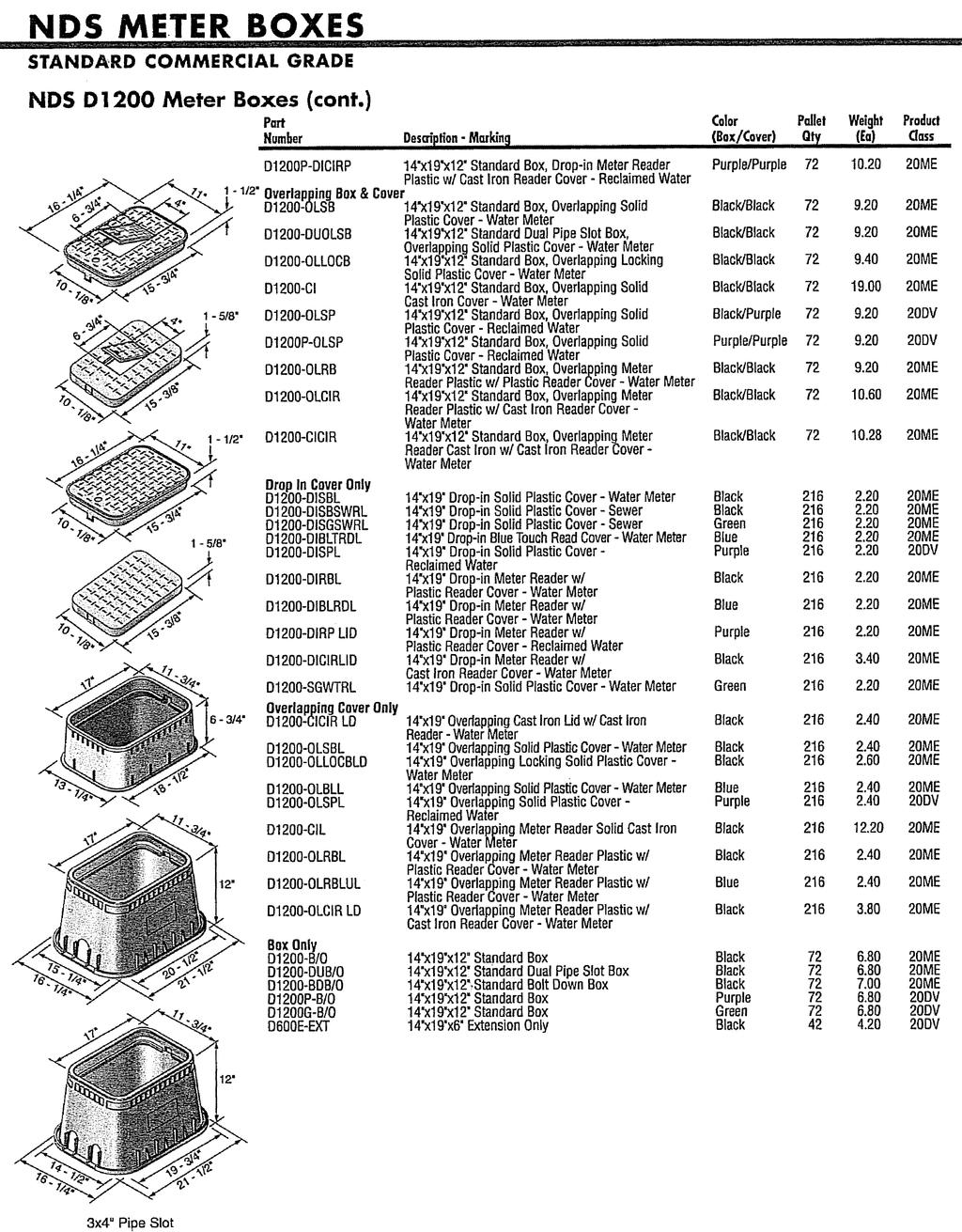
114