Principles of Foundation Engineering
|
|
|
- Suzanna Goodwin
- 5 years ago
- Views:
Transcription
1 Principles of Foundation Engineering Braja M. Das Chapter 14 Soil Improvement and Ground Modification 1
2 Spreadsheets There are spreadsheets on the class website in zip files that may useful on the projects. They include: Atterberg Limit Correlations SPT Correlations Soil Parameters After Surcharging 2
3 Additional CPT Correlations m 62.4 ( 0.27log ( FR) 0.36 log( qt) ) qt o c 3 qt o S u 15 tan log qt o M 5 qt o m = unit weight in pcf FR = friction ratio (%) qt = point resistance in tsf c = preconsolidation pressure in tsf Su = undrained shear strength in tsf o = total stress in tsf o = effective stress in tsf = friction angle M = constrained modulus in tsf E = elastic modulus in tsf = poissons ratio [ M[ ( 1 ) ( 1 2 )]] E ( 1 ) 3
4 Ground Improvement We have learned the various methods for supporting structures using foundations systems that are dictated by the subsurface conditions at the site. Shallow foundations competent shallow soils for BC & settlement Deep foundations - carry the structural loads to more competent soils at depth A deep foundation system is used when shallow soils are problematical. If the shallow soils could only be better! We could use a less costly foundation system or use the unusable site. 4
5 Types of Ground Improvement Ground improvement falls within two broad categories. Modification of soil properties Preloading Surcharging Dynamic Compaction Reinforcement Soft Inclusions Hard Inclusions 5
6 Modification of Soil Properties 6
7 Preloading & Surcharging Preloading create preconsolidation by using a substitute to mimic the loads imposed by the new structure. Surcharging create preconsolidation by using a substitute to mimic more than the loads imposed by the new structure. In both cases, the substitute is removed and then the new structure is built. Typically, the substitute is soil and/or rock. 7
8 Preloading The concept in preloading is to make the subsurface move in response to the anticipated structural loading. Once the preloading is removed, the subsurface will not know that the structure is there. Caveat rebound and recompression The modification to the soil is a change in the preconsolidation pressure c. The added bonus is increased strength. Partial preloading is to preconsolidate so that the remaining settlement is within tolerable or the increase in strength meets design needs. 8
9 Increased Strength S uoc oc S unc nc OCR S unc S uoc ( ) oc nc OCR where S u / oc = overconsolidated undrained strength ratio S u / nc = normally consolidated undrained strength ratio OCR = overconsolidation ratio c / o = 1-(Cs/Cc) (0.6 to 1.0, avg 0.8) 9
10 How Much to Preload? The amount of stress increase created by preloading should equal or exceed the stress increase created by all aspects of the new structure. Structural fill Stress imposed by foundations (Westergaard) Maximum sustained floor loading Recompression Other project specific loading (architects) 10
 = 540 psf avg = 1/6(@top +4(@mid)+ @bot) avg = 1/6(900+4(690)+540) = 700 psf If preloading fill weighs 115 pcf, then to create 700 psf loading use 700/115 = 6.")
11 Example Using 3000 psf,b=5, & Westergaard First clay D/B = 4/5 = 0.8B so I = = 0.3(3000) = 900 D/B = 5/5 = 1B so I = = 0.23(3000) = 690 D/B = 6/5 = 1.2B so I = = 0.18(3000) = 540 psf avg = 1/6(@top avg = 1/6(900+4(690)+540) = 700 psf If preloading fill weighs 115 pcf, then to create 700 psf loading use 700/115 = 6.1 of surcharge fill and round to 6 Since stress on second layer would be less, preloading for the first layer would exceed that needed for second layer. 11
12 Time to Complete Preloading The time required for a preloading program should fit within the construction schedule. If that time is too long, the process must be accelerated. t T H2 c v 12
13 Surcharge for Accelerating 0% 0% Example 4 feet structure fill is needed for a project. The fill will settle 3 inches. The calculated time for settlement is %. Average Degree of Consolidation - U% 10% 20% 30% 40% 50% 60% 70% 80% 90% With Surcharge Without Surcharge 100% 100% Time Factor - Tv Large filled areas dissipate stress very little in the range of shallow soils. 10% 20% 30% 40% 50% 60% 70% 80% 90% % Total Settlement How can we decrease time needed to 90 days? Tv for 90 days is 50% of Tv for 180. Tv(90) = 0.5(0.8) = equals 70% U% for a higher loading by adding surcharge above preloading. If settlement was allowed to go to 90% for both preloading and surcharge, it would equal 3/0.7 = 4.3. Use 5. Recalculate settlement by adding more fill above 4 feet until until 5 is obtained. The difference between it and 4 feet is the surcharge needed. Approximation is (5/3)(4 ) = 6.6 Use 7. Add 3 feet of surcharge and stop when settlement in field is 3 inches. 13
14 Failure Preloading and surcharging must also be evaluated for overstressing the soft soils creating a stability failure. Slope stability failure Plastic flow H > 2 / 3 c Such movements may be interpreted as additional consolidation settlement. Norfolk NAS runway an example. 14
15 Other Means to Accelerate Since the time required for settlement to occur is dependent on the square of the height of the pore water path t T H2 c v Why don t we reduce H? 15

16 Prefabricated Vertical Drain (PVD) t T H2 c v For quick and dirty estimate, make H = wick spacing or put t = desired time and solve for H. 16
17 Layout of square-grid pattern of prefabricated vertical drains 17
18 Time for Settlement With Drains t = (D 2 / 8 c h )(F(n) + Fs + Fr) ln (1/1-U h )) Where: t = time required to achieve the desired consolidation U h = average degree of consolidation desired D = diameter of zone of influence of the wick drain c h = coefficient of consolidation for horizontal drainage F(n) = drain spacing factor = ln(d/d w ) 0.75 d w = equivalent diameter = 2(a+b)/, where a = width of drain and b = thickness of drain Fs = soil distance factor = ((k h /k s ) - 1) ln(d s /d w ) k h = coefficient of horizontal permeability in the undisturbed soil k s = coefficient of permeability in the disturbed or smear soil zone ds = diameter of the idealized disturbed zone around the drain Fr = factor for drain resistance = z (L-z) (k h /q w ) z = distance below the top surface of the compressible layer L = effective drain length, i.e., total drain length when drainage occurs at one end only, half length when drainage occurs at both ends q w = discharge capacity of the wick drain at a gradient of 1 Spreadsheet on Web Site 18
19 Disturbed or Smear Zone Size of Zone Hansbro 1.5 to 3 x dw Bergado 2 x dw Xiao 4 to 8 x dw Cavity Expansion Theory (CET)Model 4 x dw Normalized Permeability Model 2.5 x dw Normalized Water Content Model 2.5 x dw Permeability of Zone Using Reduction Ratio kh/ks Hansbro (1981) 2 to 6 Hansbro (1997) ks = kv Ratio of kh to kv Sands and Gravels 1 Predominantly Silts 2 to 3 Predominantly Clays 5 to 8 19


20 Installation of PVDs in the field 20


21 PVD Installed 21


22 Strip Drains 22


23 Monitoring 23


24 Surcharging 24
25 Pore Pressure Transducers Pore Pressure Transducers w Z Degree of Consolidation 100% 0% 25


26 Transducer Data 26
27 Settlement Plates EMBANKMENT FILL SURFACE STD. PIPE CAP, 1" MAX. ABOVE RISER 3" SCH. 40 PIPE CASING, 4'-0" SECTIONS, THREADED BOTH ENDS STD. SCREW FITTING/COUPLING TO MATCH RISER PIPE, WELDED TO PLATE 4" OAKUM OR SIMILAR COMPRESSIBLE MATERIAL BENEATH 3" CASING 1-1/2" SCH. 40 BLACK PIPE RISER, 4'-0" SECTIONS, THREADED BOTH ENDS PROTECTIVE CASING FILLED WITH SAND, 55 GAL. DRUM CUT IN HALF OR SIMILAR 3'-0" x 3'-0" x 1/8" STEEL PLATE, A36 4'-0" x 4'-0" x 4" COMPACTED SAND BASE ± 1' BELOW FINAL SUBGRADE 27

28 Settlement Cells A settlement cell consists of a liquid reservoir, liquid-filled tubing, and the settlement cell, which contains a pressure transducer. One end of the tubing is connected to the settlement cell, which is embedded in fill or installed in a borehole. The other end of the tubing is connected to the reservoir, which is located away from the construction area. The transducer measures the pressure created by the column of liquid in the tubing. As the transducer settles with the surrounding ground, the height of the column is increased and the settlement cell measures higher pressure. Settlement is calculated by converting the change in pressure to millimeters or inches of liquid head. 28

29 Borehole Installed Settlement Cell A borehole is drilled which allows a pressure transducer to be anchored to solid ground below the area of settlement. A fluid filled tube extends upward connecting the transducer to a reservoir which is located in the moving strata or fill. The measurement of fluid pressure indicates the elevation difference between the sensor and the reservoir. Eliminates the need for separate tubing going to a reservoir like the settlement cell. 29
30 Other Monitoring Devices Extensometers multiple level monitoring Horizontal Slope Indicators vertical settlement profile Vertical Slope Indicators horizontal movement (plastic flow or failure) 30
31 Settlement Plate Data Settlement Plate Data Plate 1 Plate 2 Plate 3 Settlement (inches) Fill & Surcharge Construction Monitoring Period Time (days) Plate 4 Plate 5 Plate 6 Plate 7 Plate 8 Plate 9 Plate 10 Plate 11 Plate 12 Average 31

32 Settlement Cell Data 32

33 Extensometer Data 33
34 Log Plots Settlement (cm) SC-1 SC-2 SC-3 EXT-1 EXT Days 34
35 Pore Pressure Response 14 Estimated Pore Pressure Response During Fill Construction Loading Equivalent to 8 Feet of Fill Using Multilayer Theory Note: Dashed Lines Indicate Construction Phase Depth (feet) Actual Time (days) Excess Pore Pressure (psf) 35
36 By Layer Pore Pressure Response 1200 Estimated Pore Pressure Response Using Multilayer Theory Initial Instantaneous Loading Eqivalent to 8 Feet of Fill 1000 Excess Pore Pressure (psf) Depth (ft.) Time After Load Application (days) 36
37 Predicted Versus Actual Average of Settlement Plates Predicted Average Settlement Based on Pore Pressure Response Settlement (inches) Time (days) 37
38 Dynamic Compaction Dynamic compaction is a method for compacting soils at depth, even below the groundwater table. A large weight is raised on a modified crane and dropped from a design height. The weight impact on the ground densifies the soil beneath to depths that are dependent of the energy imparted. Most effective in sand soils with less than 30% fine grained material Groundwater depths of 5 feet or deeper. 38


39 Dynamic Compaction Equipment 39

40 Densification at Depth 40
41 Depth of Improvement 41
42 Measuring Improvement Effectiveness of dynamic must be evaluated. Adequate data prior to DC must be obtained CPT Data SPT Data Comparative data is obtained after DC to directly measure improvement. Sometimes improvement not shown immediately. The amount of fill used to backfill the drop can be used for an overall measure of densification. 42
43 Variation of standard penetration resistance before and after compaction 43

44 Rapid Impact Compaction For shallow densification <10 feet 44
45 Reinforcement 45
46 Ground Reinforcement If we cannot change the soil properties directly, added stronger elements to improve global strength. Two types, rigid and soft inclusions. 46
47 Soft Inclusions Inclusions are considered to be soft when: the inclusion material has minimal cohesive properties typically constructed with a granular material with stiffness 5 to 10 times larger require lateral confinement from the surrounding soil some amount of lateral deformation must occur before the granular material is sufficiently engaged and confined by the surrounding soils. Soft inclusions: are often cylindrical in shape and installed on a regular grid pattern both the diameter and spacing of the inclusions are considered replacement ratio (surface area of inclusion over unit area of treatment grid) is the most commonly understood design parameter. replacement ratios for soft inclusions are on the order of 10 to 30% of the soil mass. are installed using a variety of methods which penetrate, vibrate, or auger through the unimproved soil mass to create a cavity for the introduction of granular materials. use vibratory probes and/or ramming components are used to densify the granular materials. Depending on the technique, the installation methods may greatly modify the properties of the in situ soil mass, thereby modifying the performance of the soft inclusion. are not used in strict settlement criteria projects 47
48 Types of Soft Inclusions Vibrofloatation Stone Columns Rammed Aggregate Piers 48
49 Rigid Inclusions Inclusions are considered to be rigid when: the inclusion material displays a significant permanent cohesion or strength the stiffness of the inclusion is much larger than that of the surrounding soil, thereby attracting a larger portion of the applied loads. instead of truly improving the soil, the rigid inclusion acts as a reinforcement of the soil mass. due to the strong cohesion or strength of the material, rigid inclusions do not rely on the confinement of the soil for stability and performance. Rigid inclusions are often smaller in diameter than soft inclusions ranging from 200 mm (8 in.) to around 800 mm (32 in.). Nevertheless, much larger elements have been used in large scale projects. Typical replacement ratios are much smaller than soft inclusions; on the order of 2% to 12% of the soil mass. 49
50 Types of Rigid Inclusions The technique has many different appellations depending on the countries and the inclusions themselves can be built with various materials and installation techniques. Deep Soil Mixed Columns Jet Grouting Columns Vibro-Concrete Columns Controlled Modulus Columns (CMCs) Piles 50
51 Differences Between Inclusion Types variation in the stiffness and cohesion differences in the load transfer mechanisms and behavior assumptions specific to their respective installation methods and design methodologies. the soft inclusions reliance of confinement of the surrounding soil, the plasticity of the soft inclusion must be carefully considered in the design process. because the material used to build rigid inclusions is usually a cementitious mix or steel, each inclusion usually exhibits small and nearly elastic deformations soft inclusions will often exhibit significant plastic deformations under loading dependent on the inclusion stiffness and lateral confinement available. 51

52 Concept Placement of fill directly on soft marsh soils Fill Stone column reinforced marsh soils. Soft marsh soils Marsh soils fail, displaced by fill soils and mud waves occur. Mud Wave More competent soils. Less settlement on stone column reinforced marsh soils 52


53 The Obvious Undercut soft marsh soils substantially wider than fill base to prevent loading soft soils. Place fill soil or stone. 53

54 Footing Undercut & Replace 54
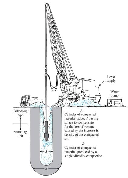
55 Vibroflotation 55
56 Nature of probe spacing for vibroflotation 56


57 Rammed Aggregate Piers Rammed Aggregate Piers are installed by constructing successive layers of densely compacted aggregate in a drilled or excavated shaft, typically measuring between 24 and 36 inches in diameter. 1. Drill a cavity to depths ranging from 7 to 30 feet deep. 2. Place a 12-inch layer of open-graded aggregate at the bottom of the cavity. 3. Compact the aggregate using a tamper that delivers a high-energy impact ramming action. The ramming action compacts the aggregate and prestresses the surrounding soil. Successive lifts of well-graded aggregate are then rammed in place. 57
58 RAP Calculations Estimated Settlement of Geopier Reinforced Soil Convergence Center V GP Diameter (in.) = Area (ft^2) = 4.91 SAB 10/14/13 Boring No Footing Estimated GP GP #GP Calc. Design Design Area UZ Soil GP Stress Area GP qp/q Soil UZ LZ LZ LZ LZ Total or Footing Load Design q Depth Capacity Reqd. Width Width Length A Es km kp Ratio Ratio qp Ratio qm Settlement Es Dq q Settlement Settlement Type k or klf ksf ft k ft ft ft ft^2 ksf pci pci Rs Ra ksf ksf in ksf ksf in in CPT CPT CPT CPT CPT CPT CPT CPT Typical Range of Values Enter data in BLUE fields only Notes: Estimate soil k for column footing from plate load theory Column A - square footing is assumed unless "wall" is entered. k = Es / B Column C - assume a design or service level bearing stress. Es= 200 ksf adjust for strip footings due to small B Column D - estimate the appropriate installed length below the footing. B= 7.5 ft Column E - estimate individual geopier capacity from typical values table on Sheet 2. k= kcf Column H and I - round up the calculated width and add length pcf Column K - enter an assumed upper zone elastic modulus for the soil pci reduce k for strip footngs as req'd Column M - estimate the geopier modulus from typical values table on Sheet 2. Column T - enter an assumed soil modulus for the soil below the geopiers. In saturated clay, LZ settlement may be estimated from consolidation settlement calculations, or an equivalent constrained modulus from in-situ tests or consolidation tests. THESE ESTIMATES ARE ALWAYS PRELIMINARY AND FINAL DESIGN PARAMETERS AND SETTLEMENT PREDICTIONS WILL BE PROVIDED BY THE GEOPIER CONTRACTOR. 58
59 RAP Under Footings WALL OR COLUMN BEARING DEPTH - 2.5' MIN. FOOTING UPLIFT TENDONS AS NECESSARY GEOPIER ELEMENT LENGTH AS SPECIFIED 59
60 Plan view and unit cell idealization of stone column 60
61 Stone Columns 61
62 Calculations Stone Column Capacity of stone column = 40 degrees Safety Factor = 3 Ultimate Capacity (kips) Allowable Capacity (kips) Soil Strength (Cu) = 750 psf 2 foot 2½ foot 3 foot 3½ foot 4 foot 2 foot 2½ foot 3 foot 3½ foot 4 foot Date Method c/cu c Column Column Column Column Column Column Column Column Column Column 1915 Bell Vesic Hughes/Withers Brauns Hughes/Withers Geometric Mean = Standard Deviation = Mean = Theoretical Column Diameter Column Stone up to 4" size = 2.8 feet Column Stone < 1.6"size = 2.2 feet Ideal for Finite Element Analysis 62
63 Ultimate Capacity of Stone Columns u tan 2 q 45 4c u r 2 Qu 4 D2 tan c u r 2 r 2cu Qu DLcu 63
64 Settlement of Stone Columns Se Se Q LE clay I d Q 1 LE clay I d For Q<=Q1 Q Q 1 4LE clay I d For Q1<=Q<=Qu Q1 0.1DLE clay Id 64
65 Settlement (continued) K E col E clay 65
 through a nozzle of small diameter.")
66 Grout/Lime Injection Jet grouting is an in-situ mixing of soils with a stabilizer (usually neat cement grout). The stabilizer is injected at very high pressures (between 300 and 600 bar) through a nozzle of small diameter. The grout is injected at high velocity, which enables the jet grouting process to destroy the natural matrix of the soil and creates a mixing of the stabilizer with the in-situ soils. The result is a homogeneous and continuous structural element with predetermined characteristics. 66
67 Variation of liquid limit, plasticity index, and shrinkage of a clay with lime additive 67
, aggregate grout is pumped in stages, forming grout bulbs, which displace and densify the surrounding soils.")
68 Compaction Grouting Compaction grouting uses displacement to improve ground conditions. A very viscous (lowmobility), aggregate grout is pumped in stages, forming grout bulbs, which displace and densify the surrounding soils. Significant improvement can be achieved by sequencing the grouting work from primary to secondary to tertiary locations. 68

69 Controlled Modulus Columns The Controlled Modulus Columns are well adapted to high surface loading conditions and strict settlement requirements and are used to support slabs-on-grade, isolated footings and embankments on compressible clays, fills and organic soils. A specially designed auger, powered by equipment with large torque capacity and high static down thrust, displaces the soil laterally, with virtually no spoil or vibration. During the auger extraction process, a column is developed by pressure-grouting to achieve a predetermined stiffness ratio with the surrounding soil. The result is a composite soil/cement ground improvement system. 69
70 Homework No Homework Work on Project There may be a problem from Chapter 14 on the final exam. 70