Large-Scale Real-Time Hybrid Simulations
|
|
|
- Maude Zoe Fisher
- 5 years ago
- Views:
Transcription


1 Large-Scale Real-Time Hybrid Simulations Yunbyeong Chae, Ph.D. Assistant Professor Department of Civil and Environmental Engineering Old Dominion University


2 Large-Scale Real-Time Hybrid Simulation for A 3-Story Steel Frame with MR Dampers Test conducted at: Lehigh University Bethlehem, PA


3 Prototype Building Structure Floor plan Elevation MRF DBF MRF MRF DBF Gravity frame MRF 3 Analytical substructure: 2 MRF + Gravity frames 1 Ground Base DBF 3 Experimental 2 substructure: Gravity DBF frame + MR dampers 1 Ground 6@25'=150' Tributary Area for EW EQ EQ ground motion EW direction 6@25'=150' Base
 to consider P- Delta effect Number of DOFs=148 Number of NL")
4 Analytical Substructure MRF & Gravity Frames (Lean on column) Structural modeling using HybridFEM (Karavasilis and Ricles 2009) Nonlinear displacement based beam-column fiber element for columns and beams Nonlinear panel zone element for beam-column joints Lean-on column representing gravity columns (with geometric nonlinearity) to consider P- Delta effect Number of DOFs=148 Number of NL elements=41 RBS Rigid floor diaphragm M3 M2 Panel zone element M1 Fiber elements MRF Lean-on column


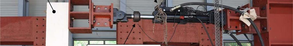
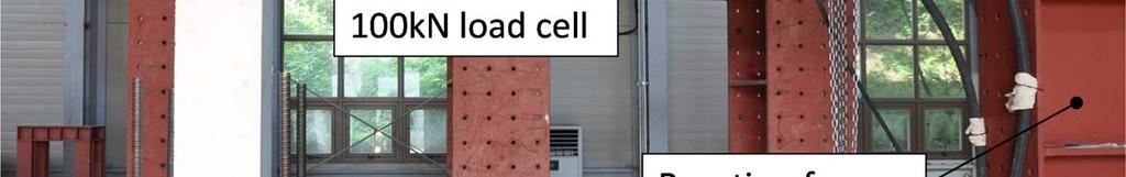
5 Experimental Substructure DBF with Two MR Dampers Bracing Frame 3 rd floor actuator (1,700 kn) DBF 2 nd story MR damper 2 nd floor actuator (2,300 kn) 1 st story MR damper 1 st floor actuator (2,300 kn)
 Adaptive coefficients are optimally updated to minimize the error between the target and measured actuator displacement using the least squares method Input target disp x t u k c compensator a")
6 Adaptive Time Series (ATS) Compensator (Chae et al. 2013) Adaptive coefficients are optimally updated to minimize the error between the target and measured actuator displacement using the least squares method Input target disp x t u k c compensator a 0k x k t a 1k x k t a 2k x k t compensated displacement u c Servo-hydraulic actuator Output measured disp x m a 0k, a 1k, a 2k A= X T m X m -1 X m T U c Coefficients identification using least squares method Chae, Y., Kazemibidokhti, K., and Ricles, J.M. (2013). Adaptive time series compensator for delay compensation of servohydraulic actuator systems for real-time hybrid simulation, Earthquake Engineering and Structural Dynamics, DOI: / eqe.2294.


7 Adaptive Time Series (ATS) Compensator Unique features of ATS compensator No user-defined adaptive gains applicable for large-scale structures susceptible to damage (i.e., concrete structures) Negates both variable time delay and variable amplitude response Time delay and amplitude response factor can be easily estimated from the identified coefficients Amplitude response: Time delay: a a 1k 0k A 1 a 0k
8 Adaptive Time Series (ATS) Compensator - Performance Comparison - Synchronization subspace plot: relationship between the target and measured displacements Measured displacement (mm) Measured displacement (mm) No compensation NRMS=16.3% Target displacement (mm) 2 nd order compensator NRMS=2.6% Target displacement (mm) Measured displacement (mm) Measured displacement (mm) Inverse compensation NRMS=2.9% Target displacement (mm) ATS compensator NRMS=1.4% Target displacement (mm)
9 RTHS: 1994 Northridge EQ (80% DBE), LQR Control
10 RTHS: Maximum Story Drift 1992 Landers (60% DBE) 1994 Northridge (80% DBE) 3 rd story No damper Passive LQR PAC 3 rd story No damper Passive LQR PAC 2 nd story No damper Passive LQR PAC 2 nd story No damper Passive LQR PAC 1 st story No damper Passive LQR PAC 1 st story No damper Passive LQR PAC Story drift (%) Story drift (%)
 0.81s 1994 Northridge (80% DBE) PAC No damper Passive LQR PAC 1 0.5 0 0 = 0.5 = 1 1.5 2 2.5 0.26s 0.")
11 RTHS: 3rd Floor Spectral Acceleration - for Nonstructural Component - Spectral acceleration (g) No damper Passive LQR 0 0 = 0.5 = =0.13s =0.13s 0.26s 1992 Landers (60% DBE) 0.81s 1994 Northridge (80% DBE) PAC No damper Passive LQR PAC = 0.5 = s 0.81s Period (sec)


12 Multi-Grid Real-Time Hybrid Simulation with 2 MR Dampers + Multiple xpcs & SCRAMNet Solve equations of motion with multiple xpcs and communication via SCRAMNet Experimental substructure Test conducted at Lehigh University, Bethlehem, PA


13 9-Story ASCE Benchmark Structure Ohtori et al. 2004, ASCE Journal of Engineering Mechanics, 130(4),

14 Deployment of MR dampers after Simplified Design Procedure MR damper Number of MR dampers 1 damper 1 damper 1 damper 2 dampers 2 dampers 5 dampers 5 dampers 10 dampers 10 dampers
 Experimental")
15 Schematic of Real-Time Hybrid Simulation Structure with MR dampers 1 st story MR damper + Actuators 2 nd story MR damper Analytical substructure modeled using HybridFEM (236 dofs, 152 NL elements) Experimental substructure


 xpc2 Analytical")

 xpc2: Intel Pentium 4 (2.")
16 Multi-Grid Real-Time Hybrid Simulation xpc1 Ground motion Update accelerations from equations of motion Integration algorithm Update displacements/ velocities Structural response + Experimental substructure restoring forces (from two MR dampers) xpc2 Analytical restoring forces xpc1: Intel Core 2 Duo (2.66GHz CPU), 2GB RAM; runs at 512Hz (1/512sec) xpc2: Intel Pentium 4 (2.4GHz CPU), 1GB RAM; runs at 102.4Hz (5/512sec)
17 Multi-Grid RTHS EQ input: 1994 Northridge earthquake
18 Comparison of Normalized TET Task Execution Time (TET): the amount of time needed to complete a single step during real-time hybrid simulation xpc1 With Two xpcs xpc2 xpc1 only Maximum TET (TET max, sec) Running time step (δt, sec) 1/512 (=0.0019) 5/512 (=0.0098) 1/512 (=0.0019) xpc1 xpc TET max t xpc with two xpcs xpc1 only


19 Slow and Real-Time Hybrid Simulations for Concrete Bridge Piers Test conducted in the Hybrid Structural Testing Center (HYSTEC) at Myongji University, Yongin, South Korea Collaborative research with Prof. Chul-Young Kim
20 Prototype Bridge Structure Typical two-span bridge with prestressed concrete girders T-shape reinforced concrete pier in the middle (experimental substructure) Remaining structural systems are modeled analytically (analytical substructure) Mass of the bridge is determined to have a natural period of T=0.8 sec Prestressed concrete girder Bridge deck Abutment Reinforced concrete pier (Experimental substructure) Direction of ground motion ( ) Pier cap beam Reinforced concrete pier (Experimental substructure)
21 Reinforced Concrete Pier Elevation (unit: mm)


22 1.55m Experimental Test Setup
23 Predefined Displacement Tests Apply the same displacement pattern for slow and fast tests Maximum velocity for slow test = 2.1 mm/sec Maximum velocity for fast test = 220 mm/sec ATS compensator used Disp. (mm) Displacement history for slow test Fast test Slow test B A Disp. (mm) Time (sec) Displacement history for fast test Time (sec) Shear Force (kn) Disp. (mm)
24 Slow Vs Real-Time Hybrid Simulations Comparison of Bridge deck displacement under the 1940 El Centro EQ u(t) (mm) SHS RTHS Time (sec) Force-displacement relationship of pier Shear force (kn) SHS RTHS u(t) (mm)
25 Slow Vs Real-Time Hybrid Simulations
26 Concluding Remarks Current status of real-time hybrid simulation Mainly focused on developing actuator control algorithms, time integration methods, and stability issues Mostly conducted for small scale and simple structures not for large-scale structures Future of real-time hybrid simulation Use of multiple actuators for large-scale structures Simulation of force boundary conditions (e.g., P-Delta effect) Will be widely used for effectively evaluating the performance of various structural systems under earthquake or wind loadings
27 Thank you!