Global Performance of Lateral Drift and Gravity Load Tests for Prefabricated Stair Assemblies as Manufactured by Pacific Stair Company
|
|
|
- Gregory Lang
- 5 years ago
- Views:
Transcription
1 Global Performance of Lateral Drift and Gravity Load Tests for Prefabricated Stair Assemblies as Manufactured by Pacific Stair Company Christopher Higgins Associate Professor of Structural Engineering Report No B Kiewit Center for Infrastructure and Transportation Department of Civil, Construction, and Environmental Engineering Oregon State University Corvallis, OR July 8, 2005
2 Introduction Stairs serve as a primary means of egress from a structure after an earthquake and thus their role in achieving life-safety performance for a building is critical. As a result of newly adopted performance-based design provisions for buildings, the lateral drift performance of prefabricated stair assemblies during seismic events has become of interest to some designers. No standardized testing methods or loading protocols are currently available for evaluating the seismic performance of prefabricated stair assemblies. Further, data on the structural performance of stair assemblies under lateral and combined lateral and gravity loading are lacking. Objectives To assist Pacific Stair Co. of Salem, Oregon in addressing issues regarding lateral-drift performance of prefabricated stair assemblies during seismic events, laboratory tests were recommended by KPFF of Portland, Oregon. The main objectives of the laboratory tests were: Develop a testing protocol to evaluate the seismic performance of production-run prefabricated stair assemblies. Apply lateral displacements to production-run prefabricated stair assemblies to simulate seismic interstory drift demands. Apply factored gravity loads to production-run prefabricated stair assemblies during and after lateral displacements. Measure response of production-run prefabricated stair assemblies under applied lateral displacements and gravity loads. Two full-size production-run stair assemblies were tested in the Structural Engineering Research Laboratory at Oregon State University to assess seismic performance and the global performance of the assemblies are described in this report. 1
3 Specimen Description Two full-size stair assemblies were fabricated by Pacific Stair Co. of Salem, Oregon. The stairs were production-run units designed for a typical steel frame building with 12 ft story heights and one intermediate landing between floor levels, a commonly encountered application. After fabrication, the stairs were shipped to the Structural Engineering Research Laboratory at Oregon State University for assembly, instrumentation, and testing. Each stair set consisted of two flights, a single intermediate landing, and 4 support columns as illustrated in Figs. 1 and 2. Complete shop drawings are contained in Appendix A. The two stair assemblies were similar except for the stair tread and landing surface. One set was fabricated with 14 gauge diamond or checker plate (Checker), the other was fabricated with 14 gauge steel pans to permit concrete in-fill (Infill). Each of the two flights of stairs consisted of 10 treads with each tread having a 6.55 in. rise and 11 in. run. Stringers consisted of ASTM-A x 10 in. plate. Stair tread plates were fillet welded to the stringers. The landing area was 4 ft x 7 ft - 10 in. and supported by ASTM-A36 C8x11.5 and C6x8.2 channel framing. Vertical support to the landing was provided by four ASTM-A36 2.5x2.5x0.25 angle columns bolted to each corner of the landing. Connections at the base of each flight of stairs consisted of ASTM-A36 5x3x0.25 angle fillet welded to the stringers. Connections at the top of each flight of stairs consisted of ASTM-A x4 in. plate fillet welded to the stringers. The top and bottom connections to the flight was made with two 5/8" diameter 1.5 in. A325 TC bolts. Other bolted connections between stair assembly pieces were also made with 5/8" diameter 1.5 in. A325 TC bolts. One test specimen (Infill) required placement of concrete in the tread form pans and the landing. The landing consisted of 20 gauge BR decking with the ribs oriented in the short landing dimension. Minimum height of the concrete overfill in the decking was 1.5 in. Thickness of the concrete in the stair tread pans was also 1.5 in. Concrete was provided by a local ready mix supplier and consisted of 1330 lbs of 3/8 in. maximum size aggregate, 2290 lbs of sand, 90 lbs of 2
4 flyash, 635 lbs of cement, 4 oz. air-entraining admixture, 28 oz. water reducing admixture, and 14 gallons of water. Concrete was placed in the pans and brush finished. The average compressive strength on the first day of testing (7 day strength) was 2000 psi, as determined from 12 in. cylinders. Instrumentation, Test Set-up, and Methodology Specimens were instrumented with displacement transducers and strain gages to measure the response during tests. Data from sensors were acquired using 16-bit PC-based data acquisition system and were continuously acquired at a high sampling rate during tests. The stair assemblies were placed in a loading frame as shown in Fig. 3 and 4. The top landing was attached to an ASTM A600 6x6x0.25 in. tube. The tube dimensions were selected to approximate the concrete landing slab dimensions and force transfer mechanism for an actual stair assembly in a building. A unique guiding system was developed to permit only in-plane deformations at the top landing attachment location as shown in Figs. 5 and 6. This was necessary to prevent uplift and out-of-plane deformations during lateral tests that are not possible if the stairs were located in an actual building subjected to lateral drift. Special radial and axial bearings were mounted to the steel tube and guided by special profile rails to restrict deformations to the in-plane directions. Stair tests were performed in each direction separately. The steel tube landing was displaced during testing using a hydraulic actuator that was operated under displacement control using a closed-loop servo-hydraulic system. Currently, no standardized seismic testing protocols for prefabricated stair assemblies exist. However, ATC-24 (1992) provides guidelines for cyclic seismic testing of components of steel structures. In general, these procedures are based on the yield level of the component, which may not be appropriate for a stair assembly. The stair assembly within a building, does not provide 3
5 significant lateral stiffness or force resistance, but is instead compliant with the building deformations. The production-run stair assemblies were considered for a typical application in a steel moment resisting frame (MRF). For a typical steel MRF, the interstory drift angle considered for the 2/3 MCE event was 2.5%, which corresponds to a peak lateral displacement ( bm ) of +/- 3.6 in. Using bm as the maximum cyclic displacement to be imposed on the stair specimen, the cycle amplitudes for three previous sequences of displacement cycles were scaled in proportion as ¾, ½, and ¼ of bm. Four cycles were imposed at these amplitudes as compared to the two or three cycles used in the ATC24 protocol for cycles imposed after yielding. At the start of testing, two sets of small amplitude cyclic displacements (2 cycles at 0.1 in. and 2 cycles at 0.25 in.) were applied to ensure data sensors were seated and data acquisition was properly functioning. Following these small amplitude initial cycles, six cycles were imposed at +/- 0.5 in. The complete lateral loading history is shown in Fig. 7. Because the stairs are compliant with the building deformations, and steel MRFs tend to be more flexible than many other types of lateral force resisting structural systems, the test displacement history would likely impose higher demands on the stair assembly than those required for many other building types. Current AISC LRFD (2003) specification load combinations require consideration of live and dead loads with earthquake loading. The specified load combination is: U = 1.2D + 0.5L E [1] where U is the factored load combination, D is the dead load, L is the service live load, and E is the earthquake load. The applied lateral load was considered to be at the load factor of 1.0 and the in-place stair assembly represented 1.0D, however additional gravity load was required to account for the additional 20% dead load and 50% service live load. For stairs, the specified service live load is 100 psf and thus the live load for the earthquake combination is 50 psf. The dead load of the stairs was provided by the manufacturer as 1463 lbs and 1262 lbs for the checker plate and 4
6 infill concrete treads (without concrete), respectively. The total dead load of the concrete in-fill stair including the weight of concrete was approximately 3300 lbs assuming normal weight concrete. Individual concrete blocks weighing between 195 and 210 lbs were cast for each step and two large blocks weighing 820 and 840 lbs (1660 lbs total) were cast for the landing. The required weight for Eqn. 1 load combination was 178 and 190 lbs/step and 1660 and 1775 lbs/landing for the checker plate and infill concrete specimens, respectively. The total weight of the blocks applied to the stair specimen was 5,700 lbs and exceeded the load factor combination in Eqn. 1 for both specimens (5,575 lbs for infill and 5,220 lbs for checker plate). The blocks were placed on the specimen prior application of the lateral load and remained in place during lateral displacement testing as shown in Fig. 3. After completion of lateral displacement testing protocol, the top landing displacement was returned to the original neutral position. The AISC LRFD (2003) specification full design live load combination was applied to the specimen as: U = 1.2D L [2] Additional concrete blocks were placed on the specimen to represent the additional factored live load (110 psf above the previous level in Eqn. 1). Individual concrete blocks weighing between 390 and 400 lbs were placed on each step and two large blocks weighing 1,735 and 1,755 lbs (3,490 lbs total) were placed on the landing. These new blocks were placed on top of the previous sets of blocks. The total required weight for this load combination was 548 and 560 lbs/step and 5,106 and 5,221 lbs/landing for the checker plate and infill concrete specimens, respectively. The total weight of the blocks applied to the stair specimens was 17,030 lbs (two sets of blocks stacked on top of each other) and exceeded the load factor combination in Eqn. 2 for both specimens (16,421 lbs for infill and 16,066 lbs for checker plate). A specimen loaded with the concrete blocks representing this load combination is shown in Fig. 8. 5
7 To account for a possible aftershock event that may occur as the stairs are subjected to the full design live load, the following load combination was considered: U = 1.2D + 1.6L E [3] For this test, four (4) cycles of lateral displacement of +/- 0.5 bm (=+/-1.8 in.) were applied when the specimen was loaded with the concrete blocks representing the full design live load. Each stair specimen was subjected to lateral displacements imposed in the two orthogonal directions separately. To achieve the performance requirements, the specimen was expected to survive both events without loss of gravity load carrying capacity. The combined testing history for each specimen consisted of the following: Application of 0.2D+0.5L gravity load blocks (Fig. 3) Application of complete lateral displacement history in Fig. 7 (N-S direction for checker plate specimen; E-W direction for infill specimen) [Meets Eqn. 1] Application of additional 1.1L gravity load blocks [Meets Eqn. 2] (Fig. 8) Application of four cycles +/- 0.5 bm [Meets Eqn. 3] Removal of additional 1.1L gravity load blocks Switch actuator direction Application of complete lateral displacement history in Fig. 7 (E-W direction for checker plate specimen; N-S direction for infill specimen) [Meets Eqn. 1] Application of additional 1.1L gravity load blocks [Meets Eqn. 2] Application of four cycles +/- 0.5 bm [Meets Eqn. 3] Test complete Test Results 6
8 Overall force-deformation response at the uppermost landing and the overall specimen displacement at the peak positive and negative amplitudes are reported here. Additional detailed responses are contained in. Checker Plate Specimen The checker plate specimen was loaded with concrete blocks simulating gravity load equal to that of Eqn. 1. The checker plate specimen was first subjected to lateral displacements in the transverse to stair run (north-south direction in Fig. 1). Overall force-deformation response for the transverse direction loading is shown in Fig. 9. After the lateral displacements of Fig. 7 were imposed, the specimen was returned to the original neutral position and loaded with additional concrete blocks simulating Eqn. 2 level gravity loads. The specimen sustained the load. The specimen was then subjected to 4 cycles of lateral loading with maximum displacement amplitude of +/- 0.5 bm while under the full factored design gravity load (Eqn. 3). The measured overall lateral force-top landing displacement during the aftershock test is shown in Fig. 10. The specimen exhibited stable and repeatable cyclic performance during the four cycles. During the lateral loading, the intermediate landing moved primarily in the north-south direction with relatively small displacements in the east-west direction and the overall specimen displacements at maximum positive and negative displacement amplitudes are as illustrated in Fig. 11. With the lower layer of concrete blocks remaining on the specimens (corresponding to gravity load in Eqn. 1), the checker plate specimen was subjected to lateral displacements in the parallel to stair run (east-west direction in Fig. 1). The overall force-deformation response for the parallel direction loading is shown in Fig. 12. The intermediate landing exhibited relatively large motions and rotated about the bottom landing connection as illustrated in Fig. 11. Due to the residual gaps at the landings from the previous load history, the specimen underwent some deformation before the separations closed enabling bearing of the connection parts. After the lateral displacements of 7
9 Fig. 7 were imposed, the specimen was returned to the original neutral position and loaded with additional concrete blocks simulating Eqn. 2 level gravity loads. The specimen again sustained the applied gravity load. The specimen was subjected to 4 cycles of lateral loading with maximum displacement amplitude of +/- 0.5 bm while under the full factored design gravity load (Eqn. 3). The measured overall lateral force-top landing displacement during the aftershock test is shown in Fig. 13. The specimen exhibited stable and repeatable cyclic performance during the four cycles. The checker plate specimen successfully satisfied the loading protocol by sustaining the factored gravity load under the design lateral motions in the two orthogonal directions and demonstrating full design gravity load carrying capacity combined with the aftershock lateral displacements. In-Fill Specimen Concrete was placed in the stair pans and intermediate landing deck and allowed to cure for 7 days prior to testing. Concrete blocks simulating gravity load equal to that of Eqn. 1 were then placed on the specimen. The in-fill specimen was initially subjected to lateral displacements in the parallel direction (east-west direction in Fig. 2). Overall force-deformation response for the parallel direction loading is shown in Fig. 14. The specimen exhibited relatively little lateral stiffness and energy dissipation. After the lateral displacements of Fig. 7 were imposed, the specimen was returned to the original neutral position and loaded with additional concrete blocks simulating Eqn. 2 level gravity loads. The specimen sustained the applied gravity load. The specimen was then subjected to 4 cycles of lateral loading with maximum displacement amplitude of +/- 0.5 bm while under the full factored design gravity load (Eqn 3). The measured overall lateral force-top landing displacement is shown in Fig. 15. The specimen exhibited stable and repeatable cyclic performance during the four cycles. During lateral loading, the intermediate 8
10 landing moved primarily in the east-west direction with relatively small displacements in the north-south direction as illustrated in Fig. 16. The landing displacement at the northeast corner was larger than the imposed displacement amplitude at the top landing due to rotation about the base. Minor cracking of the concrete in the intermediate landing at the intersection of the upper stair run was observed from the stringer bearing. No cracking was seen in the concrete stair pans. After lateral loading was completed, the top layer of concrete blocks was removed and the lateral loading actuator orientation was changed to permit testing of the specimen in the transverse (north-south) direction. With the lower layer of concrete blocks remaining on the specimens (corresponding to gravity load in Eqn. 1), the infill specimen was subjected to lateral displacements in the transverse direction (north-south direction in Fig. 2). The overall forcedeformation response for the transverse direction loading is shown in Fig. 17. The intermediate landing exhibited smaller amplitude motions compared to the parallel case as seen in Fig. 16. After the lateral displacements of Fig. 7 were imposed, the specimen was returned to the original neutral position and loaded with additional concrete blocks simulating Eqn. 2 level gravity loads. The specimen again sustained the applied gravity load. The specimen was subjected to 4 cycles of lateral loading with maximum displacement amplitude of +/- 0.5 bm while under the full factored design gravity load (Eqn. 3). The measured overall lateral force-top landing displacement during the aftershock test is shown in Fig. 18. The specimen exhibited stable and repeatable cyclic performance during the four cycles. The infill specimen successfully satisfied the loading protocol by sustaining the factored gravity load under the design lateral motions in the two orthogonal directions and demonstrating full design gravity load carrying capacity combined with the aftershock lateral displacements. 9
11 Summary and Conclusions Laboratory tests of prefabricated stair assemblies as manufactured by Pacific Stair Company were performed to help address issues regarding lateral-interstory drift performance during seismic events. A testing protocol was developed to evaluate the seismic performance of prefabricated stair assemblies. Two different production-run stair assembly units were tested: one with checker plate and one with concrete filled pans. The stair assemblies were subjected to lateral displacements simulating seismic interstory drift demands. Factored gravity loads were applied prior to, during, and after lateral displacements. Based on the experimental methodology and test results, the following conclusions are presented: A testing protocol was developed that incorporated combined gravity and lateral loads using AISC load combinations. Peak imposed lateral displacements were based on an interstory drift angle of +/-2.5% for a steel frame building having 12 ft story heights. Lateral displacements were imposed at the top landing location of the stair assemblies and were applied in each direction (parallel to and transverse to stair run), separately. The test apparatus constrained top landing displacements to the plane of loading, thereby imposing deformations and stresses consistent with in-situ building conditions. Both stair assemblies successfully completed the testing protocol by demonstrating full design gravity load capability after undergoing lateral displacements in both orthogonal directions. The stairs supported the full factored gravity loads while undergoing four repeated cycles of lateral displacement equal to half of the maximum seismic interstory drift after application of the lateral displacement history. There was no appreciable difference in the performance of the two stair assemblies. Overall stair performance is dependent on the connections and careful detailing and fabrication should be observed to ensure performance requirements are met. 10
12 Stair assemblies having substantially different details than those investigated may require additional analysis or testing to validate their seismic performance. The overall system performance observed in the tested stair assemblies may facilitate subassemblage testing to validate component behavior and performance. References American Institute of Steel Construction (AISC). (2003). 3 rd Edition, Load and Resistance Factor Design Specification for Structural Steel Buildings. Chicago, Illinois. Applied Technology Council. (1992). ATC-24. Guidelines for Cyclic Seismic Testing of Components of Steel Structures. Redwood City, California. 11
13 Act Disp BN3 BLK17 GN11 GN15 Purp2 BLK16 Act Disp Purp6 N BLK15 BLK14 GN13 GN9 GN10 GN14 Purp7 BLK1 GN7 BLK13 BLK2 BN4 BLK12 GN12 GN16 BLK3 GN8 Strains BN2 BN1 BLK8 BLK11 Inside BLK9 Outside Inside BLK10 Outside BLK7 Inside BLK4 Inside BLK5 Outside BLK6 Outside BLK /8" BLK19 BLK18 BLK6 56-7/8" BLK5 Strain gages Weld Bolts Top Landing Connection Plate Bottom Landing Connection Angle Fig. 1 - Stair assembly containing checker plate treads and landing. 12 total 12
14 Act Disp BL1 BL6 WT2 Gn1 Act Disp N Gn4 BL5 BL4 PR4 WT1 Gn2 PR2 BL2 Gn3 BL3 PR3 PR1 Strains BL7 BL8 Pr6 Pr7 Pr5 Pr4 96" Pr2 Pr8 35" Rd5 Rd7 Pr1 Pr3 North Face South Face Rd8 Rd6 96" Rd1 Rd3 R4 Rd2 35" Weld Bolts Strain gages Top Landing Connection Plate Fig. 2 Stair assembly containing concrete in-fill pans for treads and landing. 13


15 Fig. 3 Overall loading frame and assembly looking south. Fig. 4 Overall loading frame and assembly looking north-west. 14


")


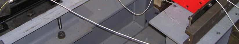
16 Actuator Motion Fig. 5 Top landing guide assembly for transverse to stair (N-S) direction loading. Actuator Motion Fig. 6 Top landing guide assembly for in-stair (E-W) direction loading. 15
 2.4 1.6 0.")


17 / Delta BM Top Landing Displacement (in) / Delta BM +/ in. +/- 0.1 in. +/- 0.5 in. +/- 0.5 Delta BM /- 1.0 Delta BM Time Fig. 7 Lateral displacement history applied to top landing in each orthogonal direction. Fig. 8 Specimen loaded with blocks simulating full factored design gravity load per Eq. 2 (blocks stacked on top of one another). 16
18 6 4.5 Lateral Load (kips) Top Landing Displacement (in) Fig. 9 Overall lateral force top landing displacement for checker plate specimen displaced in the transverse direction (N-S) during simulated earthquake test Lateral Load (kips) Top Landing Displacement (in) Fig. 10 Overall lateral force - top landing displacement for checker plate specimen displaced in the transverse direction (N-S) during simulated aftershock test. 17
19 Transverse Displacement -3.6 in in. N Parallel Displacement Fig. 11 Intermediate landing displacements at maximum and minimum displacement for checker plate specimen during simulated earthquake tests. 18
20 Lateral Load (kips) Top Landing Displacement (in) Fig. 12 Overall lateral force-top landing displacement for checker plate specimen displaced in the parallel direction (N-S) during simulated earthquake test Lateral Load (kips) Top Landing Displacement (in) Fig. 13 Overall lateral force-top landing displacement for checker plate specimen displaced in the parallel direction (E-W) during simulated aftershock test. 19
21 Lateral Load (kips) Top Landing Displacement (in) Fig. 14 Overall lateral force-top landing displacement for infill specimen displaced in the parallel direction (E-W) during simulated earthquake test Lateral Load (kips) Top Landing Displacement (in) Fig. 15 Overall lateral force-top landing displacement for infill specimen displaced in the parallel direction (E-W) during simulated aftershock test. 20
22 Transverse Displacement -3.6 in in. N Parallel Displacement Fig. 16 Intermediate landing displacements at peak top landing displacements for infill specimen. 21
23 5 4 3 Lateral Load (kips) Top Landing Displacement (in) Fig. 17 Overall lateral force-top landing displacement for infill specimen displaced in the transverse direction (N-S) during simulated earthquake test Lateral Load (kips) Top Landing Displacement (in) Fig. 18 Overall lateral force-top landing displacement for infill specimen displaced in the transverse direction (N-S) during simulated aftershock test. 22