Revised January buildingscience.com. Water Management Details. Housewraps/Flashings/Windows buildingscience.com
|
|
|
- MargaretMargaret Snow
- 5 years ago
- Views:
Transcription


1 Revised January 2007 Housewraps/Flashings/Windows BSP-020: for Residential Buildings
2 Table of Contents Introduction... 4 Water Management Concept...4 Risk Factors... 4 Building Paper/Housewraps as the Drainage Plane... 5 Installation Concerns... 6 Exposure Concerns... 7 Problems relating to cladding... 7 Brick and Stone Veneers...7 Board Siding... 8 Hard Coat Stucco, Thin Brick, and Manufactured Stone Veneer... 9 Flashings...11 Installation Concerns...11 Special Flashing Details...12 Step flashing/roof Wall connection...12 Kick out flashing...13 Other Penetrations...14 Windows...17 Installation Concerns...17 Nailing Flange...18 Pan Flashing...20 Furred Out Windows...25 Conclusion...26 Page 2 of 26 BSP-020: for Residential Buildings
3 List of Figures Figure 1: Shingle lap of drainage plane materials... 6 Figure 2: Improper installation of drainage plane materials... 6 Figure 3: Hydrophobic and hydroscopic properties... 8 Figure 4: Failed water drop test of a housewrap... 8 Figure 5: Drainage matt installed behind wood shingles... 9 Figure 6: Stucco renderings bonded to house wrap... 9 Figure 7: Control joint over top of building paper (not recommended) Figure 8: Weep screed used as a control joint with building paper shingle lapped over top of the flange Figure 9: Basic flashing principles Figure 10: Reverse sloped flashing Figure 11: Kick out flashing conceptual design Figure 12: Kick out flashing installations Figure 13: Poorly folded kick out flashing Figure 14: Electrical utility installed after water management system Figure 15: Panel installed before installation of the drainage plane Figure 16: Membrane flashed exhaust vent Figure 17: Flanged electrical box Figure 18: Saddle flashing conceptual design Figure 19: Water intrusion through the window frame Figure 20: Discontinuity of the nailing flange at the corners Figure 21: Bent and damaged nailing flanges being delivered to site Figure 22: Cracked nailing flange at corner connection Figure 23: Reverse lap of self adhered membrane at window sill in a barrier installation Figure 24: Sill and backdam options Figure 25: Drainage blocked due to exterior sheathing above the sill framing Figure 26: Tenting of the membrane pan flashing in the corner Figure 27: Torn membrane pan flashing Figure 28: Window corner cutting into improperly seated pan flashing Figure 29: "Fishmouthing" of the membrane Figure 30: Moldable membrane and preformed plastic pan flashings Figure 31: Weather seal gasket used as a backdam Figure 32: Single piece moldable membrane pan flashing with backdam Figure 33: Window furred out from the drainage plane (not recommended) Page 3 of 26 BSP-020: for Residential Buildings
4 Introduction Water management is based on the basic principles of physics. The concepts of drainage, wetting and drying potential are generally easy to understand. Explaining with graphics, text, or words what needs to be done for proper water management can be pretty straight forward, since we are dealing with ideal concepts and situations. The in field installation of these details, however, often requires some care to ensure that they perform properly. Repetitive installations and a need to get installations done quickly can lead to poor installations that can cause problems. Special guidance is sometimes needed as to how products should be installed and where special care should be taken to ensure problem free performance of the building enclosure system. Water Management Concept Controlling rain and ground water is the most important factor to designing a durable building. One of the best methods for controlling rainwater is by ensuring that water is effectively drained down and out of the building and assemblies. The various levels of drainage that are considered are as follows: Drain the site Drain the house Drain the assembly Drain the opening Drain the component Drain the material. Gravity is the driving force behind drainage, and while it can be of great use to us, if the details that we create to manage water are poorly designed, poorly installed, or deteriorate, it can create severe problems as well. Risk Factors The severity of the failure is based on several risk factors in the design and construction of the building. Water Resistance As the water penetration resistance of the assembly increases, the risk of moisture problems decreases. Moisture Tolerance of Assembly As the moisture tolerance of the materials that comprise the assembly increases (masonry and concrete vs. wood and steel) the risk of moisture related problems decreases. Exposure Page 4 of 26 BSP-020: for Residential Buildings
5 As the exposure to rainfall increases, the risk of moisture related problems increases. Rainfall As the amount of rainfall increases, the risk of moisture related problems increases. Drying Potential As the ability of an assembly to dry increases due to the climate, design, or both, the risk of moisture related problems decreases. Workmanship As the craftsmanship of the construction of the assemblies and their connection details increases, the risk of moisture related problems decreases. Some of the factors we have limited to no control over. Factors such as rainfall and exposure are often facts of life that we need to accommodate in how we design. We can reduce some of the risk with the use of water resistant (or tolerant) materials and assemblies, or by maximizing the drying potential of the systems. When it comes to liquid water intrusion however, these strategies can only protect us to a point. Some of the most severe failures occur due to poor design or installation of water management details. Blame cannot be put on one person or group for these failures, they are often a combination of tricky or difficult installation sequences, a lack of understanding of what is trying to be achieved through the detail, time pressure, and occasionally unforeseen reactions between materials. While in some locations in the assembly greater tolerances can be endured, there are critical points in any design where extra care must be taken and more refined tolerances observed in order for the system to function properly for the long term. has been working for years to develop simple, effective, and low cost methods to provide effective water management for houses. These details have been incorporated into numerous homes built under the Building America Program. Through these numerous installation, guidance for proper installation and areas that need special care, has been developed based site inspections of common reoccurring problems and improper installations, as well as from field-testing of different assemblies. Building Paper/Housewraps as the Drainage Plane An integral part of many water management systems is the use of building paper or housewraps as the drainage plane in the wall system. The basic concepts with these products are that they should always be installed in a shingle lap fashion and have enough space to drain moisture down and out to the exterior. With house wraps, the joints are often also taped to provide increased protection from water entry and to increase the air tightness of the assembly. With no other factors to consider, following these basic ideas should result in long-term performance of the material. While the concept is simple, certain construction methods and details have interfered with the performance of the house wraps and building papers. Page 5 of 26 BSP-020: for Residential Buildings


6 Figure 1: Shingle lap of drainage plane materials Installation Concerns Maintaining the shingle lap of the building paper or housewrap is generally pretty easy for the field of the wall. Problems usually appear at areas where there is a change in construction, specifically at window intersections and at roof wall connections. These are also often areas of higher liquid water concentration which further exacerbate the problem. reverse flashing reverse lap Figure 2: Improper installation of drainage plane materials Page 6 of 26 BSP-020: for Residential Buildings
7 This occurs due to improper sequencing of the construction, or though the difficulty in installing the products at areas of more complicated geometry. Often at these locations the shingle installation ideal is exchanged for coverage (As long as we get the housewrap everywhere it should be fine, right? Wrong.). When roof overhangs, or other kick outs in construction occur, the installation of the house wrap must be considered carefully to ensure that a reverse flashing is not created. While taping the joints of housewraps can reduce the risk of water entry, it is no substitute for proper shingle lapping of the product. The use of smaller pieces of housewrap or building paper at these more complicated areas can be advantageous as they are easier to handle and install. The pieces can also be cut if need be into specific shapes to deal with the more complicated geometry. The development of standard details by builders for these situations can be beneficial in the long run, to provide consistent and reliable performance of the housewrap/building paper drainage plane. Exposure Concerns Prolonged exposure of the housewraps and building papers can be a concern. Building paper if left exposed to wind and debris can tear and get damaged before the installation of the cladding system. Even housewraps, with the increased tear resistance, will tear or the holes created by the fasteners will elongate if left exposed to repetitive wind loading for extended periods of time. Tears and elongated fastener holes will create discontinuities in the field of the drainage plane, reducing its effectiveness or creating a fundamental failure in the function of the drainage plane. Due to this, it is generally recommended that the cladding system be installed as soon as possible after the housewrap or building paper. This may not always be possible, however, and in situations where the housewrap or building paper has been left exposed for a time, an inspection of the condition of the housewrap/building paper drainage plane must be done prior to installation of the cladding, with any torn or damaged housewrap/building paper repaired or replaced. This is not an ideal situation as the repaired areas are often not as effective as the original installation of the drainage plane. In addition, the UV resistance of the products varies greatly and can affect the long term performance. Building papers are not very resistant to UV damage. Many housewraps are rated for certain amounts of UV exposure; however, this varies dramatically from product to product and should be considered if prolonged exposure is expected. Problems relating to cladding All cladding materials have affected in one way or another the long-term performance of building papers and house wraps. The issues were for the most part related to poor installation techniques and workmanship, or from unforeseen compatibility problems between materials. The main fundamental problem is that water is often able to penetrate through a house wrap if the water is held against the house wrap for a given period of time. This is particularly true with all perforated house wraps, but it can also occur with non-perforated house wraps that have been exposed to surfactants. Brick and Stone Veneers It is generally considered a good idea to provide some amount of space behind a masonry veneer to allow for water to drain out. Brick veneer should be installed with a space between the brick and the back up wall construction, and this space is often considered to be a drained cavity. Some failures can occur however, where mortar droppings fill the bottom portion of the Page 7 of 26 BSP-020: for Residential Buildings


8 cavity blocking the drainage out of the assembly or there is extensive bridging of the mortar to the back up wall construction trapping water up against the housewrap. For brick and stone veneers one of the simplest solutions is to inspect the work done to make sure that the cavity is relatively free of mortar droppings. Some additional protection can be had through the use of some specialty products installed at the base of the cavity that prevents the drainage openings from being clogged up. Other products are also available to prevent mortar bridges and ensure a drainage gap is provided behind the veneer through the use of a three dimensional drainage matt that creates the minimum gap requirements. These are likely the most effective products for long term performance and durability of the building paper or housewrap drainage plane. Board Siding Similarly to masonry veneers, some sidings installed directly against building paper or housewrap will also hold water up against them. The problem can be even worse with housewraps and wood claddings such as cedar or redwood, due to some water-soluble extractives in wood being a type of surfactant that can contaminate the surface of the housewrap. As the surfactants migrate into the house wrap, the house wrap looses its hydrophobic properties and begins to absorb moisture. This loss of water repellency of the house wrap constitutes a fundamental failure in its role as a drainage plane. Figure 3: Hydrophobic and hydroscopic properties Page 8 of 26 BSP-020: for Residential Buildings

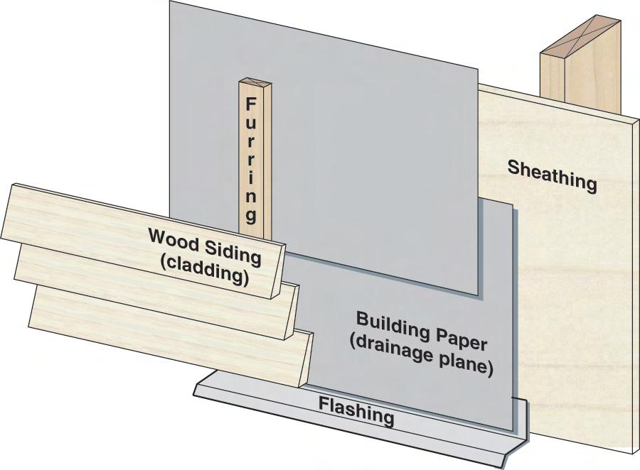
9 Figure 4: Failed water drop test of a housewrap For all sidings (except vinyl) it is recommended that they be installed over some form of drainage matt or furring strips in order deal with the problems of water retention and potential surfactant contamination. This spaces the siding off of the housewrap to prevent surfactant contamination, increases drainage, and often increases drying by ventilation as well. Furring strips are a more traditional method of moving the siding off of the back up wall construction, however from past experience both methods have been very successful at managing the moisture problems with board sidings and house wraps. Figure 5: Drainage matt installed behind wood shingles Hard Coat Stucco, Thin Brick, and Manufacured Stone Veneer In the case of stucco, thin brick, and manufactured stone veneer, renderings tend to bond to all plastic housewraps and some building papers. This reduces or eliminates the ability of the assembly to drain. Page 9 of 26 BSP-020: for Residential Buildings


10 Figure 6: Stucco renderings bonded to house wrap Stucco, thin brick, and manufactured stone veneer systems should always be installed over two layers of building paper, or one layer of building paper over a layer of house wrap. The first layer of building paper acts as a bond break, leaving the second layer to continue to perform its intended function of a drainage plane. Other drainage plane concerns with stucco can be created when there is a change in the back up wall construction. In Florida it is common for the main floor of the house construction to be concrete block while the top floor is wood frame. Stucco is commonly installed directly onto the concrete block with no building paper installed behind the stucco. This barrier cladding approach can be used successfully due to the capacity of concrete block to absorb water and dry out under more favorable conditions. The problem occurs at the transition between the drained and barrier cladding approach. Standard stucco installation practices have created a reverse flashing at this location.the stucco control joint is traditionally installed over top of the building paper. This directs the water towards the interior at the top of the masonry block. Page 10 of 26 BSP-020: for Residential Buildings


11 Figure 7: Control joint over top of building paper (not recommended) This problem can be corrected by using a weep screed for the control joint and ensuring that the building paper drainage plane is installed in a shingle lap fashion over the screed. In addition, the transition joint should also be protected by a strip of waterproof self adhered membrane. The membrane flashing will prevent moisture that builds up at the base of the stucco just above the screed from being driven to interior at this location. Figure 8: Weep screed used as a control joint with building paper shingle lapped over top of the flange Flashings Flashings are used as a means to direct water back out to the exterior and away from the various construction assemblies. They are fundamental to any water management system. Flashing can be created using any number of materials or products such as metal, plastics, and flexible membranes. The application is to provide a means to direct water from the drainage plane of the assembly, through the cladding and out to the exterior. When installed properly, they provide superb protection from water penetration into building assemblies, when installed poorly; they can become water injection devices into building assemblies. Installation Concerns Flashings should all be sloped in the direction of drainage. This may seem like a simple enough concept to incorporate into the design, however, surprisingly the most fundamental failure mechanism for a flashing installation is through installing the flashing with a reverse slope. With reversed sloped flashings water is held by the flashing and drains to the side and off the ends of the flashing back into the assembly. This can also hold water up against claddings and other materials, potentially reducing the service life of the products. All flashings should be installed with a positive slope to drain to the exterior. Page 11 of 26 BSP-020: for Residential Buildings


12 Figure 9: Basic flashing principles reverse sloped flashing Figure 10: Reverse sloped flashing A second common problem with flashing installations is not properly integrating the flashing into the drainage plane of the wall assembly. Flashings should be shingle lapped into the drainage plane of the wall assembly. For head flashings, if the top edge is left exposed, water can potentially drain behind the flashing and into the assembly. Depending on the location, taping or sealing the top edge of the flashing with a flexible membrane may be adequate, though it is always more reliable if the flashing is shingle lapped into the drainage plane. Special Flashing Details Flashings are used in many different ways and different locations. Most common are through wall flashings at floor separations and head flashing above windows. There are also some specialty type flashings that should be incorporated into the design of the water management system. Step flashing/roof Wall connection Step flashing are a very common and long used approach to integrate the drainage from the wall assembly above a sloped roof to the shingle installation used on most sloped roof applications. The step flashing weaves the drainage plane from the wall into the laps of the roof shingles. Page 12 of 26 BSP-020: for Residential Buildings

13 Traditionally, the step flashing is installed by the roofing contractor as a method to terminate the roof installation. This has created problems in the past, when the step flashing is not properly integrated into the drainage plane of the wall. It is important that the wall drainage plane lap over top of the step flashing to direct water in the wall assembly out onto the roof shingles. With siding and stucco installations, this can be easily accomplished. Brick/stone veneer assemblies require more specific details. With older mass masonry wall construction, the step flashing was regletted into the exterior face of the masonry assembly. This prevented water from roof drainage from penetrating into the wall assembly; however it did not provide a means for water, which had leaked past the exterior face of the masonry, to be directed back onto the roof. This worked adequately in mass reservoir type construction due to the face of the masonry being the primary drainage plane and the ability of the wall construction to manage a certain amount of water leakage and absorption. This detail however does not function well for veneer applications as masonry veneers do not follow the same rain water management principles. The drainage plane in a brick/stone veneer installation is behind the masonry. With the traditional step flashing installed to the exterior face, there is no method to direct the water back out onto the roof and therefore the water leaks into the construction below. For brick/stone veneer installations a through wall flashing must also be incorporated into the design in addition to the step flashing. One method is to create complicated stepped down through wall flashings above the roof to wall intersection. This requires meticulous folding of sheet metal or other flashing material to be able to follow the step down nature of the masonry veneer. An alternate approach is to use a flexible membrane flashing installed from the drainage plane of the wall onto the roof deck below the masonry to water proof the joint between the wall and the roof assembly. The masonry above can either be installed directly on top of this (for small masonry loads) or supported by a steel angle fastened back to the structure (for larger masonry loads). The step flashing can still be installed to the exterior face of the masonry; however the step flashing installation is now more of an aesthetic termination for the masonry than a critical water management component. Kick out flashing Kick out flashings are used at the bottom edge of a roof to wall intersection, where the roof ends and the wall continues on. They are used to direct the water out from below the cladding at the step flashing plane and away from the wall. This prevents water from draining off the roof and into the wall system below. It also helps aesthetically, as it prevents unsightly stains on the wall cladding from roof drainage. Figure 11: Kick out flashing conceptual design Page 13 of 26 BSP-020: for Residential Buildings


14 Figure 12: Kick out flashing installations In order for the kick out flashing to be effective, the bottom seam must be properly sealed or folded to ensure that water does not leak through the joint. Improperly folded or sealed kick out flashings will cause a high water concentration to be poured behind the cladding. Figure 13: Poorly folded kick out flashing Kick out flashing are also required with brick/stone veneer installations. The flashing must extend from the drainage plane of the wall behind the veneer out through the front face of the masonry. The geometry of the kick out flashing will depend on the shape of the veneer cladding in order to be integrated into the masonry pattern; however the same principles will still apply. Other Penetrations Often miscellaneous penetrations such as mechanical penetrations, balcony railings, and or porch framing attachment are improperly integrated into the design and construction of the water management system of the building. Being less common than many other details they can be overlooked or improperly sequenced. Page 14 of 26 BSP-020: for Residential Buildings


15 Figure 14: Electrical utility installed after water management system Figure 15: Panel installed before installation of the drainage plane Mechanical penetrations, including exterior lighting, electrical boxes, dryer vents, gas utility penetrations etc. need to be properly flashed and integrated into the design of the water management system. This can often be achieved through the use of self adhered membrane flashings. Some products are also available that provide flanges that can be sealed and shingled lapped into the drainage plane permitting these penetrations to be more easily incorporated into the water management system. Page 15 of 26 BSP-020: for Residential Buildings


16 Figure 16: Membrane flashed exhaust vent Figure 17: Flanged electrical box Saddle flashings are used in locations where building elements penetrate through the cladding and are attached to the back up wall construction. This occurs at such places as balcony railings, porch framing attachments, retaining walls, and some mechanical penetrations. Figure 18: Saddle flashing conceptual design Page 16 of 26 BSP-020: for Residential Buildings

17 Windows Probably the most consistent form of building enclosure failure in most climate zones is through water penetration from window installations. Windows are a key part to almost every building, as they improve the indoor environmental quality through day lighting, views, and in some cases ventilation. Yet they are also one of the most difficult components of the building enclosure to incorporate into the water management system. Leaks from windows have existed as long as windows have existed. Water not only leaked through the windows themselves, but also around the windows at the interface between the rough opening and the window frame. In many older solid masonry buildings this was not a problem due to the capacity of the construction to absorb moisture and dry out under more favorable conditions. As the construction industry changed, materials and assemblies began to be used that had less of a capacity to manage moisture. The absorption capacity and the drying potential of assemblies were significantly reduced. This led to serious building enclosure failures related to window leakage. Figure 19: Water intrusion through the window frame Installation Concerns Risks associated with window leaks are affected by various characteristics from the climate in which the window is installed, to the materials used, to the skill and attitude of the person doing the installation. Understanding these factors including the limitations and critical aspects of the installation is important in deciding the appropriate installation technique to use. In general there are two basic window installation strategies: a barrier approach or a drained approach. The barrier approach works under the preconception that the installation will keep all the water out and is the approach used by much of the industry. In this approach, the window is sealed on all four sides in an attempt to create a perfect barrier against water infiltration. Experience has shown that most window installations do not have the ability to perform as a perfect barrier for Page 17 of 26 BSP-020: for Residential Buildings

18 the life of the window installation. Due to this, barrier systems, while a form of water management, are not generally recommended and should only be considered for use in certain assemblies such as mass wall assemblies. Drained systems work under the preconception that some water will leak through the window at some point in time, and provisions are made to direct the water back out to the exterior. This approach has been shown to be an effective method of water management, though care must still be taken in the design and application of the system. Nailing Flange Most residential windows on the market are designed with a nailing flange to help with the installation of the window. The flange is intended to make consistently lining up the window in the same location in the rough opening easier. The flange, however, is often not structural and proper shimming and blocking of the window is required. This nailing flange has some advantages and some disadvantages associated with it. While it does make the installation easier, the water management strategies must be carefully considered. The nailing flange provided a good opportunity to be used as a part of the drainage plane of the wall assembly for both barrier as well as drained window installations. The flat flange installed (for the most part) at the plane of the exterior sheathing seemed to be a perfect match to integrate the window into the moisture management system of the home. It does work very effectively, as long as the flange is continuous around the entire window perimeter and integrity of the flange is maintained. The nailing flange is usually a thin PVC or metal fin that is part of the frame extrusion and generally not very strong. These flanges can be damaged, bent or broken during the delivery or installation of the window system into the wall assembly, or may not be continuous around the window depending on the assembly at the corner joints of the frame. Damaged and broken nailing fins can lead to fundamental failures in the integrity of the drainage plane of the wall assembly as membrane tapes and building papers/housewraps no longer have adequate area of material to adhere to or cover over the flange. Figure 20: Discontinuity of the nailing flange at the corners Page 18 of 26 BSP-020: for Residential Buildings


19 Figure 21: Bent and damaged nailing flanges being delivered to site Figure 22: Cracked nailing flange at corner connection As long as the nailing flange is continuous and undamaged it can be effectively integrated into the moisture management of the wall assembly. Self adhered membranes are often used to integrate the nailing flange into the drainage plane of the water management system of the wall assembly. Self adhered membranes used to seal to the nailing flange must be installed, as with other water management concepts, in a shingle lap fashion to prevent reverse laps that can create paths for water intrusion. While this concept is generally understood, repetitive installations and requirements to complete the installations in a timely manner, has led to poor installations and problems with installation. Page 19 of 26 BSP-020: for Residential Buildings

20 Figure 23: Reverse lap of self adhered membrane at window sill in a barrier installation Often, due to the different trades on the site, or the sequencing of materials being delivered to the site, the windows may be installed before or after the installation of the drainage plane material. In either case, provisions must be made to allow the window to be integrated into the drainage plane of the assembly. It is important to ensure that the building paper or housewrap laps over the flange and self adhered membrane at the head of the window. If the building paper/housewrap is installed prior to the window, then a flap of paper at the head should be turned up during the installation of the window, then the flap can be dropped back down over the top of the flange. Using self adhered membrane flashings and other tapes to seal the nailing flange at the head of the window, while reducing the risk of water intrusion, still create a reverse lap and must remain completely sealed for the service life of the installation in order to be effective. Pan Flashing The installation of a pan flashing at the sill of the rough opening is critical to the design of drained window installations. They are used to protect the framing of the rough opening from moisture damage and to help direct any water back out to the exterior. These pan flashings can be created out of numerous different types of materials, from preformed plastics, membrane flashings, and metal. Ideally, the pan flashing would be sloped to the exterior. This can be achieved through the use of a section of board siding laid flat under the pan flashing. In cases where positive slope to drain is not practical, then a back dam should be installed to prevent water from draining back to the interior. Page 20 of 26 BSP-020: for Residential Buildings
21 Figure 24: Sill and backdam options The condition of the rough opening can affect the performance of the drainage of the pan flashing. The exterior sheathing must not extend higher than the sill framing. In this situation, even with a perfectly installed pan flashing, the drainage of the system will be compromised. Page 21 of 26 BSP-020: for Residential Buildings


22 Figure 25: Drainage blocked due to exterior sheathing above the sill framing The geometry of the sill with a back dam creates a situation where several planes of construction come together in a small area. With membrane flashings this can lead to installation problems due to the need to use a two dimensional product in a 3 dimensional application. The membranes must be folded, cut, and layered in such a way as to protect the surrounding construction. The time and care that this takes is not always done. Problems that can arise are tenting of the membrane in the corners, holes, and fishmouths. Tenting of the membranes occurs when the membrane pieces are not seated properly into the corners of the sill rough opening. The result is a curved fillet, placing the flashing in tension with a void beneath. Because of this tearing of the membrane can occur during the installation of the pan flashing, or the sharp corners of the window frame can cut or damage the reinforcing of the membrane leading to failures in the integrity of the pan flashing. Figure 26: Tenting of the membrane pan flashing in the corner Page 22 of 26 BSP-020: for Residential Buildings


23 Figure 27: Torn membrane pan flashing Figure 28: Window corner cutting into improperly seated pan flashing Rushed installations also lead to problems with poor membrane installations and fishmouths. Fishmouths act as a funnel to direct water into the construction. Page 23 of 26 BSP-020: for Residential Buildings

24 Figure 29: "Fishmouthing" of the membrane As a means to correct some of these concerns, other products available on the market such as moldable membrane flashings and preformed plastics can be used for the installation of the pan flashing. Moldable membrane flashings allow for a single piece of membrane to be installed at the corner of the sill as the membrane can stretch to fan out and curve around corners. Preformed plastic pan flashings have also been developed to address this problem of time consuming and finicky work of creating pan flashings with membranes. The preformed plastic sections usually have integrated backdams as well. With these products the jambs and sill joint between the two pieces must still be sealed with membrane to prevent water intrusion below the pan flashing. Figure 30: Moldable membrane and preformed plastic pan flashings Page 24 of 26 BSP-020: for Residential Buildings


25 Figure 31: Weather seal gasket used as a backdam Figure 32: Single piece moldable membrane pan flashing with backdam Furred Out Windows Many architectural designs attempt to push the window frame further to the exterior of the wall assembly for aesthetic reasons. While it is possible to design the water management system to function adequately with this type of window installation, the difficulties associated with trying to move the window further to the exterior generally do not make this a recommended approach. The furring strips move the window out of the drainage plane of the wall assembly. This adds more three dimensional complexity to the window, flashing, and housewrap installation details. Clearance requirements between adjoining assemblies can also become an issue. Most sheet good products become difficult to install in locations where there are multiple changes in plane in a relatively small location, often leading to poor installations and discontinuities in the drainage plane. Page 25 of 26 BSP-020: for Residential Buildings

26 Figure 33: Window furred out from the drainage plane (not recommended) Conclusion Many of the details are still fairly new to many builders, and there is a learning curve associated with the proper design, integration, and installation of these water management concepts. As these details become more common in the design of the water management systems for homes, these details will become part of the standard repertoire for contractors. To prevent bad habits from forming, it is important at this time to work towards ensuring that critical areas of installation are recognized and that proper installation methods are understood and used. Page 26 of 26 BSP-020: for Residential Buildings