Submittal Review A
|
|
|
- Piers Fitzgerald
- 5 years ago
- Views:
Transcription
1 Submittal Review TO: Pavilion Construction DATE: JOB NO.: 1484P 4700 SW Macadam Ave Suite 200 ATTENTION: Riley Tobin Portland, OR RE: BSD Sunset High School Concession Stand/Interior Renovations Package 1 Submittal: Non Structural Metal Framing Approved Approved As Noted Revise as Noted/Resubmit Rejected/Resubmit As Specified No Action Required Submittal Not Requested/Returned Without Review Approval is for conformance with information given and the design concept expressed in the Contract Documents. Contractor is responsible for quantities and dimensions to be confirmed and correlated; for fabrication process; for means methods, techniques, sequences and procedures of construction; for coordination of the Work; and for all safety aspects of performing the Work. Approval does not modify the Contract Documents and approval of a specific item does not indicate approval of an assembly of which the item is a component. Specification Section Title Notation A Product Data: 1 5/8 Metal Studs Approved A Product Data: Metal Stud Track Approved A Product Data: 7/8 Metal Channel Furring Not Submitted. Resubmit A Product Data: Relating to and Sized by Qualified Engineer per Delegated Design Submittal Not Submitted. Resubmit B Delegated Design Submittal Not Submitted. Resubmit. Summary Comments: 1. The specifications referenced in this submittal are dated 05/15/15. Please use the current Permit Rev 4 June 16, 2015 specifications as released in ASI #1. 2. Please submit delegated design portion of this submittal. 3. Per 2.3B, submit product data for 7/8 hat channel furring SW 5 th Ave. // Suite 1100 // Portland // OR // P: //


2 Sunset High School NW Cornell Rd. Portland, OR To: Attn: BLRB ARCHITECTS, P.S. RICHARD HIGGINS 1001 SW 5TH AVE., SUITE 1100 PORTLAND, OR Date: Contact Phone: Contact 07/13/ CC d: SUBMITTAL TRANSMITTAL FOR APPROVAL Submittal #: 27 Rev.#: 0 In Accordance with Specification Section #: This is a submittal for Non Structural Metal Framing items per the table below as reviewed and noted by Pavilion Construction NW, LLC, and provided by MCG COMMERCIAL. Please provide a response to this submittal by 07/23/2015. Pavilion Status: Sent/Submitted Notes: Submitted By: Address: Riley Tobin rtobin@pavilionconstruction.com Phone: Fax: (503) (503) SUBMITTAL RESPONSE Architect s Response Proceed Proceed, as noted Revise and Resubmit Material Return without Review Schedule Tracking Date Date Date Date Received from Sub/Sup Requested to be returned Returned from Architect Returned to Sup/Sup 07/09/ /23/2015 Comments: PAVILION CONSTR JCTION LLC o APPROVEDAS SUBMITTEO o OISAPPROVEO, PlIASE SUBMIT COPlES ory: _APPRDVEOAS NOTEO o 07/13/15 DATED: _ F()R THE RECORD _ 06/23/15 Riley Tobin This submittal has been reviewed for general "onformil."'.ce with ttle contract documents. Tn's review does not reuevs the supplier of responsibility for erro~, omissions or any dtviition tram the requirements of the ",.....r?c! :!vr:umems. Mike Harmel Pavilion Construction NW, LLC 4700 SW Macadam Ave. Portland, OR Phone: (503) Fax: (503) Page 1 of 1
3 Sunset High School - Title IX and Upgrades Beaverton School District No. 48 BLRB Project No.: 14.84P Permit Set May 15, 2015 SECTION NON-STRUCTURAL METAL FRAMING PART 1 - GENERAL 1.1 RELATED DOCUMENTS A. Drawings and general provisions of the Contract, including General and Supplementary Conditions and Division 01 Specification Sections, apply to this Section. 1.2 SUMMARY A. Section Includes: 1. Non-load-bearing steel framing members. 2. Grid suspension systems for gypsum board ceilings. B. Related Sections include the following: 1. Division 07 Section "Thermal Insulation" for insulation installed with Z-shaped furring members. 2. Division 09 Section Gypsum Board for installation of gypsum of gypsum board. 1.3 SUBMITTALS A. Product Data: For each type of product indicated. 1.4 QUALITY ASSURANCE A. Fire-Test-Response Characteristics: For fire-resistance-rated assemblies that incorporate non-load-bearing steel framing, provide materials and construction identical to those tested in assembly indicated according to ASTM E 119 by an independent testing agency. B. STC-Rated Assemblies: For STC-rated assemblies, provide materials and construction identical to those tested in assembly indicated according to ASTM E 90 and classified according to ASTM E 413 by an independent testing agency. C. Systems Design: Design all systems and components of non-structural metal framing in conformance with the guidelines of the Gypsum Construction Handbook and SSMA Product Technical Information. 1. All systems and components not in conformance with the guidelines of the Gypsum Construction handbook and the SSMA Product Technical Information shall be designed by a Structural Engineer licensed in the state in which the project is located. BLRB Architects - Portland, Oregon NON-STRUCTURAL METAL FRAMING
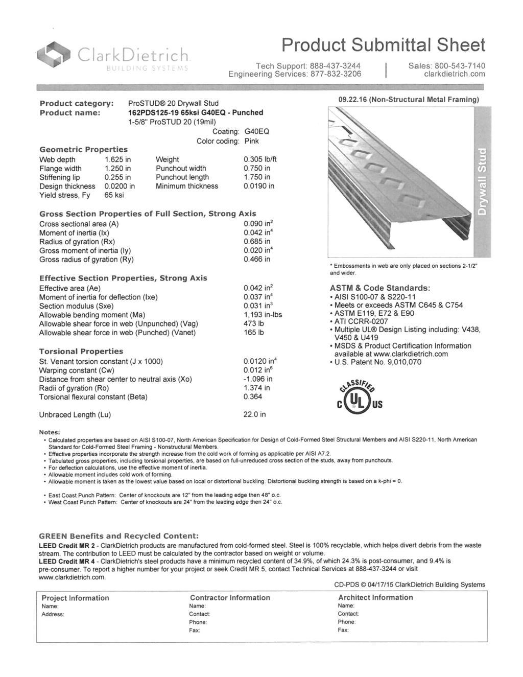
4 Sunset High School - Title IX and Upgrades Beaverton School District No. 48 BLRB Project No.: 14.84P Permit Set May 15, 2015 PART 2 - PRODUCTS 2.1 NON-LOAD-BEARING STEEL FRAMING, GENERAL A. Framing Members, General: Comply with ASTM C 754 for conditions indicated. Refer to Structural General Notes and Drawings for additional requirements. 1. Steel Sheet Components: Comply with ASTM C 645 requirements for metal, unless otherwise indicated. 2. Protective Coating: ASTM A 653/A 653M, G60, hot-dip galvanized, unless otherwise indicated. 2.2 SUSPENSION SYSTEM COMPONENTS A. Tie Wire: ASTM A 641/A 641M, Class 1 zinc coating, soft temper, inch-diameter wire, or double strand of inch-diameter wire. B. Hanger Attachments to Concrete: 1. Anchors: Fabricated from corrosion-resistant materials with holes or loops for attaching wire hangers and capable of sustaining, without failure, a load equal to 5 times that imposed by construction as determined by testing according to ASTM E 488 by an independent testing agency. a. Type: Cast-in-place anchor, designed for attachment to concrete forms or postinstalled, expansion anchor. 2. Powder-Actuated Fasteners: Do not attach hangers to underside of concrete slabs with powder-actuated fasteners.. C. Wire Hangers: ASTM A 641/A 641M, Class 1 zinc coating, soft temper, inch diameter. D. Flat Hangers: Steel sheet, 1 by 3/16 inch by length indicated. E. Carrying Channels: Cold-rolled, commercial-steel sheet with a base-metal thickness of inch and minimum 1/2-inch-wide flanges. 1. Depth: 1-1/2 inches. F. Furring Channels (Furring Members): 1. Cold-Rolled Channels: inch bare-steel thickness, with minimum 1/2-inch-wide flanges, 3/4 inch deep. 2. Steel Studs: ASTM C 645. a. Minimum Base-Metal Thickness: inch. b. Depth: As indicated on Drawings. 3. Hat-Shaped, Rigid Furring Channels: ASTM C 645, 7/8 inch deep. a. Minimum Base Metal Thickness: inch. 4. Resilient Furring Channels: 1/2-inch-deep members designed to reduce sound transmission. a. Configuration: Asymmetrical. BLRB Architects - Portland, Oregon NON-STRUCTURAL METAL FRAMING
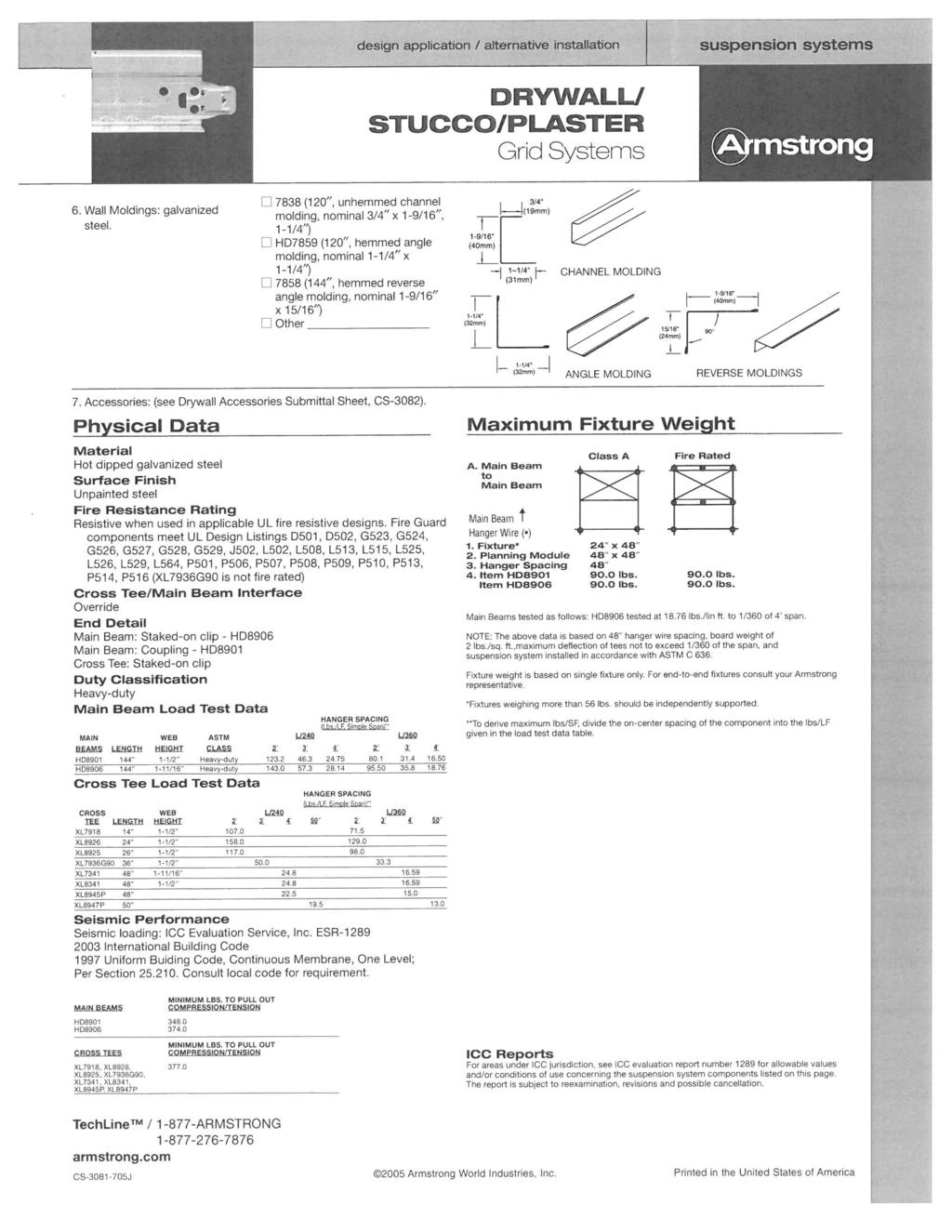
5 Sunset High School - Title IX and Upgrades Beaverton School District No. 48 BLRB Project No.: 14.84P Permit Set May 15, 2015 G. Grid Suspension System for Gypsum Board Ceilings: ASTM C 645, direct-hung system composed of main beams and cross-furring members that interlock. 1. Available Products: Subject to compliance with requirements, products that may be incorporated into the Work include, but are not limited to, the following: a. Armstrong World Industries, Inc.; Drywall Grid Systems. b. Rockfon; Chicago Metallic 640. c. USG Corporation; Drywall Suspension Systems. d. Or approved. H. Metal Edge Moldings and Trim: Roll-formed, sheet-metal edge moldings and trim of type and profile indicated. 2.3 STEEL FRAMING FOR FRAMED ASSEMBLIES A. Flat Strap and Backing Plate: Steel sheet for blocking and bracing in length and width indicated. 1. Minimum Base-Metal Thickness: inch(20-gauge) thickness B. Hat-Shaped, Rigid Furring Channels: ASTM C Minimum Base Metal Thickness: inch(25-gauge). 2. Depth: 7/8 inch. C. Resilient Furring Channels: 1/2-inch-deep, steel sheet members designed to reduce sound transmission. 1. Configuration: Asymmetrical or Hat shaped. D. Cold-Rolled Furring Channels: inch bare-steel thickness, with minimum 1/2-inch-wide flanges. 1. Depth: As indicated on Drawings. 2. Furring Brackets: Adjustable, corrugated-edge type of steel sheet with minimum bare-steel thickness of inch. 3. Tie Wire: ASTM A 641/A 641M, Class 1 zinc coating, soft temper, inch-diameter wire, or double strand of inch-diameter wire. E. Metal Wall Backing for fastener backing at wall locations to be clad with wainscot, decorative panels, veneer wall paneling, etc. 1. Metal Backing Thickness: 20 Gauge by width required to provide fasten retention for wall paneling. 2.4 AUXILIARY MATERIALS A. General: Provide auxiliary materials that comply with referenced installation standards. 1. Fasteners for Metal Framing: Of type, material, size, corrosion resistance, holding power, and other properties required to fasten steel members to substrates. BLRB Architects - Portland, Oregon NON-STRUCTURAL METAL FRAMING
6 Sunset High School - Title IX and Upgrades Beaverton School District No. 48 BLRB Project No.: 14.84P Permit Set May 15, 2015 PART 3 - EXECUTION 3.1 EXAMINATION A. Examine areas and substrates, with Installer present, and including welded hollow-metal frames, cast-in anchors, and structural framing, for compliance with requirements and other conditions affecting performance. 1. Proceed with installation only after unsatisfactory conditions have been corrected. 3.2 PREPARATION A. Suspended Assemblies: Coordinate installation of suspension systems with installation of overhead structure to ensure that inserts and other provisions for anchorages to building structure have been installed to receive hangers at spacing required to support the Work and that hangers will develop their full strength. 1. Furnish concrete inserts and other devices indicated to other trades for installation in advance of time needed for coordination and construction. 3.3 INSTALLATION, GENERAL A. Installation Standard: ASTM C 754, except comply with framing sizes and spacing indicated. 1. Gypsum Board Assemblies: Also comply with requirements in ASTM C 840 that apply to framing installation. B. Install supplementary framing, and blocking to support fixtures, equipment services, heavy trim, grab bars, toilet accessories, furnishings, or similar construction. 1. Additional Blocking: Required at location(s) of equipment that is indicated on Contract Drawings as: Owner-furnished Owner-installed; Owner Furnished Contractor Installed; or (NIC) "Not in Contract." C. Install bracing at terminations in assemblies. D. Do not bridge building control and expansion joints with non-load-bearing steel framing members. Frame both sides of joints independently. E. Isolation: Isolate steel framing from building structure to prevent transfer of loading imposed by structural movement, at locations as follows; where edges of suspended ceilings abut building structure horizontally at ceiling perimeters or penetration of structural elements, and where non-bearing partition and wall framing abuts overhead structure. Provide slip or cushioned type joints as detailed to attain lateral support and avoid axial loading 3.4 INSTALLING SUSPENSION SYSTEMS A. Installation Standard: NWCB Suspension Systems for Acoustical Lay-in Ceilings Seismic Design Categories D, E & F. B. Install suspension system components in sizes and spacings indicated on Drawings, but not less than those required by referenced installation standards for assembly types and other assembly components indicated. BLRB Architects - Portland, Oregon NON-STRUCTURAL METAL FRAMING
7 Sunset High School - Title IX and Upgrades Beaverton School District No. 48 BLRB Project No.: 14.84P Permit Set May 15, 2015 C. Isolate suspension systems from building structure where they abut or are penetrated by building structure to prevent transfer of loading imposed by structural movement. D. Suspend hangers from building structure as follows: 1. Install hangers plumb and free from contact with insulation or other objects within ceiling plenum that are not part of supporting structural or suspension system. a. Splay hangers only where required to miss obstructions and offset resulting horizontal forces by bracing, countersplaying, or other equally effective means. 2. Where width of ducts and other construction within ceiling plenum produces hanger spacings that interfere with locations of hangers required to support standard suspension system members, install supplemental suspension members and hangers in the form of trapezes or equivalent devices. a. Size supplemental suspension members and hangers to support ceiling loads within performance limits established by referenced installation standards. 3. Wire Hangers: Secure by looping and wire tying, either directly to structures or to inserts, eye screws, or other devices and fasteners that are secure and appropriate for substrate, and in a manner that will not cause hangers to deteriorate or otherwise fail. 4. Flat Hangers: Secure to structure, including intermediate framing members, by attaching to inserts, eye screws, or other devices and fasteners that are secure and appropriate for structure and hanger, and in a manner that will not cause hangers to deteriorate or otherwise fail. 5. Do not attach hangers to steel roof deck. 6. Do not attach hangers to permanent metal forms. Furnish cast-in-place hanger inserts that extend through forms. 7. Do not attach hangers to rolled-in hanger tabs of composite steel floor deck. 8. Do not connect or suspend steel framing from ducts, pipes, or conduit. E. Fire-Resistance-Rated Assemblies: Wire tie furring channels to supports. F. Seismic Bracing: Sway-brace suspension systems with hangers used for support. G. Grid Suspension Systems: Attach perimeter wall track or angle where grid suspension systems meet vertical surfaces. Mechanically join main beam and cross-furring members to each other and butt-cut to fit into wall track. H. Installation Tolerances: Install suspension systems that are level to within 1/8 inch in 12 feet measured lengthwise on each member that will receive finishes and transversely between parallel members that will receive finishes. 3.5 INSTALLING FRAMED ASSEMBLIES A. Where studs are installed directly against exterior masonry walls or dissimilar metals at exterior walls, install isolation strip between studs and exterior wall. B. Direct Furring: 1. Screw to wood framing. 2. Attach to concrete or masonry with stub nails, screws designed for masonry attachment, or powder-driven fasteners spaced 24 inches o.c. C. Installation Tolerance: Install each framing member so fastening surfaces vary not more than 1/8 inch from the plane formed by faces of adjacent framing. BLRB Architects - Portland, Oregon NON-STRUCTURAL METAL FRAMING
8 Sunset High School - Title IX and Upgrades Beaverton School District No. 48 BLRB Project No.: 14.84P Permit Set May 15, 2015 END OF SECTION BLRB Architects - Portland, Oregon NON-STRUCTURAL METAL FRAMING
9
10
11
12
13
14