Narrative for the 2014 AIA BIM TAP: Submission Category G Outpatient Care Pavilion
|
|
|
- Aileen Bishop
- 5 years ago
- Views:
Transcription
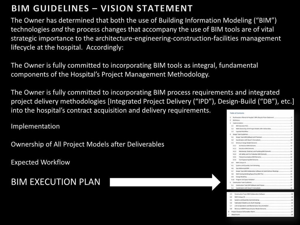
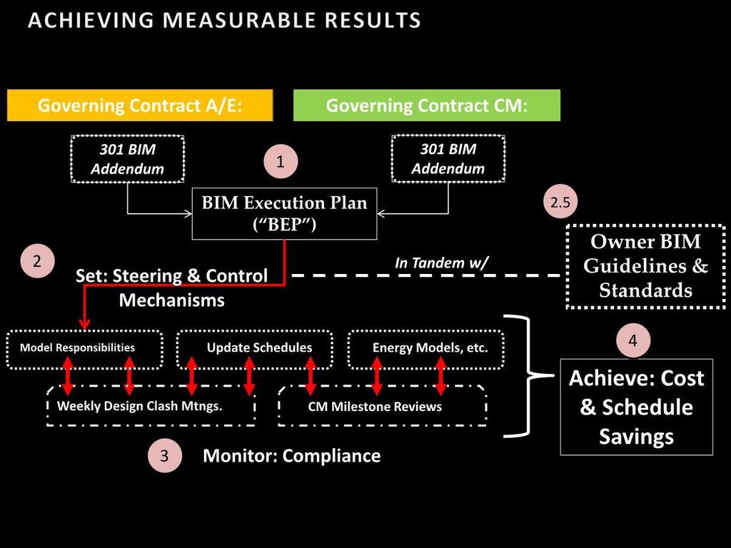
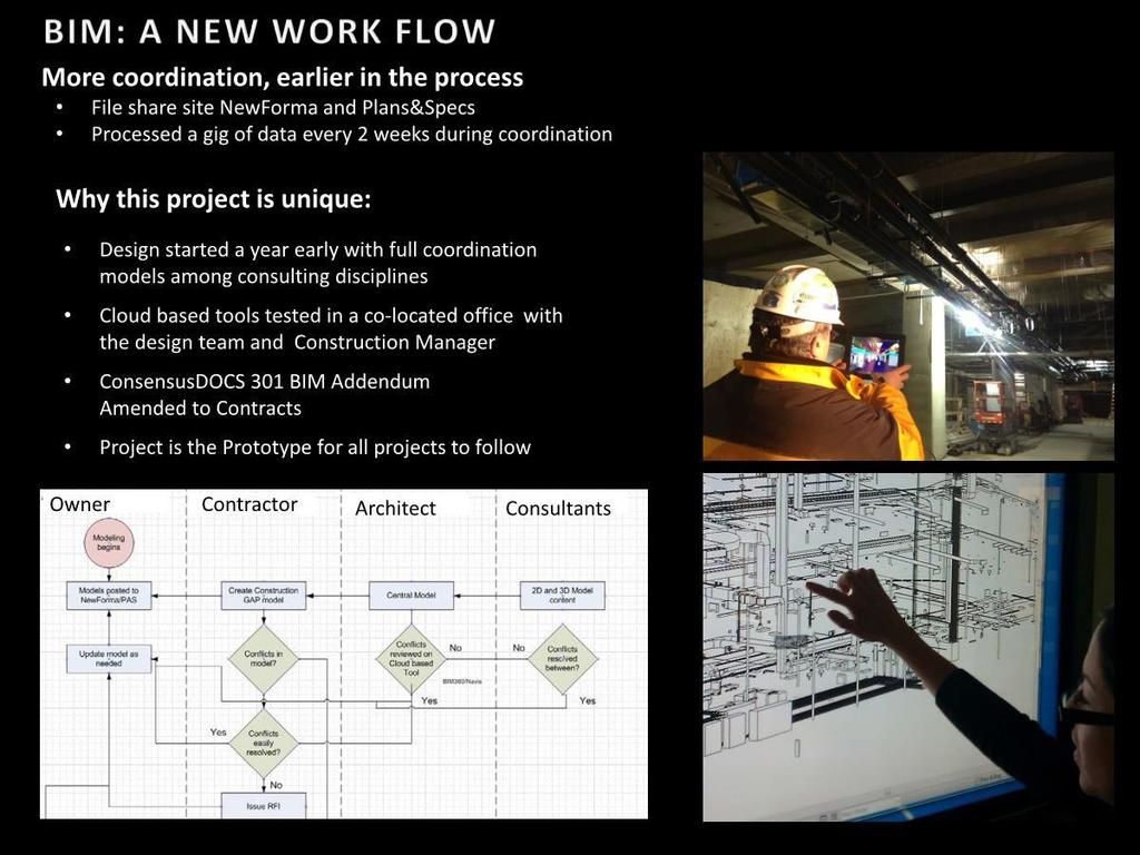
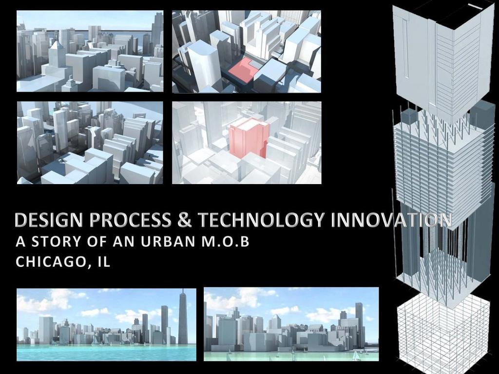
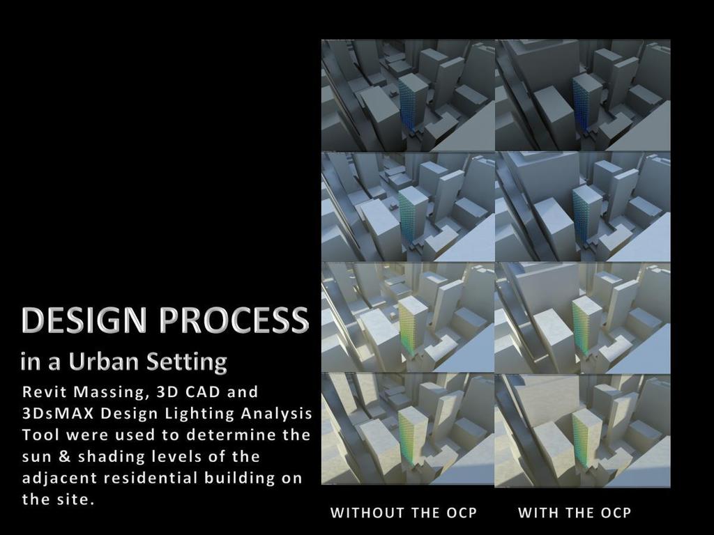
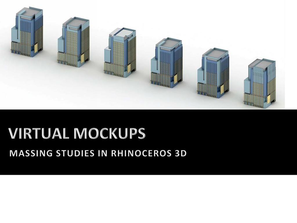
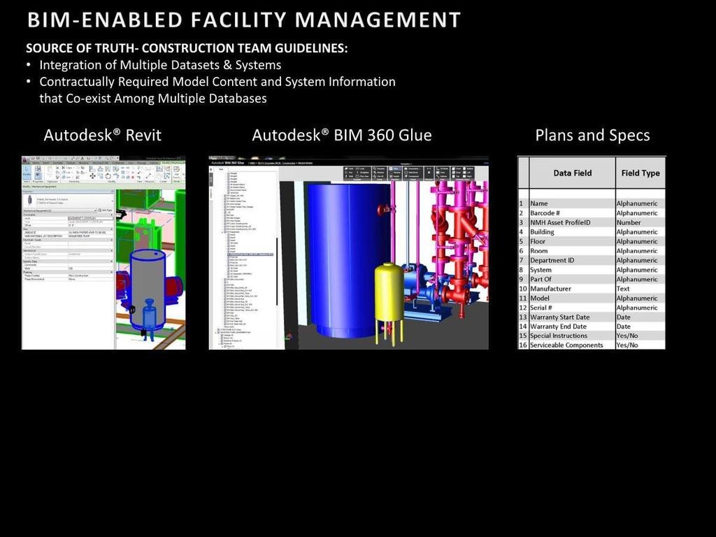
1 Narrative for the 2014 AIA BIM TAP: Submission Category G Outpatient Care Pavilion Owner s Team Pat Newman Director of Construction (key decision maker) James Mladucky Director, Facility and Construction (decision maker, value judge) Ken Kaiser Manager, Facility Renovations (FM integration director) Shrimant Jaruhar Project Manager (BIM) Facility Planning and Construction (FM Implementation specialist for campus) Design Team Randy Guillot Lead Designer (BIM integration with Design) Michael Yoshimura Project Manager (Value provider leading all things BIM for design) James Skalla Project Architect (led team with coordination of models coordination) Rand Ekman & Marya Graff LEED consultant (BIM LEED point champion) Sarah Plum Architect BIM Manager (Supervised set up of all model insertions and led design model execution) Silviu Petrea Architect BIM Manager (Supervised modeling for Mechanical. Electrical, plumbing and fire protection design models and coordination) Construction Team James Harding Executive in charge (Value judge for technology and championed procurement implementation and use of technology) Eric Engstrom Senior Project Manager (managed structural model contracts; execution) Arelias Matias Project Manager (managed MEP trade coordination and execution) Andy Gush Project Manager (managed Enclosure coordination and execution) Curtis Brown Senior Structural Superintendent (struct and ERS model review, field Supt) Bill Boscelli Senior MEP Superintendent (Field model sequencing and execution) John Jurewicz Senior BIM Integration Manager (Technology setup, implementation, BEP) Christian Torres Senior BIM Model Coordinator (GAP model support, tech go to, ID tagging) Kevin Bredeson Director of Virtual Construction (Tenant Model support and Lead) Paul Berko VDC support for tenant build out (GAP and conversion support) Work flows and Data exchanges To realize the ambitious goals outlined in the initial execution plan, Building Information modeling was deployed for the coordination of contract documents a year before the project contracts for the new building were even awarded. In the interview process, construction simulations of the site logistics were undertaken even before they were allowed to interact with the design team. The simulations were refined as the actual schedule evolved and the design was developed; exploring options and verifying the clearances needed between structure and the temporary works, such as bracing and crane placements. Site orientation, energy modeling, and concept massing were all achieved in a smart design modeling process that involved a fluid process of working with models designers and consultants. The design ideas were totally conceived in a modeling environment. In the beginning stages of the design process, no designer wants to have limitations. Of course, with the restrictions of project costs, site limitations, energy consumption and our client s desired design esthetics; Architects are restricted before the design process begins. BIM enables us to take all the restrictions within the design of a building and measure them in a very calculated and time efficient
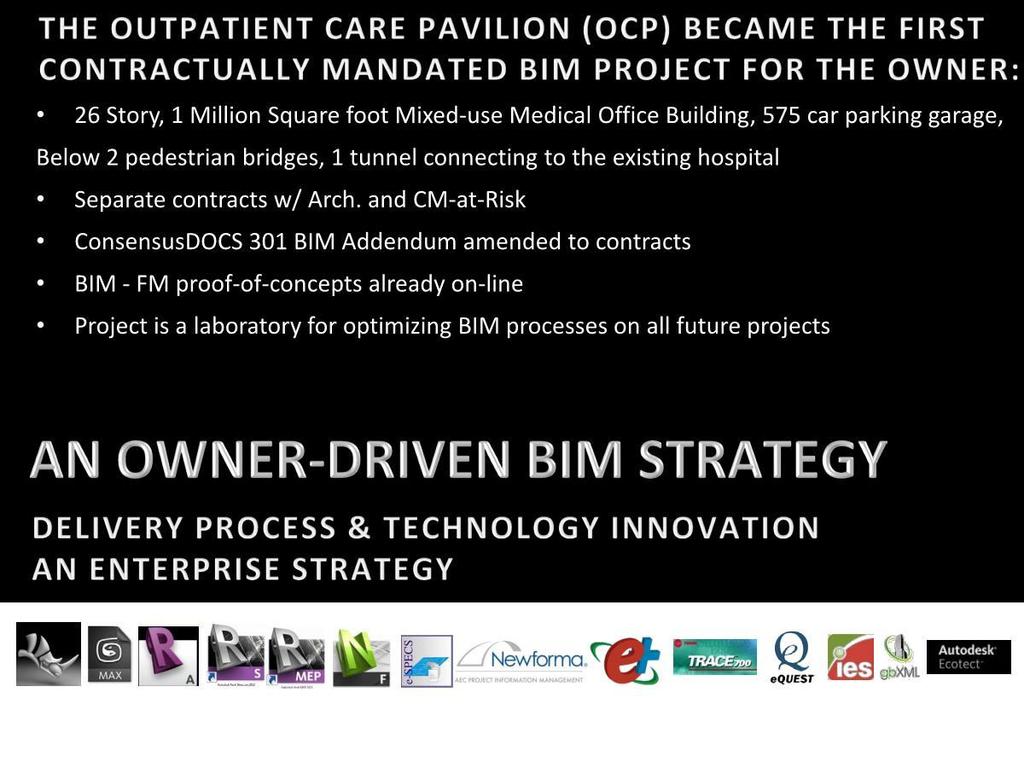
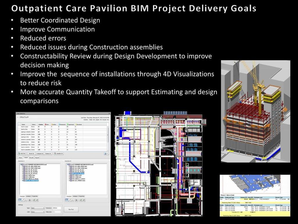
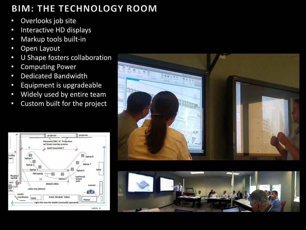
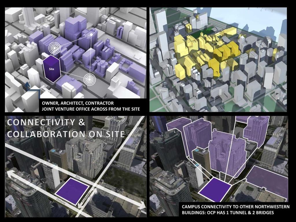
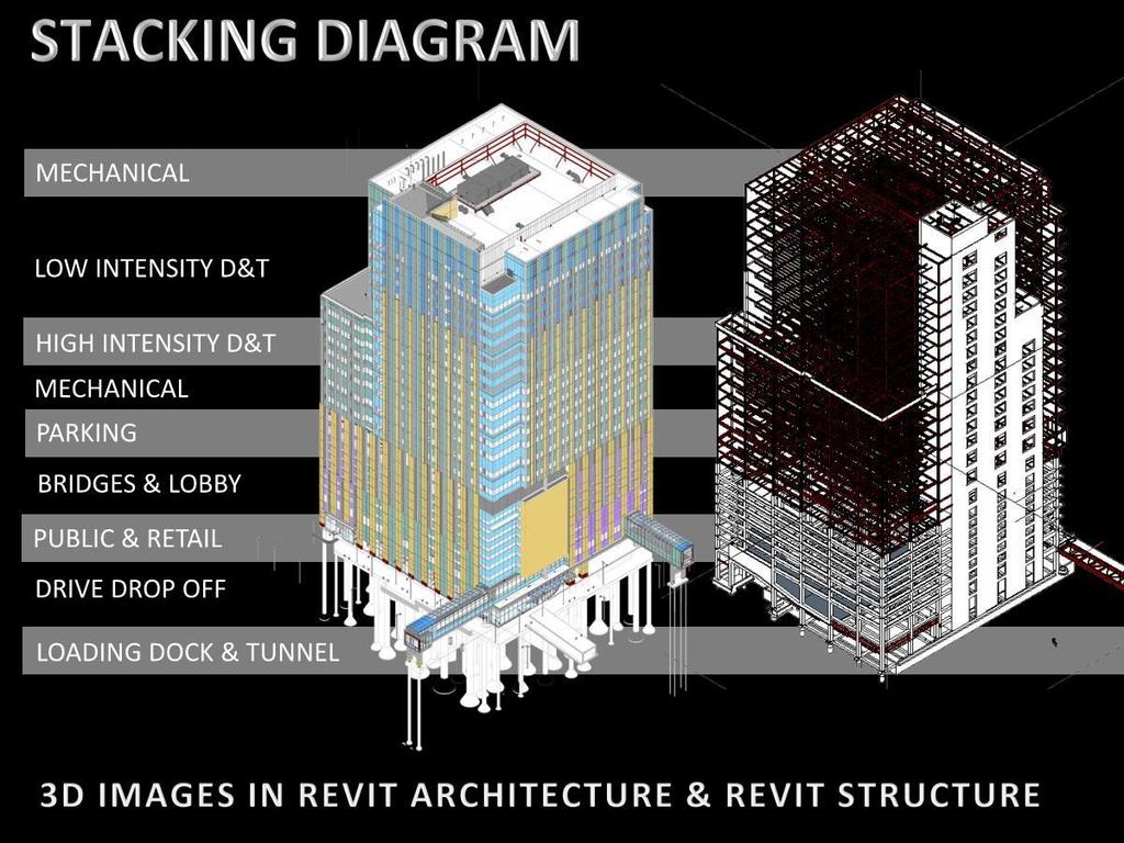
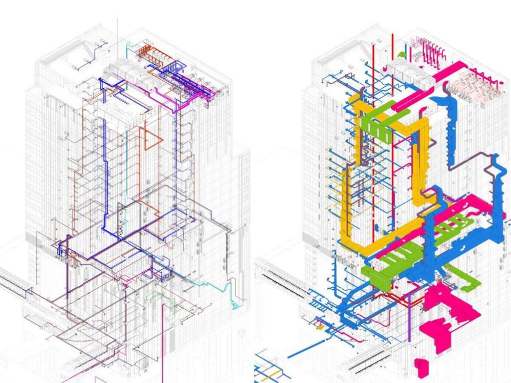
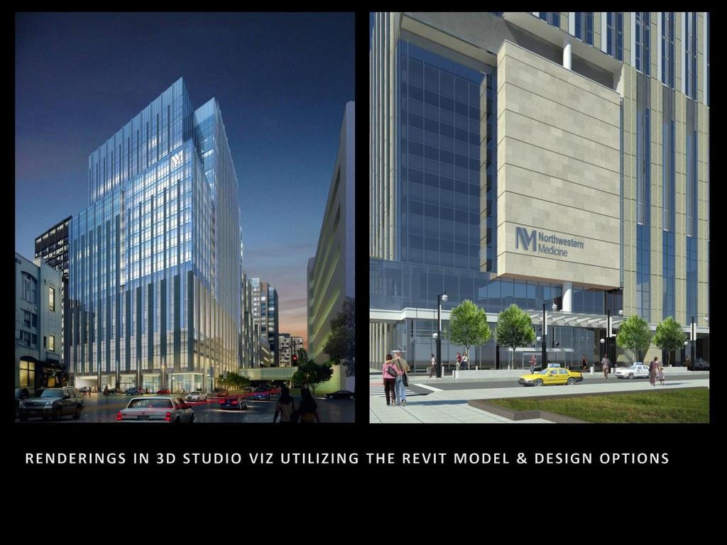
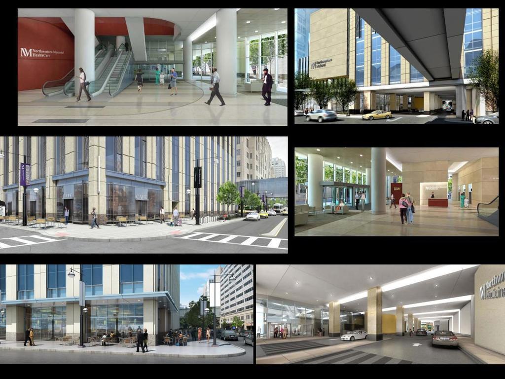
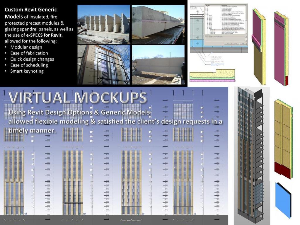
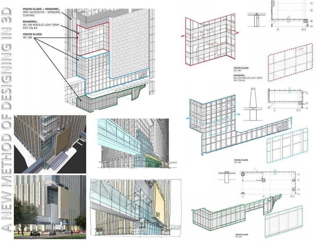
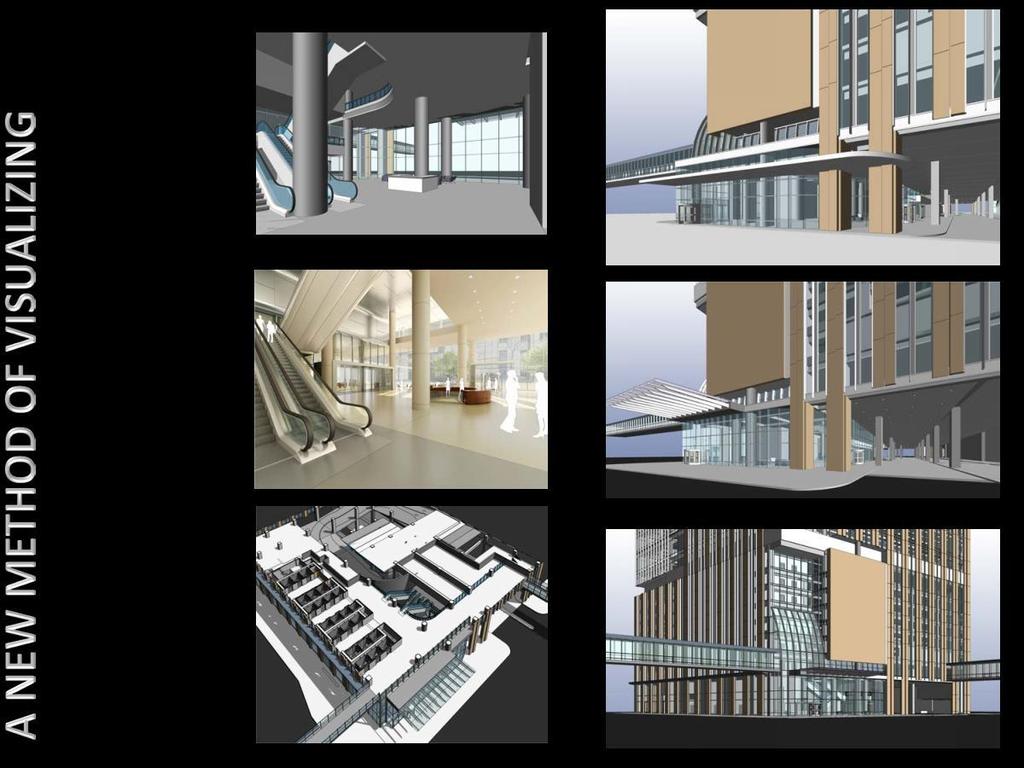
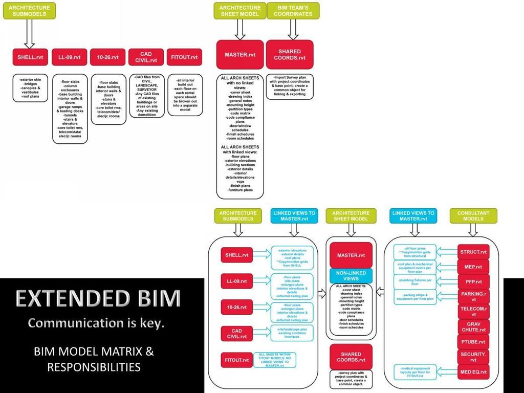
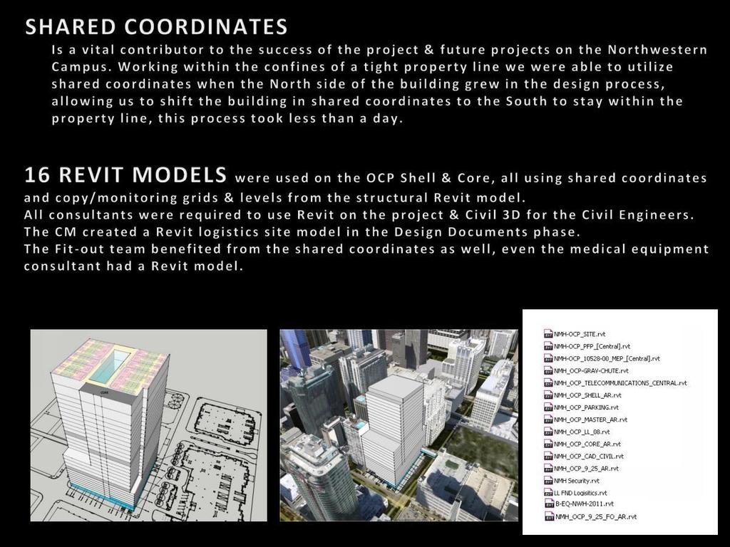
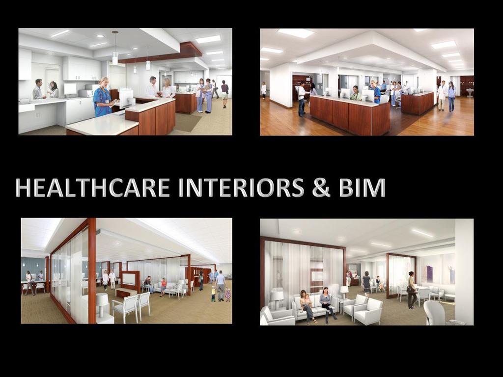
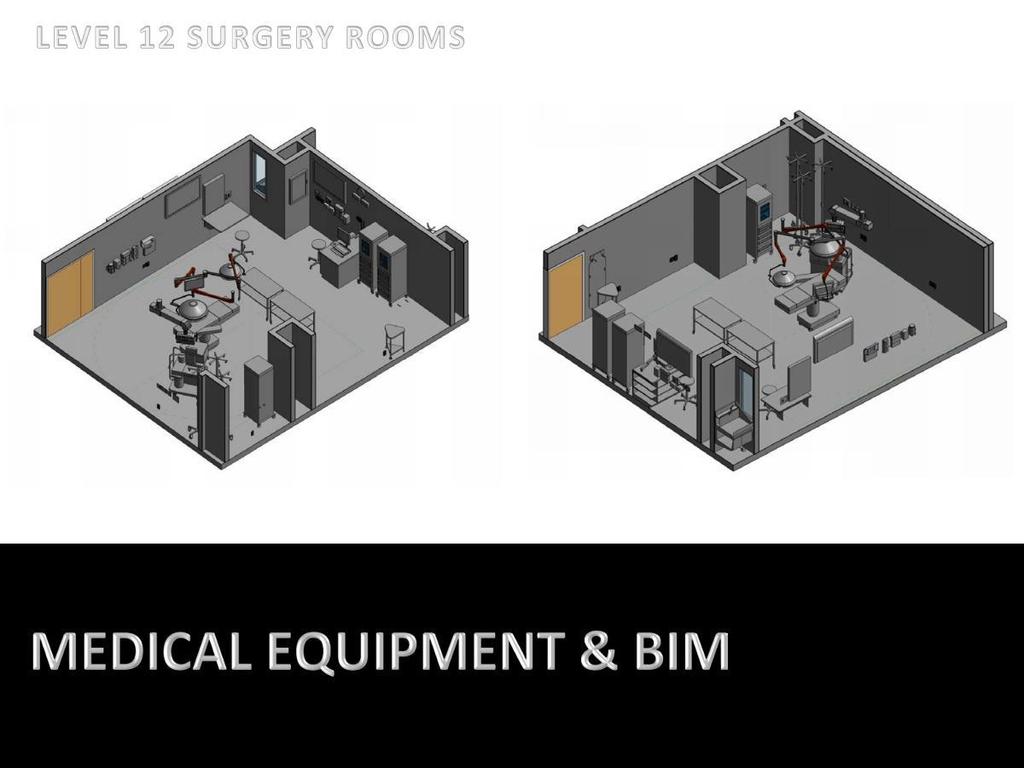
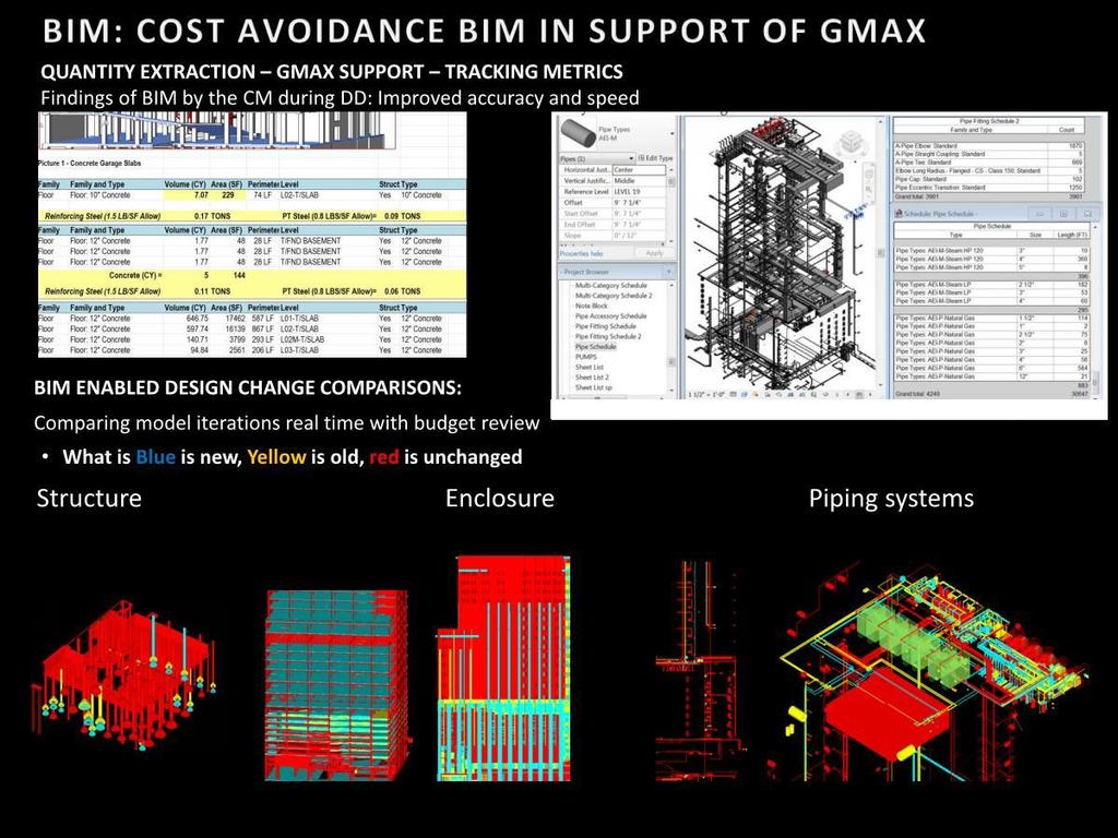
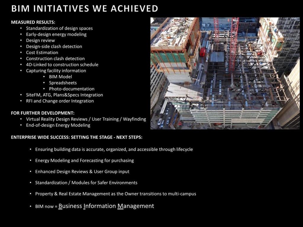
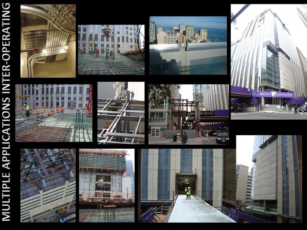
2 way. Multiple design options were undertaken early in the project in order to do quick take offs to determine which design option meets the required fenestration ratio for energy loss. This allows us to pick the most efficient design option and maintains that Revit schedule as a live working document in our project; we can always back check our findings in case there is a design change. We input the filtering once and that filter is maintained & live throughout the project s history. In our project we had about six different glazing types, with Revit we were able to color code, schedule and identify those glazing types quickly, which is essential in a one million square foot building. Project Scope: 990,000 SF Mixed use Medical office space, examination rooms and suites, 21 ambulatory surgery rooms and advanced Diagnostics and Treatment. With a 575 car parking garage that connected to the a neighboring parking garage on the South via pedestrian bridge with a second bridge and tunnel connecting to the existing Feinberg Hospital Facility. 25 story structure that was increased a floor to 26 stories to increase neighborhood parking, note this change was issued late in the construction document phase utilizing BIM $334 Million Construction Budget, 30 Month Schedule Registered for LEED certified (pending) BIM was used as a new method of designing and visualizing the work. Design problems such as the rearranging of mechanical components and structure, were changed early on with the team during review and this just wouldn t have been possible with conventional two dimensional AutoCAD. Solving issues between the design architect and the project architects were more easily achieved in reviewing them in BIM with no explanations needed; these issues are put into plan, section and elevation with 3 clicks of the mouse. This client has taken full advantage of the BIM process, embracing it and requiring the colocation of the design team and the construction team in a single office and customized a technology room on the eighth floor of a neighboring building overlooking the site. Building Users & Facility Managers, regularly reviewed the models in this virtual lab. Our client built a BIM room on their campus which overlooks the building site. Within this BIM room we have collaborated with doctors, nurses, facilities, consultants, architects, contractors and project managers; we communicate on 2 large smart boards viewing the Revit models and Navisworks. We have used the Revit model s medical equipment families that have embedded smart links to the internet showing the medical equipment images and specifications, which allows for quicker User sign off of specifications and locations. We used Revit and Navisworks to do fly throughs of clinic spaces; as a tool for nurses to determine their work flows in their new spaces. We utilized the smart boards in the clients Tech room to diagram multiple work flows and patient flows; these processes can become increasingly complicated as clinic spaces can have multiple functions including: X ray, blood draw, procedure, changing rooms, checkin/out, waiting/sub waiting and exam rooms. This process became crucial not only for design, but for the hospital Doctors to determine best practices. We didn t just make engineering and architecture more integrated; it actually improved the building s end users productivity through simulation of reallife work flows before it s even built. The Benefits achieved
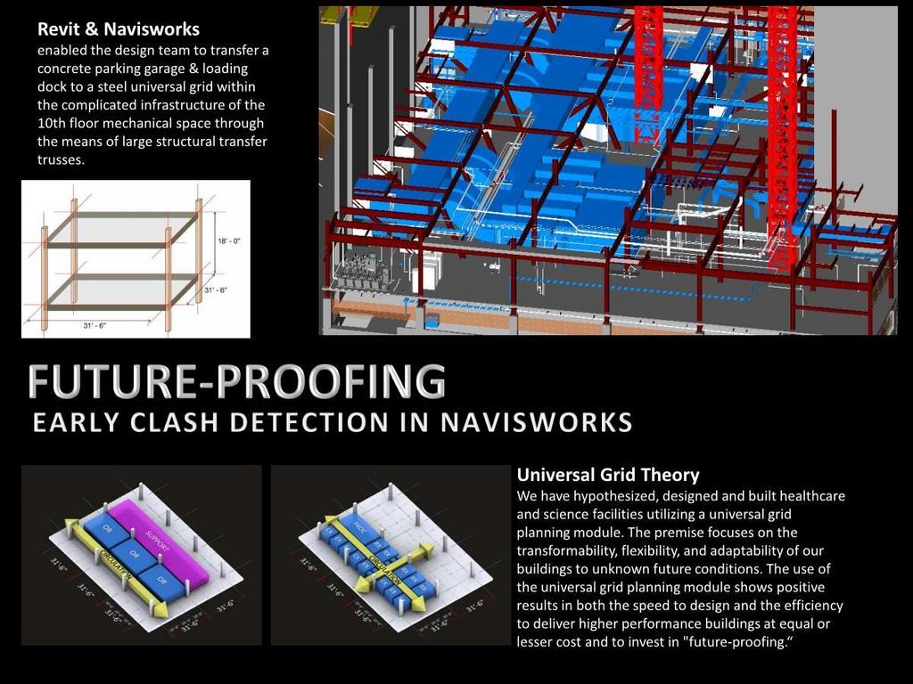
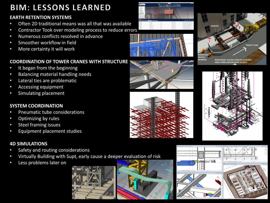
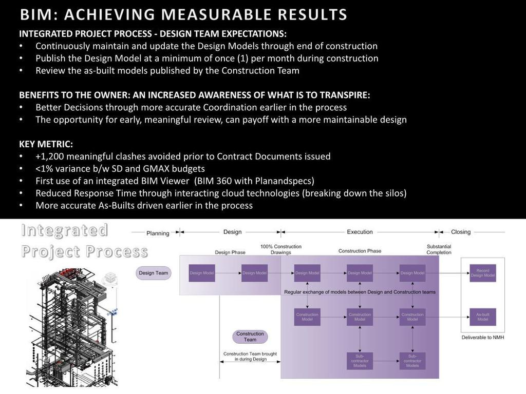
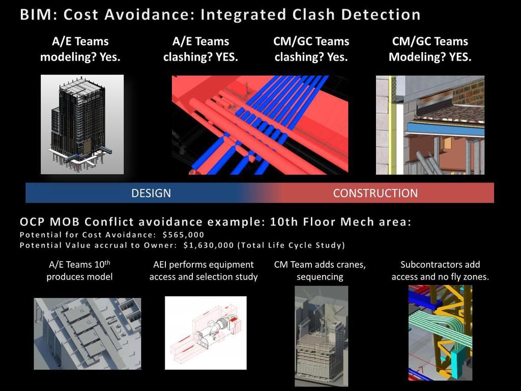
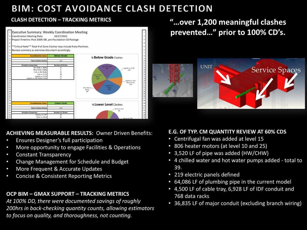
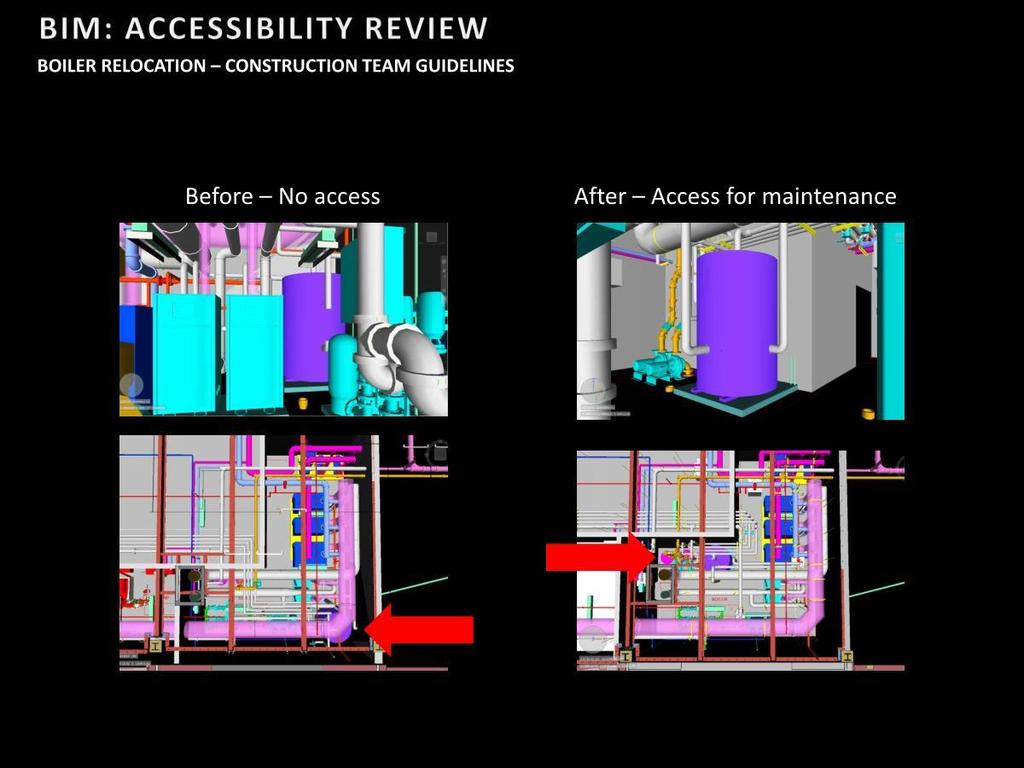
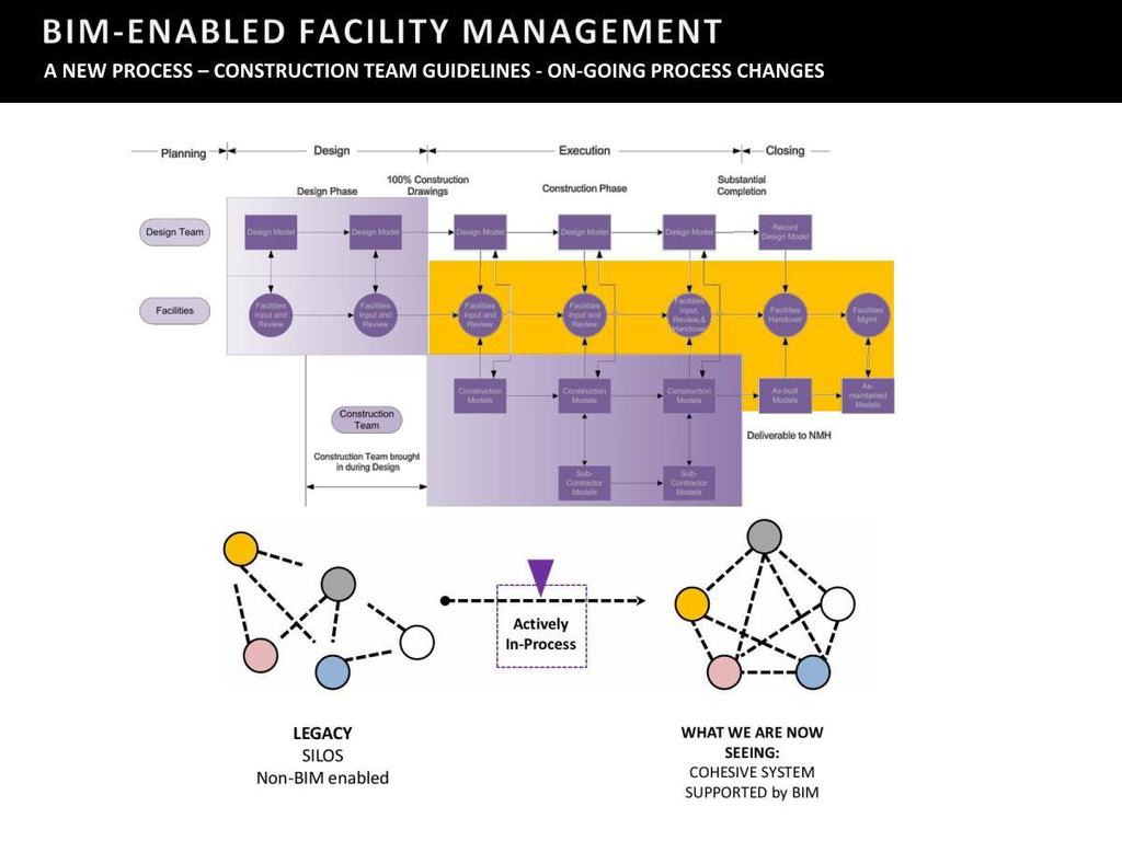
3 Developing Processes that re used the data with the following benefits: As built measurements pushed back into the model For caisson centers, Bracing locations, whalers, catch basin locations and column centerline verifications. This helped the detailing efforts with a more true indication of what was happening in the field. Owner Benefits Early review of design with the department heads and facilities and early tagging listing of all major serviceable equipment helped to lead the process of refining data. Life Cycle Improvement Constant studies were made during the equipment selection, for access for servicing, life cycle studies compared to service life costs, through interaction of the Mechanical engineers and the contractors making equipment purchases. Business Factors Although we do have stats, like the fact that 15,575 conflicts were resolved with the design even before the design models began the detailing process, through a cloud based portal solution i, the real story was catching things so early we didn t even bother to price then the original way. Like re orientating the steel trusses on the 10 th floor that transferred column loads, to make it easier to set and access the primary air handling systems. Stretching the building An entire floor was added the Construction Document model evolution, as an outcome of a neighborhood review meeting that sought more parking. Collaboration Requirement Tablet technology was deployed to verify and study installation sequencing. Senior Supt. Bill Boscelli saw this as a cultural change for our industry. After I took my first tablet in the field and could see what was happening before it happened, it really struck me how powerful all this (technology) really is. Bridge and Tunnel sequence installations After studying the assemblies, numerous changes were made to anticipate the emergency exiting needs of the neighboring buildings as well as proper fit up and erection of the structure and enclosure systems. Saving time and costs documented on average of 5% for each trade but more value was gained earlier with crane placement and Earth retention system site logistics. The non tech stuff This was a new way of working for many of the team members. It required an open way of thinking; A blurring of roles, being flexible toward change. It involved the field supervisors working directly with the design team to suggest and work out issues, utilizing visualizations to pre plan, but at the same time, owner representatives were challenged to verify if the program was correct. An example of this was the situation with the engine generators. When reviewing the design model, the owner expressed concerns with the location of the engine generator radiation exhaust the heat was a problem for the people working in this area. Technology & Innovation Implementations Scenario based Project Planning Automated Design through model generations Integrated, Consultant models copying elements Intelligent schedules and ID tagging Intelligent trenching of underground work (scans and hydro excavation as model underlays) Facility Mgmt., Coordination review Virtual OR mockup; review by users Technology room overlooked job i Original BETA test of Horizontal Glue before the Autodesk acquisition.
4
5
6
7
8
9
10
11
12
13
14
15
16
17
18
19
20
21
22
23
24
25

26
27
28
29
30
31
32
33

34
35
36
37
38
39
40
41
42
43
44