Public Water Supply District #2 of St. Charles County, Missouri
|
|
|
- Calvin Harper
- 5 years ago
- Views:
Transcription
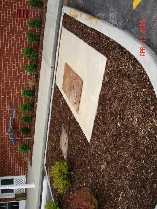
1 Public Water Supply District #2 of St. Charles County, Missouri POLICIES, PROCEDURES, AND REQUIREMENTS FOR CONNECTION AND INSPECTIONS OF: RESIDENTIAL WATER AND/OR SEWER SERVICE CONNECTIONS COMMERCIAL WATER AND/OR SEWER SERVICE CONNECTIONS FIRE PROTECTION LINES Revised June 2005
2 TABLE OF CONTENTS: Connection of Water Services and Sewer Inspection Information Page(s) PART I General Rules and Regulations 2-3 Sections A J Subsections D-1 through D-6 PART II Small Water Service Information, Specifications, and Requirements 3 6 Sections A D Subsections D-1 through D-26 PART III Small Water Meter Information, Specifications, 6-7 and Requirements Sections A G Subsections D-1 through D-4 PART IV Large Service and Meter Information, Specifications 7-10 and Requirements Sections A L Subsections J-1 through J- 16 PART V Fire Protection Line and Detector Check Information, 10 Specifications and Requirements Sections A B Subsections B-1 through B-10 PART VI Small Sewer Connection (Lateral) Inspection Information, Specifications, and Requirements Sections A - E Subsections C-1 through C-7, D-1 through D-11, E-1 through E-3 1
3 Connection of Water Services and Sewer Inspection Information PART I - General Rules and Regulations A) All water and/or sewer connection fees must be paid at least 48 hours prior to the scheduling of a typical residential water and/or sewer connection and/or inspections. A minimum of 24 hours in advance is required for the scheduling of water and/or sewer inspections and connections and will be scheduled on a first come, first serve basis and depending on personnel and/or material availability. B) All ¾ and 1 water service connections within the Public Water Supply District No. 2 (Water District) service area shall be performed by Water District personnel. Under no circumstances shall a builder, contractor, plumber, or owner make a ¾ or 1 connection to a Water District main. All 1-1/2 and larger water service connections shall be performed by the contractor, builder, plumber, or owner with the Water District s inspection and approval and must meet all applicable Water District rules, regulations, and specifications. C) All connections made to privately owned water mains or fire loops fed from the Water District s distribution system shall made by the builder, contractor, plumber, or owner and must be inspected and approved by the Water District. All materials used to make a service connection to a private line shall meet all applicable Water District rules, regulations, and specifications. No water service shall be connected nor the water meter installed until the private main or fire loop has been successfully pressure and bacteriologically tested in accordance with Water District requirements and procedures. D) The following are the responsibility of the contractor, builder, plumber, or owner who is requesting to establish water and/or sewer service within the Water District service area. The Water District reserves the right to refuse service if any of these do not meet its requirements. D-1) Proper sizing of the water and/or sewer service/lateral D-2) Proper excavation of water tap holes as shown in Tap Hole Dimensions Detail A D-3) Proper shoring or sloping of the banks of the tapping hole in accordance with all applicable OSHA and Water District safety rules and regulations D-4) Proper barricading of water tap and/or sewer inspection holes and trenches D-5) Proper installation of all components associated with the connection of new water and/or sewer customers to the Water District s distribution and/or collection systems D-6) Proper backfilling, compaction, grade, and landscape restoration of tap holes and/or service line trenches E) No connection shall be made nor will an inspection be approved, unless all materials are installed as required in the following rules, regulations and specifications. One return trip to an unsatisfactory installation and/or inspection will be allowed. For the second return trip and all trips thereafter; the contractor, builder, plumber, or owner shall be charged a minimum of a $25 (twenty five dollar) service charge, which shall be paid prior to the re-scheduling of an 2
4 installation and/or inspection. All penalties charged will be as allowed under the latest revision of the Water District s Rules and Regulations. F) The contractor, builder, plumber, and/or owner shall be responsible for all materials and maintenance issues associated with the water service connection dedicated to the Water District for a one year period, which shall begin from the date the water meter is installed and the initial water service is started by Water District personnel. The Water District shall assume responsibility for all ¾ through 2 service lines connected to Water District owned mains from the connection to the water main to the exit point of the service from the meter tile/pit one year after the meter installation and the start of water service. Water District responsibility for any maintenance issues associated with installation of dual meter settings shall begin one year after the second meter is set and the second water service is started. G) Under no circumstance shall a meter setting be by-passed by use of a meter idler, bypass valve, or any device which prevents the proper billing of water consumption by the Water District. Water and/or sewer service shall be disconnected and no future water and/or sewer service initiated before being deemed acceptable by the Water District. The Water District mandates that it is a crime to tamper with or operate any appurtenance of the Water District s water distribution system without the prior written approval of the Water District. Anyone found to have tampered with the public drinking water system or the public sewer system may also be prosecuted under federal, state and/or local laws. H) The Water District prohibits the installation of any domestic water meters and/or detector check valve meters within the interior of a building or structure. I) Any change to the grade or ground level that necessitates the raising or lowering of the meter tile/pit will require prior written Water District approval and will be made solely at the customer s and/or home owner s expense. J) The Water District reserves the right to update and/or revise the rules, regulations, and specifications contained within its policies that it deems in its best interest at any time. PART II - Small Water Service (3/4 through 2 ) Information, Specifications, and Requirements A) Supplier of materials and labor for water service line connections. A-1) The Water District shall be responsible for providing the saddle, the corporation stop, the meter, the meter gaskets, and the labor necessary to connect all ¾ and/or 1 services to Water District owned and/or maintained 2-12 PVC water mains. A-2) On 1-1/2 and 2 water service connections the Water District will supply only the water meter, the gaskets, and the bolts and nuts needed to complete the service installation. The builder, contractor, plumber, or owner shall provide all other materials including the tapping saddle as well as the labor and installation. A-3) On all ¾ through 2 connections on mains larger than 12 in diameter, the builder, contractor, plumber, or owner shall provide the labor and installation of the connection. The builder, contractor, plumber, or owner shall also provide all materials including the 3
5 tapping saddle for mains larger than 12 in diameter. Specifications and requirements for all such connections shall be at the discretion and determination of the Water District. A-4) All 1-1/2 and 2 service connections must be witnessed by the Water District with the coupon from the wet tap to be supplied to Water District personnel. B) All other materials for ¾ through 2 services including the copper service line, the water meter setter, the meter tile/pit, the frame and cover, and any blocking materials deemed necessary shall be supplied and installed by the builder, contractor, plumber, or owner. C) All 1-1/2 and larger water services designed to supply a commercial building or development shall submit two copies of a utility site plan for Water District review and approval no less than 8 weeks prior to scheduling of the water service connection and/or inspection. All other 1-1/2 and/or 2 water service connection requests shall be submitted for approval by the Water District no less than 48 hours prior to their installation by the builder, the contractor, the plumber, or the owner. D) All ¾ through 2 water services shall be installed in accordance with the following specifications and material requirements as shown in the Typical Service Details B, C, D, E, and F : D-1) ¾ and 1 water services must be Type K copper from the water main to 3 beyond the discharge (downstream) side of the meter setter. D-2) 1-1/2 and 2 water services must be Type K copper from the water main to 3 beyond the discharge side of the meter. On road crossings or services that exceed 20 in length between the water main and the meter tile/pit, 1-1/2 or 2 SDR 200 p.s.i. C.T.S. poly pipe ( poly ) may be substituted with the Water District s written approval. D-3) Poly service lines permitted to be installed between a Water District main and the meter tile/pit shall require 12 gauge, solid strand, and coated wire to be appropriately attached to the poly pipe with no less than 6 of wire stubbed up within the meter tile/pit. D-4) 1-1/2 and 2 services to be installed under pavement must be encased within a 4 conduit to extend no less than 2 from both edges of the street or roadway. Encasement of ¾ and 1 services may be required at the discretion of the Water District D-5) ¾ through 2 water services must be a continuous piece of pipe from the water main to the meter setter and contain no couplers, reducers, connections, bushings, or other coupling devices. D-6) ¾ and 1 service connections performed by the Water District must have Type K copper extended not less than 2 beyond the water main to facilitate the connection. D-7) ¾ and 1 services must be installed so that the service line can be connected to the corporation stop and service saddle at between the 10 o clock and 11 o clock position. D-8) 1-1/2 and 2 service saddles must be installed so that the corporation stop is in the 9 o clock position on the water main with the stem in the 12 o clock position. 4
6 D-9) 1-1/2 and 2 services must have approved masonry blocking between the bottom of the corporation stop and firm soil. Blocking of the corporation stops for ¾ and 1 services may be required at the discretion of the Water District. D-10) ¾ through 2 water services must be laid straight and perpendicular from the connection on the water main to the Type K copper exiting the meter tile/pit. D-11) Back-tap connections (connections to the side of the water main opposite the meter) are prohibited. D-12) Dual meter settings must be installed on the property line of the 2 residences or structures to be served. D-13) Meter tiles/pits must be located no less than 12 and no more than 15 from the edge of the street or roadway. D-14) Meter tiles/pits must not be installed under pavement of any kind including sidewalks, bike paths, driveways, parking lots, or behind fencing, under landscaping, in ditches, drainage areas, or in any setting that restricts the Water District from unobstructed access. D-15) Meter tiles/pits for ¾ through 2 water meters must be the prefabricated high density polyethylene (plastic) type. D-16) Meter tiles/pits must be of the smooth interior and exterior wall design. Ribbed or corrugated meter tiles/pits are prohibited. The interior must be white. D-17) Meter tiles/pits must not have risers and/or other means of raising or elevating the meter tile/pit to the finish grade or ground level. Meter tile/pit frames and covers must be the prefabricated cast iron type. D-18) Meter covers/lids must be the small nut locking type, must be drilled to accommodate either touch or radio read meters, and must be installed flush with the finish grade of the ground or yard. D-19) Meter tiles/pits, frames, and covers must be sized as follows: D-19-a) Single 5/8 x3/4 meter sets require a 18 x30 meter tile/pit with an 18 frame and a locking small nut cover with one 1-7/8 diameter hole in the cover. D-19-b) Dual or double 5/8 x3/4 meter sets require a 20 x30 meter tile/pit with a 20 frame and a locking small nut cover with two 1-7/8 diameter holes in the cover. D-19-c) Single 1 meter sets require a 20 x30 meter tile/pit with a 20 frame and a locking small nut cover with one 1-7/8 diameter hole in the cover. 5
7 D-19-d) Single 1-1/2 and 2 meter sets must be installed in a 36 x36 meter tile/pit with a 36 x 20 cast iron adapter ring, a 20 frame, and a locking small nut cover with one 1-7/8 diameter hole drilled through the cover/lid.. D-20) Single meter setters must be of the prefabricated copper setter type with compression fittings on both the inlet and outlet sides of the setter. D-21) Meter setters must be equipped with a ball angle valve and lock rings on the inlet side of the meter, and a single check valve on the discharge side of the meter. D-22) Dual 5/8 x3/4 meter settings must be installed using a 1 compression inlet by dual ¾ outlet U-branch brass fitting and 2 tip and nut setters to split the services. D-23) 1-1/2 and 2 meter setters must be equipped with a bypass line containing an angle ball valve with lock rings. D-24) Meter setters must be a minimum of 15 below the ground or finish grade level, but no more than 20 from the ground or finish grade level. D-25) Water services must have a minimum of 32 and a maximum of 42 of acceptable cover or backfill. D-26) ¾ through 2 meter setters must be centered within the meter tile/pit and the inlet and outlet piping must be fully exposed within the meter tile/pit. PART III - Small Water Meter (5/8 x3/4 through 2 ) Information, Specifications, and Requirements A) All 5/8 x ¾ through 2 water meters shall be installed by Water District personnel. The Water District shall install the type, brand, and size meter it deems in its best interest to properly bill the contactor, builder, plumber, or owner for water consumption. B) Water meters must be sized properly and shall coincide with the size of service line running from the water main to the meter setter. C) The Water District shall supply all washers, gaskets, bolts, and nuts to properly set all 5/8 x3/4 through 2 water meters. D) The Water District requires the following spacing between the flanges on all 5/8 x ¾ through 2 meter setters installed within the Water District: D-1) 5/8 x3/4 meters require a minimum of 7-1/4 and a maximum of 7-1/2 between the flanges. 5/8 x3/4 meters have a 7 lay length D-2) 1 meters require a minimum of 11 and a maximum of 11-1/4 between the flanges. 1 meters have a 10-3/4 lay length 6
8 D-3) 1-1/2 meters require a minimum of 13-1/4 and a maximum of 13-1/2 between the flanges. 1-1/2 meters have a 13 lay length D-4) 2 meters require a minimum of 17-1/4 and a maximum of 17-1/2 between the flanges. 2 meters have a 17 lay length E) Interior plumbing must be completed or an appropriate shut off valve installed on the customer maintained service line before the water meter is installed and water service is initiated. F) Meter pits must be easily accessible, free of debris, and the meter pit cover exposed at finish grade level for the water meter setting to be facilitated. G) Failure to meet Water District specifications, rules, and regulations concerning the proper installation of water meters by the builder, contractor, plumber, or owner will require one return trip by Water District personnel to facilitate a meter setting. A second return trip and all trips thereafter will result in a $25.00 trip charge being assessed, which shall be paid by the builder, contractor, plumber, or owner prior to the re-scheduling of a meter installation. PART IV - Large Meter and Service Line (3 and larger) Information, Specifications, and Requirements A) The Water District requires that a detailed utility site plan be submitted and approved in writing for all buildings and/or developments that will be served through a 3 or larger water service before any connection can be made to either a Water District owned main or private main/system supplied water by the Water District. Plans should be submitted at least 8 weeks in advance. This time period allows the Water District to perform the utility site plan review necessary for the project to proceed. Depending on the size and type of the meter and/or strainer required for a project, at least 8 weeks may be needed for the ordering and shipment of the necessary water meter and/or strainer. B) Connection fees, meter costs, strainer costs, and any additional charges attributed to a project or development, must be paid prior to any connection and/or meter setting. C) Commercial developments, buildings, or projects constructed in various stages or phases which are to have their water consumption measured by one domestic water meter must pay all connection fees associated with the entire project in advance of any connection being made to the Water District s distribution system. D) Large service connections must not be larger than the Water District main to which it is attached. The size of the service connection and meter shall be subject to the limitations set by the Water District and shall be based on the ability of the water distribution system to handle the expected demand. The Water District may require the owner or developer to pay the full cost of increasing the size of water mains in the area of the property in order to meet the demands of the property being served by the proposed service connection. E) Start-up of large service connections and privately owned systems require successful pressure testing and bacteriological testing meeting the requirements set forth in the Water District s 7
9 Water Distribution System Specifications. Results of these tests must be submitted and approved by the Water District. F) All large live taps (wet taps) must be witnessed by Water District personnel with the coupon provided upon the completion of the tapping process. G) Water service connections 3 and larger shall be considered private from the discharge side of connection valve (or tapping valve in the case of a wet tap). The Water District will own only the connection, the valve and valve box adjacent to the connection and the meter(s). Therefore, all maintenance of privately owned lines/systems shall be the responsibility of the property owners. H) Tapping sleeves, valves, and valve boxes used to connect large privately owned mains or systems to the Water District must meet the rules and regulations noted in the Water District s Water Distribution System Specifications. I) Large water meters serving, or being served from, privately owned mains or systems must meet all applicable specifications, rules and regulations of the Water District. J) Large water meters and services within the Water District must be installed as detailed in the Typical Large Service Detail G and/or as described below: J-1) Water meters must be installed in prefabricated concrete meter vaults and at the location pre-approved by the Water District. The use of pyramid boxes for domestic meter installations is prohibited. J-2) Water meter vaults must be constructed by Champion Precast Inc., or an approved equal. J-3) Water meter vaults must be installed in green-space and made easily accessible by the Water District at any time (24 hours a day and 365 days a year without exception). Only Water District personnel shall determine if the physical conditions at a specific location are considered accessible. J-4) Water meter vaults must be installed in a manner so that all vault lids will be at finish grade or ground level. They must not be raised to grade by use of meter box chimneys or any other method. J-5) Water meter vault lids must have an access manhole and/or frame and cover located directly above the meter to provide ample space for servicing or removing the meter. J-6) Water meter vaults must be installed to have a maximum interior depth of no more than 6 6 and to have minimum interior depth of no less than 4 6. J-7) Water meter strainers must be supplied by the Water District and installed immediately upstream from the meter. 8
10 J-8) Water meters must be supplied by the Water District. The Water District will supply the meter and strainer type, brand, and size it deems in its best interest. J-9) Water meters must be installed with properly sized bypass piping and gate valves to be located within the meter vault, when required. J-10) Resilient seated gate valves must be installed on all piping within the water metering vault. J-11) Piping within the metering vault is required to have a mechanical joint sleeve or approved flanged coupling adapter installed on the exit side of the meter and strainer and between the 2 meter isolating valves. J-12) Ductile iron pipe installation is required within the metering vault and extending for no less than 6 on both the inlet and outlet piping. J-13) Inlet and outlet ductile iron meter vault piping is required to be properly restrained at the connections outside the meter vault. J-14) Inlet and outlet piping must be sealed with water tight non shrinking type mastic or grout where the piping enters and exits the meter vault walls J-15) The gaskets, bolts, and nuts needed to install large water meters and/or strainers shall be supplied by the Water District. J-16) Proper spacing is required for the installation of the water meter, the strainer, the gaskets, and the bolts and nuts. K) Large domestic water meters are typically supplied in following sizes and type. Also included is the meter (M.L.L.) and strainer lay lengths (S.L.L.). SIZE TYPE M.L.L. S.L.L. 3 (three inch) Compound 17 (seventeen inches) 6 (six inches) 4 (four inch) Compound 20 (twenty inches) 7-1/2 (seven and one half inches) 6 (six inch) Compound 24 (twenty four inches) 9 (nine inches) 8 (eight inch) Compound 55 (fifty five inches) 10 (ten inches) 4 (four inch) Fire Service 33 (thirty three inches) N/A 6 (six inch) Fire Service 45 (forty five inches) N/A 8 (eight inch) Fire Service 53 (fifty three inches) N/A 10 (ten inch) Fire service 68 (sixty eight inches) N/A L) Additional water meter and strainer information or specifications will be provided upon request and at the discretion of the Water District. 9
11 PART V - Fire Protection Line and/or Detector Check Valve Information, Specifications, and Requirements A) Fire protection lines and systems must meet the guidelines described in the Water District Rules and Regulations. B) Additional information, requirements, and specifications concerning fire protection lines are as follows: B-1) Detector check vaults and/or pyramid boxes must be located in green-space and made easily accessible by Water District personnel. Only the Water District will determine if the physical conditions at a specific location are considered accessible. B-2) Detector check vaults and/or pyramid boxes must be constructed by Champion Precast Inc. or a Water District approved equal. B-3) Detector check vaults and/or boxes must use an approved light square frame and circular cover with 1-7/8 diameter hole to accommodate a touch or radio read meter. B-4) Detector check valve vault and/or box lids must be installed flush with the ground level and the frame and cover is prohibited from being raised to grade by use of bricks, concrete blocks or any other method not deemed acceptable by the Water District B-5) Detector check valve installations must include all piping that will facilitate the installation of a Water District meter. The Water District will supply only the meter and the gaskets and/or washers needed to set the meter. B-6) Detector check valve assemblies must be installed using Water District owned meters which have lay lengths as described in this document. B-7) Detector check valve piping that connects the Water District owned meter to the valve assembly is required to be no more than 42 below the frame and cover and/or the finish grade level. B-8) Detector check valve piping that connects the Water District owned meter to the valve assembly is required to have ball valve on the inlet side of the meter and a single check valve and a ball valve on the discharge side of the meter. B-9) Private fire protection mains and fire hydrants not required to be piped through a detector check valve assembly shall be allowed only at the Water District s discretion. B-10) Private fire protection mains and hydrants must be piped and located on the exterior of all buildings and/or structures. 10
12 PART VI - Sanitary Sewer Lateral Connection and Inspection Information, Specifications, and Requirements A) All sanitary sewer laterals connected to the Water District s collection system must be inspected by the Water District and shall be fully exposed from the footing of the building to the sewer main or the previously installed and approved stub out. B) All sanitary sewer connection fees must be paid no less than 48 hours prior to the scheduled inspection. All sewer inspections must be scheduled no less than 24 hours prior to the requested inspection and will be based on a first come first serve basis and depending on Water District personnel availability. C) All sanitary sewer service connections (taps) and materials used to connect to a Water District pressurized (force) main shall be installed by the builder, contractor, plumber, or owner and meet with Water District approval. The following are requirements and specifications for the proper installation of connections to a Water District pressurized (force) main. Any deviation to the following shall be at the Water District s discretion and made on a case by case basis. C-1) A 12-gauge, single strand, and coated tracer wire is required to be installed with the customer s pressurized service line from the grinder pump to the corporation stop box where it shall be stubbed up on the exterior of the corporation stop box and made easily accessible. C-2) Tapping saddles and corporation stops must be of brass construction. C-3) Tapping saddles must be installed so that the corporation stop is in the 9 o clock position on the force main. C-4) Corporation stops must be installed with the stem in the 12 o clock position. C-5) A single check valve is required to be installed within 1 of the corporation stop on the customer s pressurized service line to prevent sewage from flowing back towards the customer s grinder pump, residence, or building. C-6) Corporation stop boxes must be installed allowing for easy access at all times. C-7) The stop lid or cover is required to be installed flush with the finish grade or ground level and should clearly be marked or identified as sanitary sewer. D) All gravity sanitary sewer laterals connected to Water District s collection system and installed by the builder, contractor, plumber, or owner, must meet the following rules, regulations, and specifications. Any deviation to the following will be at the discretion of the Water District and addressed on a case by case basis. D-1) Laterals must be connected using preexisting sewer stub outs, service wyes, or service tees where available. 11
13 D-2) Laterals must be installed with a minimum 2% fall (slope) from the building to the stub out or the connection at the sewer main. D-3) 3 of schedule 40 grade PVC piping is required from the interior and exterior walls of the footing and/or foundation. D-4) All remaining piping from the connection at the sewer main or pre-installed stub out to the buildings footing and/or foundation is required to be no less than schedule 35 PVC pipe. D-5) Laterals that are installed with greater than 15 of backfill or cover must use schedule 40 grade PVC piping. Heavier grade piping must be used if recommended by the pipe manufacturer or required by the Water District. D-6) Laterals in excess off 100 in length must have a clean out located every 100 of piping. D-7) Laterals must have a clean out within 10 of the footing or foundation. D-8) Laterals are prohibited from containing bends greater than a 45 degree angle. D-9) Lateral piping and fittings must be installed and connected by use of purple primer and glue and/or bell and spigot type piping. D-10) Laterals must be installed on firm soil or appropriate granular bedding as recommended by the pipe manufacturer to prevent the movement or settling of the piping. D-11) Laterals installed beneath driveways, sidewalks, streets, or any other paved encumbrance must be backfilled the entire depth of the trench or excavation with 1 granular rock to 90% Standard Proctor or Water District approved equal. E) When stub outs are not provided or clay tile piping is present, laterals must be connected to the Water District s collection system by using the following methods and materials. Any deviation to the following shall be at the Water District s discretion on a case by case basis. E-1) Laterals to be connected to a clay tile sewer main shall be connected as follows. E-1-a) A full section of the clay tile pipe and the bell end must be removed and replaced with P.V.C. piping of the same diameter containing either a tee or wye branch fitting to facilitate the lateral connection to the main. E-1-b) A Fernco brand repair coupler or approved equal shall be used to connect the PVC fitting and pipe to the clay tile piping. E-1-c) The exposed clay tile main and new service connection shall be bedded on 1 granular rock and then completely encased in concrete from 1 beyond each 12
14 Fernco coupler (or approved equal) on the upstream and downstream connections to the top of the piping. E-2) Laterals permitted to be connected to the sewer system at a manhole shall be installed by means of an outside drop. The outside drop lateral is required to be installed as follows. E-2-a) All outside drop piping must be at least schedule 40 grade piping, which shall extend no less than 4 beyond the excavations over dig at the manhole. E-2-b) The outside drop is required to discharge in the direction of the downstream flow and may, at the Water District s discretion, require grouting of the manhole bench to direct the flow. E-2-c) The outside drop is required to be banded by use of stainless steel strapping material to the manhole every 2. E-2-d) The outside drop is permitted to extend within the manhole at both customers lateral elevations and at the point where it shall discharge into the Water District s collection system. E-2-e) The drop lateral entry points into the manhole must be sealed by means of a non-shrink type grouting which shall meet with Water District approval. E-2-f) Grouting used for outside drop laterals is required to be left exposed for a minimum of 5 hours to allow for the grouting material to properly cure E-2-g) The exterior of the manhole cone is required to be tarred and resealed before backfilling of the outside drop lateral. E-2-h) Backfilling of the outside drop lateral must occur the same day the piping is installed and the grouting and resealing of the manhole is performed. E-3) Laterals to be connected to a PVC sewer main where a preexisting tee or wye on the main is unavailable must be connected as follows. E-3-a) A PVC sewer tapping saddle is required to be both glued and banded to the sewer main. E-3-b) The saddle is required to be installed above the flow line of the sewer main at approximately a 45 degree angle. E-3-c) The customer s PVC lateral is required to be connected to the service saddle by use of purple primer and glue or by using bell and spigot piping and fittings. E-3-d) The coupon removed during the sewer tap must be provided to the Water District. 13
15
16
17
18
19
20
21
22
23
24
25

26