COVER FEATURE. Micropile. Design Minimizes. California Edison Project
|
|
|
- Augustine Jones
- 5 years ago
- Views:
Transcription
1

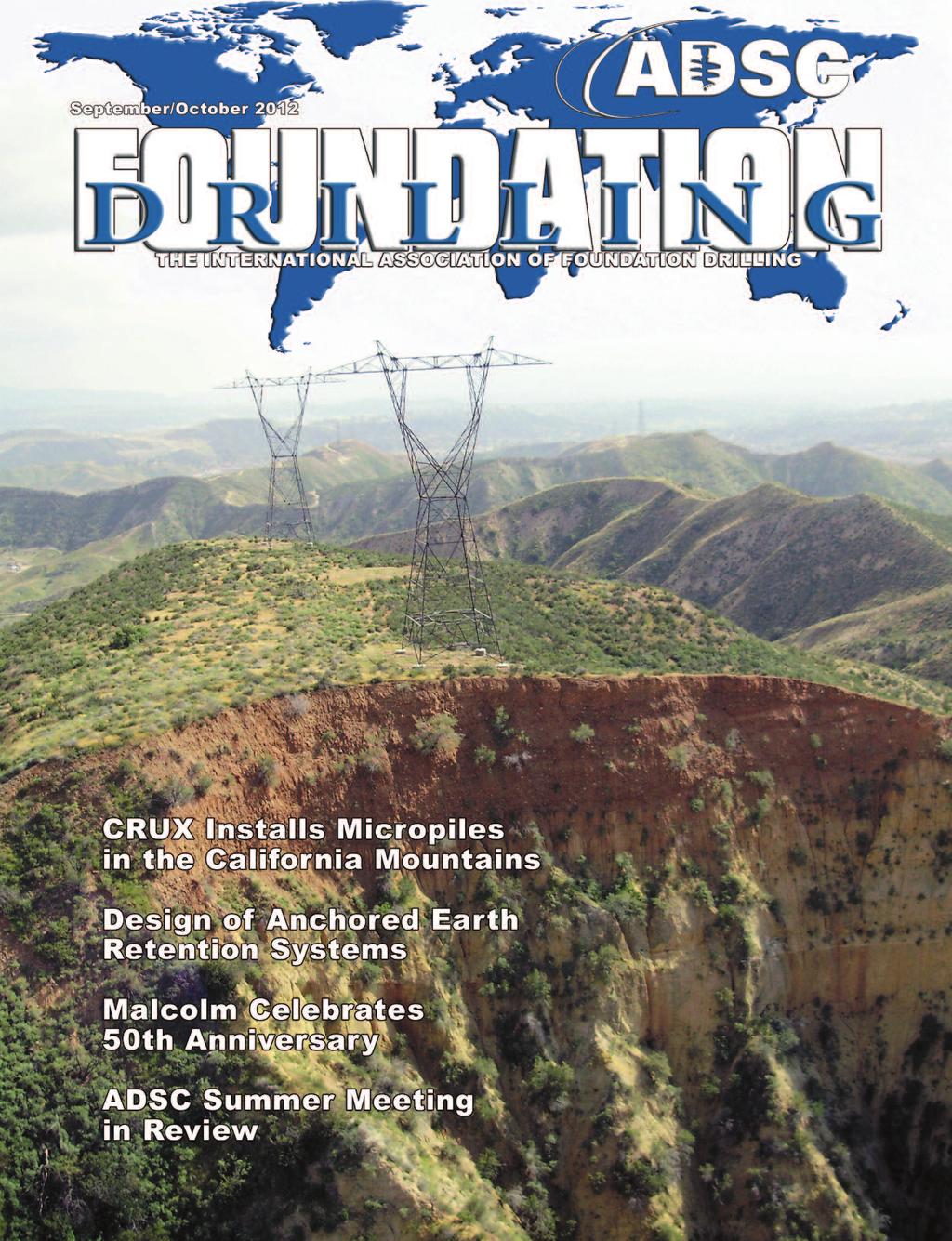
2 COVER FEATURE Micropile Foundation Design Minimizes Environmental Impact for Southern California Edison Project by Chih-Hung Chen, P.E., Burns & McDonnell, and Nick Salisbury, Crux Subsurface, Inc. Micropiles are one of the deep foundation systems that fall under the ADSC Technical product umbrella. The following article which describes the use of micropiles as a deep foundation solution in a very remote enviroment comes to Foundation Drilling magazine from ADSC Contractor Member, Crux Subsurface, Inc., Spokane, Washington.(Editor) For construction within the Angeles National Forest, the U.S. Forest Service requires minimal disturbance of the land. An unconventional design and construction solution helped Southern California Edison (SCE) gain approval from the U.S. Forest Service. Background According to a report published by Southern California Edison, entitled The Future of Transmission, California has a strong appetite for electricity. And its residents increasingly favor a supply produced through renewable resources such as wind. (SCE) is one of the utilities that leads the pack toward meeting state mandates for renewable sources of power, having put The environmental measures required to permit and begin construction on the line may be a harbinger of things the electrical transmission industry must be prepared to manage as upgrades to the grid are made across the country in the coming decades. contracts in place for more than 20 percent of delivered power to come from renewable sources. A big part of SCE s effort is the Tehachapi Renewable Transmission Project (TRTP), which will Completed transmission power lines in Angeles National Forest. deliver renewable energy to customers in southern California. The Tehachapi Wind Resource Area is in Kern County, north of Los Angeles. The route from the wind farm area to the electrical grid traverses a range of land uses from urban residential to rural farmland. The terrain varies from flat, high desert to rugged mountains. Much of the construction for the TRTP takes place in remote, inaccessible locations. Critical segments cross the Angeles National Forest. To construct a 500-kV transmission line in California and across land managed by the U.S. Forest Service, SCE and its owner s agent, Burns & McDonnell, faced a level of scrutiny not experienced when most existing lines were constructed twenty or more years ago. The environmental measures required to permit and begin construction on the line may be a harbinger of things the electrical transmission industry must be prepared to manage as upgrades to the grid are made across the country in the coming decades. Not only in this instance but in general, transmission line projects are facing higher levels of scrutiny than ever before, and the Tehachapi Renewable Transmission Project in Kern County north of Los Angeles is no exception. The new 500-kV line crosses the Angeles National Forest, where the U.S. Forest Ser - vice has strict requirements. For example, for construction projects within the Angeles National Forest, the Forest Service requires minimal disturbance of the land. The Southern California Edison Report states when working in the Angeles National (Continued on page 17) Page 16 FOUNDATION DRILLING November/December 2012


3 Forest, nothing goes in or out on the ground. This includes equipment, supplies, crew, inspectors, and portable toilets. As a response an unconventional design and construction solution helped SCE gain approval from the U.S. Forest Service. In the initial design phase drilled shaft foundations were considered to be the most appropriate foundation system for this project. However, due to certain environmental restrictions and Micropile foundations, a high-capacity version of foundation solutions sometimes known as pin piles or mini piles because of their small diameter, provided cost and schedule advantages over other designs due to restrictions imposed by working within the forest. the very remote construction site, in this instance, it was necessary to consider other viable drilled foundation options. Helicopter-supported micropile foundations were selected as the optimal alternative. This article will discuss the foundation design selection process, as well as technical challenges encountered during implementation. Micropile foundations, a high-capacity version of foundation solutions sometimes known as pin piles or mini piles because of their small diameter, provided cost and schedule advantages over other designs due to restrictions imposed by working within the forest. Design Selection...Finished product. Micropiles being installed. The initial design for the TRTP included a drilled shaft foundation solution, which would have required constructing miles of access roads for drilling and construction equipment. Within the forest, access roads were not approved. In this case it was determined that due to the remoteness of the location drilled shafts were not a viable option, and that micropiles would provide an acceptable alternative. Other alternatives, including prestressed or post-tensioned rock anchors and micropile foundations, were considered. Rock anchor foundations, which use anchors to resist uplift and utilize bearing between concrete cap and rock to resist foundation rotation, compression, and shear loads, were deemed impractical because of the highly variable near-surface rock and soil conditions. Micropile foundations were proposed by the general contractor, PAR Electrical Contractors, as the foundation alternative. Foundations were designed by Crux Subsurface and its subconsultant and reviewed and approved by Burns & McDonnell and SCE. The foundation system was constructed by Crux and PAR. Micropiles typically range from 4 to 12 inches in diameter. They combine the uplift resistance of a rock anchor foundation with the compression and lateral bending resistance of a drilled shaft foundation. To install these small but high-capacity deep foundation members, Crux developed lightweight, componentized drill rigs that can be transported by helicopter and assembled at each site. Beyond environmental advantages realized by the elimination of road building, the lightweight materials and construction equipment create benefits including a significant reduction in spoils, elimination of fluids, reduced emissions compared to conventional equipment, and a smaller foundation footprint. These combine for (Continued on page 19) FOUNDATION DRILLING November/December 2012 Page 17


4 an overall reduced impact on the environment, which contributed to the approval of the Forest Service. On the TRTP, micropile diameters range from 5.5 inches to inches at depths between 25 and 51 feet. Groups of 3 to 12 micropiles per tower leg were constructed, depending on the tower type and soil condition. A geotechnical report for the project served as a basis for identifying soil type and condition. The The Federal Highway Administration s Micropile Design and Construction Guidelines Implementation Manual, which was developed with the assistance of members of the ADSC s Micropile Committee Federal Highway Administration s Micropile Design and Construction Guidelines Implementation Manual, which was developed with the assistance of members of the ADSC s Micropile Committee, and the Post Tensioning Institute s Recommendations for Prestressed Rock and Soil Anchors were used for initial assumptions of soil strength. Several sacrificial preproduction micropiles were tested to evaluate the ultimate grout-to-ground bond stress before construction began. A licensed geologist characterized the soil onsite for each tower footing during construction. The micropile design was considered to be advantageous because it could be adapted to accommodate individual site conditions by varying the pile length and/or adding additional piles to address anomalies that were not identified in the more general geotechnical investigation. The 224 micropile foundations Micropiles being installed in a batter. (four per tower) installed were grouped into three tower families. The number of piles and length of each upper cased section and lower bond section were installed to meet a minimum criteria for a variety of soil and rock conditions. After micropile installation, proof load tests were conducted at each tower site to confirm that piles met factored design loads. Technical Challenges The remoteness of the Angeles National Forest presented challenges. Micropile foundations utilize the complex interaction of numerous components including rock or soil, steel micropile reinforcement and casing, cast-in-place concrete and steel lattice stub angles. Comprehensive design of the entire foundation system is essential to ensure long-term tower performance. Micropiles are slender, flexible members. SCE required that the foundations meet stringent deflection criteria and have built-in safety factors to minimize stress buildup in the stub angle transferred up the tower leg and adjacent bracing member. Compliance with the desired deflection criteria was achieved by the arrangement of the piles within the group. (Continued on page 20) FOUNDATION DRILLING November/December 2012 Page 19


5 The ultimate finished foundation. batching, enhanced the need for project planning and execution. In the end, helicopter-supported micropile installations provided foundations that could meet strict design criteria, minimize ground disturbance and environmental impact, and provide scalability to adapt to varying ground conditions without downtime for further design or agency review. Project Team Getting equipment to the sites required the use of helicopters. In the end, helicopter-supported micropile installations provided foundations that could meet strict design criteria, minimize ground disturbance and environmental impact, and provide scalability to adapt to varying ground conditions without downtime for further design or agency review. Environmental factors such as wind, fog, and dry, hot weather that increased fire risk all had impacts on this helicopter supported project. Scheduling of critical items such as placement of concrete and micropile grout, each within a specified time of Project Owner: Contractor: Subcontractors: Consultants: Agencies: Southern California Edison PAR Electrical Contractors Crux Subsurface, Inc. Summit Helicopters Swanson Group Helicopters Mountain Air Helicopters Burns & McDonnell DCI Engineers Terracon Arroyo Engineering Consultants, Inc. U.S. National Forest Service California Public Utilities Commission Page 20 FOUNDATION DRILLING November/December 2012