Residential Energy Code Combustion Air and Make-Up Air
|
|
|
- Dulcie Jordan
- 5 years ago
- Views:
Transcription
1 Residential Energy Code Combustion Air and Make-Up Air Presenters Don Sivigny & Scott Nelson CCLD /DOLI
2 History of the Energy Code
3 History First Energy Code Became effective on January 30, 1976
4 History First Energy Code Became effective on January 30, 1976 Model Energy Code Phase
5 History First Energy Code Became effective on January 30, 1976 Model Energy Code Phase Chapter 7670 June 16, 1994
6 History First Energy Code Became effective on January 30, 1976 Model Energy Code Phase Chapter 7670 June 16, 1994 Chapter 7672 April 15, 2000
7 History First Energy Code Became effective on January 30, 1976 Model Energy Code Phase Chapter 7670 June 16, 1994 Chapter 7672 April 15, 2000 Mn. Rule 1322 June
8 Minnesota s Residential Energy Code What s Changing
9 Minnesota Rules Chapter 1322 The New Residential Energy Code, Incorporates Provisions for Radon Control however we are not discussing them today
10 N Scope This chapter regulates the energy efficiency for the design and construction of buildings regulated by the International Residential Code (IRC) as adopted and amended by the State of Minnesota.

11 Single Family Dwellings
12 Two Family Dwellings

13 Townhouses Inset townhouses picture here
14 N Scope This chapter shall also be used to meet the energy efficiency for the design and construction of new multi-family residential buildings regulated by the International Building Code (IBC) as adopted and amended by the State of Minnesota, that:
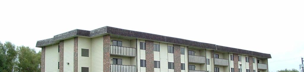
15 Scope (1) are not more than three stories in height;


16 These would be under the Residential Energy Code
17 This Building would be built to the Commercial Energy Code
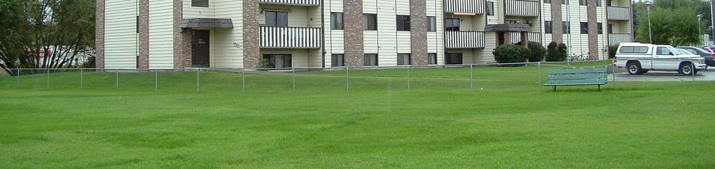
18 Scope (1) are not more than three stories in height; (2) contain no conditioned common space that is shared between dwellings;
19 This Building would Meet the Scoping Provisions
20 This Building would not Meet the Scoping Provisions Conditioned common space 4 5 6
21 Scope (1) are not more than three stories in height; (2) contain no conditioned common space that is shared between dwellings; (3) each dwelling unit contains a separate means of egress.

22
23 Scope The intent of these criteria is to provide a means for furnishing


24 Scope The intent of these criteria is to provide a means for furnishing 1. quality indoor air
25 Scope The intent of these criteria is to provide a means for furnishing 1. quality indoor air 2. assuring building durability
26 What is meant by durable buildings?
27 What is meant by durable buildings? Insurance company point of view
28 What is meant by durable buildings? Insurance company point of view Mortgage company point of view
29 What is meant by durable buildings? Insurance company point of view Mortgage company point of view Contractor point of view
30 What is meant by durable buildings? Insurance company point of view Mortgage company point of view Contractor point of view Code/Building Inspector point of view
31 What is meant by durable buildings? Insurance company point of view Mortgage company point of view Contractor point of view Code/Building Inspector point of view Owner/occupant point of view
32 What is meant by durable buildings? Insurance company point of view Mortgage company point of view Contractor point of view Code/Building Inspector point of view Owner/occupant point of view Other points of view
33 Why and where do the codes Energy code address durability?
34 Why and where do the codes address durability Energy code Required by the legislature to address it.
35 Why and where do the codes address durability Energy code Required by the legislature to address it. Should it be only a BTU code?
36 Vapor Retarders/Wall Durability
37 Vapor Retarders/Wall Durability Durability and moisture control are directly related
38 Vapor Retarders/Wall Durability Durability and moisture control are directly related Controlling moisture means controlling wetting and drying
39 Vapor Retarders/Wall Durability Durability and moisture control are directly related Controlling moisture means controlling wetting and drying Wetting is primarily controlled by air barriers, flashing and drainage plane improvements
40 Vapor Retarders/Wall Durability Durability and moisture control are directly related Controlling moisture means controlling wetting and drying Wetting is primarily controlled by air barriers, flashing and drainage plane improvements Drying is primarily controlled by air barriers and vapor retarders
41 Vapor Retarders/Wall Durability Durability and moisture control are directly related Controlling moisture means controlling wetting and drying Wetting is primarily controlled by air barriers, flashing and drainage plane improvements Drying is primarily controlled by air barriers and vapor retarders This is true on both the cold and warm sides of the wall
42 Why and where do the codes address durability What about the building codes
43 Why and where do the codes address durability What about the building codes Flashings
44 Why and where do the codes address durability What about the building codes Flashings Weather resistive barriers
45 Why and where do the codes address durability What about the building codes Flashings Weather resistive barriers Drainage (above and below grade)
46 Why and where do the codes address durability What about the building codes Flashings Weather rssistive barriers Drainage (above and below grade) Ventilation
47 Why and where do the codes address durability What about the building codes Flashings Weather resistive barriers Drainage Ventilation Others?
48 Water/Moisture/Bulk/Diffusion
49 Water/Moisture/Bulk/Diffusion When the rate of wetting exceeds the rate of drying accumulation occurs
50 Water/Moisture/Bulk/Diffusion When the rate of wetting exceeds the rate of drying accumulation occurs The drying potential of an assembly decreases with the thickness of the insulation and increases with the rate of air flow
51 Water/Moisture/Bulk/Diffusion When the rate of wetting exceeds the rate of drying accumulation occurs The drying potential of an assembly decreases with the thickness of the insulation and increases with the rate of air flow Energy conservation increases the thickness of the insulation and decreases the air flow
52 Water/Moisture/Bulk/Diffusion When the rate of wetting exceeds the rate of drying accumulation occurs The drying potential of an assembly decreases with the thickness of the insulation and increases with the rate of air flow Energy conservation increases the thickness of the insulation and decreases the air flow Energy conservation has a potential to increase moisture wall problems
53 Moisture Balances Occurring In the Exterior Wall Interior Exterior Interior Drying Exterior drying A typical house can have 10,000 pounds of studs and sheathing 10% moisture is 1,000 pounds or 125 gallons of water capacity
54 Building s Today are too close to the Edge of the Cliff 1950 drying 2005 wetting Point at which Water Accumulation Allows mold growth or rotting to occur National Experts have stated that moldy buildings today likely make up 5-10% of all housing. Before 1990 the failure rate was less than 0.1%
55 Moisture Balance in Walls Future Wetting Accum Drying
56 Scope The intent of these criteria is to provide a means for furnishing 1. quality indoor air 2. assuring building durability 3. permitting energy efficient operation
57 Scope Exceptions: There are several exceptions to the scoping provisions of this document and have been placed there by the committee to clarify its intent for construction and enforcement.

58 Portions of the building envelope that do not enclose conditioned space, including garages. Scope

59 Insulation R-values, air barrier and vapor retarder requirements are not required for existing foundations, crawl space walls, and basements in existing dwellings or existing dwelling units whose alterations or repair require a permit, if the original dwelling s permit was issued prior to the effective date of this chapter. Scope

60 Additions to existing dwellings or dwelling units may be made without making the entire dwelling or dwelling unit comply, provided that the addition complies with all the requirements of this chapter. Scope

61 Alterations and repairs to existing dwellings or dwelling units may be made without making the entire dwelling or dwelling unit comply. Scope

62 Scope Buildings that have been specifically designated as historically significant by the state or local governing body or, listed or, determined to be eligible for listing in the National Register of Historical Places.

63 Scope If a building houses more than one occupancy, each portion of the building must conform to the requirements for the occupancy housed in that portion. Insert picture of this type of building

64 This chapter does not cover buildings, structures, or portions of such buildings whose peak design energy rate usage is less than 3.4 Btu per hour per square foot or 1.0 Watt per square foot of floor area for all purposes. Scope
65 Compliance Climate Zones Climate zones from Table N or Figure shall be used in determining the applicable requirements from this chapter. Please note: These are different than what is in the national document. We are adopting the state map for frost and snow load but it is not consistent with the wind load chart that the structural committee adopted.
66 Climate Zones Northern Zone Southern Zone


67 Identification/Insulation Mark Materials, systems and equipment shall be identified in a manner that will allow a determination of compliance with the applicable provisions of this chapter.


68 Plans and specifications shall show in sufficient detail, pertinent data and features, of the building, the equipment, and the systems as herein governed, including, but not limited to: Plans & Specs


69 Building Thermal Insulation. All thermal insulation must conform to Minnesota Rules Chapter 7640, Minnesota Thermal Insulation Standards adopted by the Department of Commerce. For Foam Insulation we need to know and use the aged R-value
70 Building Thermal Insulation. Insulation shall be manufactured for its intended use, and installed according to the manufacturer's specifications. Insulation materials used on the exterior for the purpose of insulating foundation walls shall be a water resistant material and shall comply with ASTM C578, C612 or other approved standards.
71 Attic thickness markers. The thickness of blown or sprayed roof and/or ceiling insulation shall be written in inches on markers that are installed at least one for every 100 ft 2 (9.3 m 2 ) throughout the attic space. The markers shall be affixed to the trusses or joists and marked with the minimum initial installed thickness, with numbers a minimum of 1 inch (25 mm) in height. Each marker shall face the attic access opening.
72 Attic insulation card. A signed and dated insulation receipt attic card must be attached to the framing near the access opening, in a clearly visible place and posted with the certificate required by N The attic card must identify the type of insulation installed, the manufacturer, the installer, the R-value per inch, the designed settled thickness, the square footage of attic coverage area, and the number of bags installed.
73 Component Date certificate is installed Dwelling or dwelling unit location Residential Contractor Insulation installed in or on ceiling/roof, walls, slab-on-grade and floor Rim joist and foundation wall insulation Fenestration Ducts outside conditioned spaces Mechanical ventilation system Make-up air & combustion air systems (if installed) Heating system Domestic water heater Cooling system (if installed) Radon Control System Table Certificate requirements Posted date Mailing address and city Name of licensed residential contractor Type and installed R-value Installed R-value, type and whether the insulation is exterior, integral or interior Average U-factor and SHGC (solar heat gain coefficient) Installed R-value Type, location and design continuous & total ventilation rates Type, location and size Type, input rating, AFUE or HSPF, manufacturer, model and the structures calculated heat loss Type, size, manufacturer and model Type, output rating, SEER, manufacturer, model, the structures calculated cooling load and heat gain Passive or active
74 Fenestration Products Fenestration product rating. U-factors of fenestration products (windows, doors and skylights) shall be determined in accordance with NFRC 100,and air leakage by NFRC 400, by an accredited, independent laboratory, and labeled and certified by the manufacturer. Products lacking such a labeled U-factor, shall be assigned a default U-factor from Table N
75 Default Glazed Fenestration U- Factor Table Frame Type Single Pane Double Pane Single pane Skylight Double pane Metal Metal w/thermal break Non-Metal or metal clad Glazed Block 0.60
76 Table N1101.5(2) Default Door U-Factors Uninsulated metal Insulated Metal Wood Insulated non-metal edge, Max 45% glazing, Any glazing double pane
77 Installation of Materials Installation. All materials, systems and equipment shall be installed in accordance with the manufacturer s installation instructions and the conditions of any listing or required certifications.
78 Building Certificate A certificate shall be posted in a permanently visible location inside the building. The certificate shall list information and the values of components listed in Table
79 Component Date certificate is installed Dwelling or dwelling unit location Residential Contractor Insulation installed in or on ceiling/roof, walls, slab-on-grade and floor Rim joist and foundation wall insulation Fenestration Ducts outside conditioned spaces Mechanical ventilation system Make-up air & combustion air systems (if installed) Heating system Domestic water heater Cooling system (if installed) Radon Control System Table Certificate requirements Posted date Mailing address and city Name of licensed residential contractor Type and installed R-value Installed R-value, type and whether the insulation is exterior, integral or interior Average U-factor and SHGC (solar heat gain coefficient) Installed R-value Type, location and design continuous & total ventilation rates Type, location and size Type, input rating, AFUE or HSPF, manufacturer, model and the structures calculated heat loss Type, size, manufacturer and model Type, output rating, SEER, manufacturer, model, the structures calculated cooling load and heat gain Passive or active
80 Building Thermal Envelope Requirements Based on the climate zone specified in Table N1101.2, the building thermal envelope shall meet the requirements of Table N1102.1(1) or Table N1102.1(2).
81 Table (1) Insulation and Fenestration Requirements by Component (a) Climate Zone Fenestratio n (b) U-Factor Skylight U-Factor Glazed Fenestratio n SHGC Ceiling R- Value Wood Frame Wall R-Value Mass Wall R-Value (f) Floor over unconditioned space R-Value Basement (f) Wall R-Value Slab (c) R- Value & Depth Crawl Space Wall R- Value Rim Joist R-value Southern NR or (d) 5/10 10, (e) ft Northern NR (d) 10 10, 5 ft (a) R-values are minimums. U-factors are maximums. R-19 shall be permitted to be compressed into a 2x6 cavity. (b) The fenestration U-factor column excludes skylights. (c) R-5 shall be added to the required slab edge R-values for heated slabs. (d) Or insulation sufficient to fill the framing cavity, R-19 minimum. (e) 13+5 means R-13 cavity insulation plus R-5 insulated sheathing. If structural sheathing covers 25% or less of the exterior, R-5 sheathing is not required where structural sheathing is used. If structural sheathing covers more than 25% of exterior, structural sheathing shall be supplemented with insulated sheathing of at least R-2. (f) When using Log Type construction for Thermal Mass Walls the following shall apply; 1. A minimum of a 7Inch diameter log shall be used 2. The U-value of fenestration products shall be 0.31 overall on average or better
82 Table (2) Equivalent U-Factors (a) Climate Zone Fenestration U-Factor Skylight U-Factor Ceiling U-Factor Frame Wall U-Factor Mass Wall U-Factor Floor U-Factor Basement Wall U-Factor Crawl Space Wall U- Factor South North (a) Non-fenestration U-factors shall be obtained from measurement, calculation or an approved source.
83 Mass walls. Concrete block, concrete, insulated concrete form (ICF), masonry cavity, brick (other than brick veneer), earth (adobe, compressed earth block, rammed earth), and solid timber/logs. Mass walls shall comply with Section N
84 Table (1) Insulation and Fenestration Requirements by Component (a) Climate Zone Fenestratio n (b) U-Factor Skylight U-Factor Glazed Fenestratio n SHGC Ceiling R- Value Wood Frame Wall R-Value Mass Wall R-Value (f) Floor over unconditioned space R-Value Basement (f) Wall R-Value Slab (c) R- Value & Depth Crawl Space Wall R- Value Rim Joist R-value Southern NR or (d) 5/10 10, (e) ft Northern NR (d) 10 10, 5 ft (a) R-values are minimums. U-factors are maximums. R-19 shall be permitted to be compressed into a 2x6 cavity. (b) The fenestration U-factor column excludes skylights. (c) R-5 shall be added to the required slab edge R-values for heated slabs. (d) Or insulation sufficient to fill the framing cavity, R-19 minimum. (e) 13+5 means R-13 cavity insulation plus R-5 insulated sheathing. If structural sheathing covers 25% or less of the exterior, R-5 sheathing is not required where structural sheathing is used. If structural sheathing covers more than 25% of exterior, structural sheathing shall be supplemented with insulated sheathing of at least R-2. (f) When using Log Type construction for Thermal Mass Walls the following shall apply; 1. A minimum of a 7Inch diameter log shall be used 2. The U-value of fenestration products shall be 0.31 overall on average or better
85 Steel-frame ceilings, walls and floors Shall meet the insulation requirements of Table N or shall meet the U-factor requirements in Table N1102.1(2). The calculation of the U-factor for a steel-frame wall shall use a seriesparallel path calculation method.
86 Table Steel frame Ceiling, Wall and Floor Insulation (R-value) Wood Frame R-Value Requirement Cold-Formed Steel Equivalent R Value 1 Steel Truss Ceilings 2 R-38 R-49 or R-38+3 R-44 R-38+5 Steel Joist Ceilings 2 R-30 R-21 + R-6 in 2 x 6, R-21 + R-12 in 2 x 8 or 2 x 10 R-38 R-49 in 2x4 or 2x6 or 2x8 or 2x10 Steel Framed Wall R-19 R-13+9 or R-19+8 or R-25+7 Steel Joist Floor R-30 R-21+R-6 in 2x6 R-21+R-12 in 2x8 or 2x10 Footnotes: 1. Cavity insulation R-value is listed first, followed by a + and the continuous insulation R-value, if applicable. 2. Insulation exceeding the height of the framing shall cover the framing.
87 Foundations
88 Decision Tree for foundation Insulation in the Residential Energy Code Proposed home Foundation Reqmt s Depending on Foundation Type Integrally insulated Foundation Mandatory items Exterior insulated Foundation Mandatory items Interior insulated Foundation Mandatory items Type of insulation Used and its Reqmt,s for use Type of insulation Used and its Reqmt s for use Reqmt s specific to insulation type (several types) Note: This is not a complicated process. It is very prescriptive. The builder shall decide where they want to insulate the foundation and what product they are going to use and follow the code, including code sections, ASTM Standards etc
89 Foundation Wall Performance Prescriptive Option Foundation insulation Foundation insulation of basement and crawl space walls and the perimeter of slab-on grade floors must comply with this section. Insulation materials shall be installed according to manufacturer s installation specifications and any additional requirements of sections N through N Adding additional insulation to increase R-values or adding an additional vapor retarder to foundation wall assemblies, other than those required in this section, is prohibited.
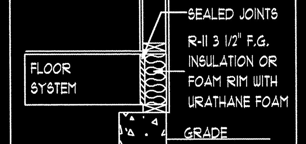
90 Dewpoint location at 37.5 Degrees = Center of foam Interior design = 70 degrees F with 30% RH (warm air = Positive pressure) 2 x 10 rim R = 1 per inch or R-2 Foam Insul. R =8 Ext. design temp = -20 Degrees F (Cold air = Negative pressure) Total R Value = 10 Delta T = 90 See Dew Point Calculations Below R-8 (Foam insulation) Divided by 10 (Total R Value) Multiplied by 90 (Delta T) = Temperature change from one side of foam to other side of foam. Ex. (8/10 x 90 = 72 Degrees temperature Change) The temperature between the foam insulation and the 2 x 10 rim is now at 52 Degrees. ( = 52) The dew point temperature for a building with a interior temp of 70 degrees F and a interior RH of 30% is 37.5 degrees. (see Psychrometric Chart) This is the condensation point in this assembly. If moisture condenses there how will it get out or dry out. Remember it will condensate to the first plane or surface to the cold side. Heat and moisture always flow from warm to cold.
91 Exceptions: 1. Foundation walls enclosing unconditioned spaces shall meet this requirement unless the floor overhead is insulated in accordance with Section N Permanent wood foundations shall meet the requirements of R Frost protected shallow foundations shall meet the requirements of R Insulating concrete form materials shall meet the requirements of Section R611.
92 Basement foundation and crawl space walls. Basement foundation and crawl space walls shall be insulated from the top of the foundation wall down to the top of the footing or from the top edge of the interior wall to the top of the slab if insulation is on the interior.
93 Slab-on-grade and basement walkout foundation walls.
94 Slab-on-grade and basement walkout foundation walls. Insulation shall extend to the design frost line or top of footing whichever is less.
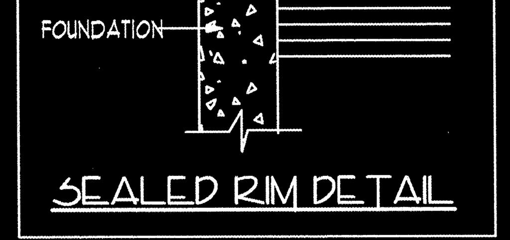
95 Slab-on-grade and basement walkout foundation walls. Insulation shall extend to the design frost line or top of footing whichever is less. The top edge of the insulation installed between the exterior wall and the edge of the interior slab shall be permitted to be cut at a 45-degree angle away from the exterior wall.
96 Slab-on-grade and basement walkout foundation walls. Insulation shall extend to the design frost line or top of footing whichever is less. The top edge of the insulation installed between the exterior wall and the edge of the interior slab shall be permitted to be cut at a 45-degree angle away from the exterior wall. Slab-edge insulation is not required in jurisdictions designated by the code official as having termite infestation.
97 Foundation wall and rim joist area thermal insulation requirements. The foundation wall system and rim joist area shall have an insulating layer with minimum thermal properties as required in this section. The insulation layer must be a minimum R-10 in accordance with Table N
98 Exception The foundation wall system and rim joist area shall have an insulating layer with minimum thermal properties as required in this section. The insulation layer must be a minimum R-10 in accordance with Table N In the Southern Zone, the foundation and rim joist area insulation may be reduced to a minimum of an R-5 if
99 Exception The foundation wall system and rim joist area shall have an insulating layer with minimum thermal properties as required in this section. The insulation layer must be a minimum R-10 in accordance with Table N In the Southern Zone, the foundation and rim joist area insulation may be reduced to a minimum of an R-5 if 1. The insulation is located on the exterior or is integral to the foundation wall; and
100 Exception The foundation wall system and rim joist area shall have an insulating layer with minimum thermal properties as required in this section. The insulation layer must be a minimum R-10 in accordance with Table N In the Southern Zone, the foundation and rim joist area insulation may be reduced to a minimum of an R-5 if 1. The insulation is located on the exterior or is integral to the foundation wall; and 2. An additional R-5 insulation is added to the minimum attic R-value level; and
101 Exception The foundation wall system and rim joist area shall have an insulating layer with minimum thermal properties as required in this section. The insulation layer must be a minimum R-10 in accordance with Table N In the Southern Zone, the foundation and rim joist area insulation may be reduced to a minimum of an R-5 if 1. The insulation is located on the exterior or is integral to the foundation wall; and 2. An additional R-5 insulation is added to the minimum attic R-value level; and. 3. The heating system meets the minimum efficiency ratings in Table N ; and
102 Table HVAC System Minimum Efficiency Requirement to Qualify for R-5 Exterior Insulation in the Southern Zone Heating System Type Minimum Efficiency Rating AFUE HSPF Furnace, Gas or Oil Fired 90% N/A Boiler, Gas or Oil Fired 85% N/A Heat Pump, Split Systems N/A 8.0 Heat Pump, Single Package or Equipment (including gas/electric package units) N/A 7.6
103 Exception The foundation wall system and rim joist area shall have an insulating layer with minimum thermal properties as required in this section. The insulation layer must be a minimum R-10 in accordance with Table N In the Southern Zone, the foundation and rim joist area insulation may be reduced to a minimum of an R-5 if 1. The insulation is located on the exterior or is integral to the foundation wall; and 2. An additional R-5 insulation is added to the minimum attic R-value level; and 3. The heating system meets the minimum efficiency ratings in Table N ; and 4. A minimum of a 6 inch energy heel is used for the roof framing and/or truss system.
104 Requirements for Integral foundation insulation systems An insulation assembly installed integral to the foundation walls shall be manufactured for its intended use and installed according to the manufacturer's specifications.
105 Decision Tree for foundation Insulation in the Residential Energy Code Proposed home Foundation Reqmt s Depending on Foundation Type Integrally insulated Foundation Mandatory items Exterior insulated Foundation Mandatory items Interior insulated Foundation Mandatory items Type of insulation Used and its Reqmt,s for use Type of insulation Used and its Reqmt s for use Reqmt s specific to insulation type (several types) Note: This is not a complicated process. It is very prescriptive. The builder shall decide where they want to insulate the foundation and what product they are going to use and follow the code, including code sections, ASTM Standards etc
106
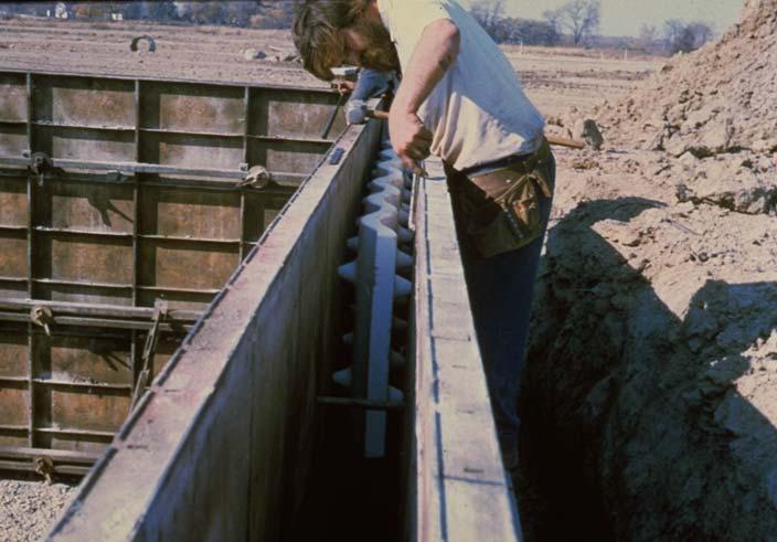
107 Foam Insulation that meets the requirements for R-Value and Perm rating Exterior concrete meets the requirement for protection of the foam to a point 6 inches below grade Interior concrete meets the requirement for thermal barrier and the additional concrete on the warm in winter side can be used as additional R-value Waterproofing or Damproofing Required in accordance with Chapter 4 of the IRC Footing
108
109 Requirements for Exterior foundation insulation requirements
110 Decision Tree for foundation Insulation in the Residential Energy Code Proposed home Foundation Reqmt s Depending on Foundation Type Integrally insulated Foundation Mandatory items Exterior insulated Foundation Mandatory items Interior insulated Foundation Mandatory items Type of insulation Used and its Reqmt,s for use Type of insulation Used and its Reqmt s for use Reqmt s specific to insulation type (several types) Note: This is not a complicated process. It is very prescriptive. The builder shall decide where they want to insulate the foundation and what product they are going to use and follow the code, including code sections, ASTM Standards etc
111 1. Shall be of water resistant materials manufactured for its intended use;
112 1. Shall be of water resistant materials manufactured for its intended use; 2. Installed according to the manufacturer's specifications;
113 1. Shall be of water resistant materials manufactured for its intended use; 2. Installed according to the manufacturer's specifications; 3. Shall comply with either ASTM C578, C612 or C1029 as applicable and;
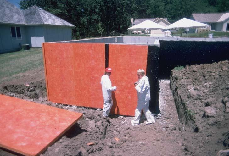
114 Exterior foundation insulation 1. Shall be of water resistant materials manufactured for its intended use; 2. Installed according to the manufacturer's specifications; 3. Shall comply with either ASTM C578, C612 or C1029 as applicable and; 4. Shall have a rigid, opaque and weather-resistant protective covering to prevent the degradation of the insulation s thermal performance. The protective covering shall cover the exposed exterior insulation and extend a minimum of 6 inches (152 mm) below grade. The insulation and protective covering system shall be flashed in accordance with the IRC Section R703.8.
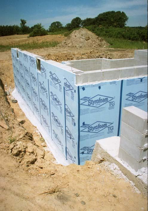
115 Exterior Foundation Insulation Foam Insulation that meets the requirements for R-Value and is approved for exterior use Exterior covering meeting the requirement for protection of the foam to a point 6 inches below grade Concrete wall meets the requirement for thermal barrier Waterproofing or Damproofing Required in accordance with Chapter 4 of the IRC Footing
116 Decision Tree for foundation Insulation in the Residential Energy Code Proposed home Foundation Reqmt s Depending on Foundation Type Integrally insulated Foundation Mandatory items Exterior insulated Foundation Mandatory items Interior insulated Foundation Mandatory items Type of insulation Used and its Reqmt,s for use Type of insulation Used and its Reqmt s for use Reqmt s specific to insulation type (several types) Note: This is not a complicated process. It is very prescriptive. The builder shall decide where they want to insulate the foundation and what product they are going to use and follow the code, including code sections, ASTM Standards etc
117
118
119 Requirements for Interior foundation insulation
120 Decision Tree for foundation Insulation in the Residential Energy Code Proposed home Foundation Reqmt s Depending on Foundation Type Integrally insulated Foundation Mandatory items Exterior insulated Foundation Mandatory items Interior insulated Foundation Mandatory items Type of insulation Used and its Reqmt,s for use Type of insulation Used and its Reqmt s for use Reqmt s specific to insulation type (several types) Note: This is not a complicated process. It is very prescriptive. The builder shall decide where they want to insulate the foundation and what product they are going to use and follow the code, including code sections, ASTM Standards etc
121 Interior foundation insulation 1. Masonry foundation walls shall be drained through the masonry block cores to an approved interior drainage system.
122 Interior Foundation Insulation Masonry foundation walls shall be drained through the masonry block cores to an approved interior drainage system.
123 Interior foundation insulation 1. Masonry foundation walls shall be drained through the masonry block cores to an approved interior drainage system. 2. If a frame wall is installed it shall not be in direct contact with the foundation wall, unless that interior side of the foundation wall has been waterproofed.
124 Interior Foundation Insulation Masonry foundation walls shall be drained through the masonry block cores to an approved interior drainage system. If a frame wall is installed it shall not be in direct contact with the foundation wall, unless that interior side of the foundation wall has been waterproofed.
125 Interior foundation insulation 1. Masonry foundation walls shall be drained through the masonry block cores to an approved interior drainage system. 2. If a frame wall is installed it shall not be in direct contact with the foundation wall, unless that interior side of the foundation wall has been waterproofed. 3. Comply with the interior air barrier requirements in N
126 Interior Foundation Insulation Warm Side Vapor and Air barrier Masonry foundation walls shall be drained through the masonry block cores to an approved interior drainage system. If a frame wall is installed it shall not be in direct contact with the foundation wall, unless that interior side of the foundation wall has been waterproofed.
127 Interior Foundation Insulation Insulation that meets the requirements for R- Value Warm Side vapor and Air barrier Masonry foundation walls shall be drained through the masonry block cores to an approved interior drainage system. If a frame wall is installed it shall not be in direct contact with the foundation wall, unless that interior side of the foundation wall has been waterproofed. Waterproofing or Damproofing Required in accordance with Chapter 4 of the IRC Footing
128 Interior foundation insulation requirements 1. Masonry foundation walls shall be drained through the masonry block cores to an approved interior drainage system. 2. If a frame wall is installed it shall not be in direct contact with the foundation wall, unless that interior side of the foundation wall has been waterproofed. 3. Comply with the interior air barrier requirements in N Comply with section N , N , N , or N
129 Decision Tree for foundation Insulation in the Residential Energy Code Proposed home Foundation Reqmt s Depending on Foundation Type Integrally insulated Foundation Mandatory items Exterior insulated Foundation Mandatory items Interior insulated Foundation Mandatory items Type of insulation Used and its Reqmt,s for use Type of insulation Used and its Reqmt s for use Reqmt s specific to insulation type (several types) Note: This is not a complicated process. It is very prescriptive. The builder shall decide where they want to insulate the foundation and what product they are going to use and follow the code, including code sections, ASTM Standards etc
130 Rigid interior insulation N Either ASTM C 578 or ASTM C 1289.
131 Rigid interior insulation N Either ASTM C 578 or ASTM C Dampproofing, waterproofing, or a water repellant shall be applied to the exposed above grade foundation walls or a layer of dampproofing or waterproofing shall be installed on the entire inside surface of the foundation wall. Water repellant materials shall comply with ASTM E 514 with 90% or greater reduction in water permeance when compared to an untreated sample.
132 Rigid Interior Foundation Insulation N Damproofing, waterproofing or water repellent above grade Grade level waterproofing or damproofing with parging
133 Rigid Interior Foundation Insulation N Installation requirements a. Must be in contact with the foundation wall surface b. Vertical edges shall be sealed with acoustic sealant c. All interior joints, edges, and penetrations shall be sealed against air and water vapor penetration. d. Horizontally continuous acoustic sealant between the foundation wall and the insulation at the top of the foundation wall. e. Horizontally continuous acoustic sealant between the basement floor and the bottom insulation edge. Damproofing, waterproofing or water repelent above grade Grade level
134 Rigid Interior Foundation Insulation N Installation requirements The insulation shall not be penetrated by the placement of utilities or by fasteners or connectors used to install a frame wall. Damproofing, waterproofing or water repelent above grade Grade level
135 Decision Tree for foundation Insulation in the Residential Energy Code Proposed home Foundation Reqmt s Depending on Foundation Type Integrally insulated Foundation Mandatory items Exterior insulated Foundation Mandatory items Interior insulated Foundation Mandatory items Type of insulation Used and its Reqmt,s for use Type of insulation Used and its Reqmt s for use Reqmt s specific to insulation type (several types) Note: This is not a complicated process. It is very prescriptive. The builder shall decide where they want to insulate the foundation and what product they are going to use and follow the code, including code sections, ASTM Standards etc
136 Spray applied interior insulation N Closed cell polyurethane
137 Spray applied interior insulation N Closed cell polyurethane a. ASTM C 1029 compliant with a permeance not greater than 1 in accordance with ASTM E 96 procedure A.
138 Spray applied interior insulation N Closed cell polyurethane a. ASTM C 1029 compliant with a permeance not greater than 1 in accordance with ASTM E 96 procedure A. b. Sprayed directly onto the foundation wall surface. There must be a 1 minimum gap between the foundation wall surface and any framing.
139 Interior Spray applied interior insulation N Insulation that meets the requirements for R- Value Foam may become the Warm Side vapor and Air barrier If a frame wall is installed it shall not be in direct contact with the foundation wall
140 Interior Spray applied interior insulation N Insulation that meets the requirements for R- Value Foam may become the Warm Side vapor and Air barrier If a frame wall is installed it shall not be in direct contact with the foundation wall The insulation shall not be penetrated by the placement of utilities. Through penetrations shall be sealed
141 Spray applied interior insulation N ½ pound free rise open cell foam
142 Spray applied interior insulation N ½ pound free rise open cell foam a. Sprayed directly onto the foundation wall surface. There must be a 1 minimum gap between the foundation wall surface and any framing.
143 Interior Spray applied interior insulation N Insulation that meets the requirements for R- Value Foam may become the Warm Side Air barrier If a frame wall is installed it shall not be in direct contact with the foundation wall
144 Interior Spray applied interior insulation N Insulation that meets the requirements for R- Value Foam may become the Warm Side vapor and Air barrier If a frame wall is installed it shall not be in direct contact with the foundation wall The insulation shall not be penetrated by the placement of utilities. Through penetrations shall be sealed
145 Semi-rigid interior insulation N
146 Decision Tree for foundation Insulation in the Residential Energy Code Proposed home Foundation Reqmt s Depending on Foundation Type Integrally insulated Foundation Mandatory items Exterior insulated Foundation Mandatory items Interior insulated Foundation Mandatory items Type of insulation Used and its Reqmt,s for use Type of insulation Used and its Reqmt s for use Reqmt s specific to insulation type (several types) Note: This is not a complicated process. It is very prescriptive. The builder shall decide where they want to insulate the foundation and what product they are going to use and follow the code, including code sections, ASTM Standards etc
147 Semi-rigid interior insulation N ASTM C1621 with a maximum permeance of 1.1 per inch.
148 Semi-rigid interior insulation N ASTM C1621 with a maximum permeance of 1.1 per inch. 2. Must have a minimum density of 1.3 pcf and have a fungal resistance per ASTM C1338.
149 Semi-Rigid Interior Foundation Insulation N Installation requirements a. Must be in contact with the foundation wall surface b. Vertical edges shall be sealed with acoustic sealant c. All interior joints, edges, and penetrations shall be sealed against air and water vapor penetration. d. Horizontally continuous acoustic sealant between the foundation wall and the insulation at the top of the foundation wall. e. Horizontally continuous acoustic sealant between the basement floor and the bottom insulation edge.
150 Unfaced fiberglass batt interior insulation
151 Decision Tree for foundation Insulation in the Residential Energy Code Proposed home Foundation Reqmt s Depending on Foundation Type Integrally insulated Foundation Mandatory items Exterior insulated Foundation Mandatory items Interior insulated Foundation Mandatory items Type of insulation Used and its Reqmt,s for use Type of insulation Used and its Reqmt s for use Reqmt s specific to insulation type (several types) Note: This is not a complicated process. It is very prescriptive. The builder shall decide where they want to insulate the foundation and what product they are going to use and follow the code, including code sections, ASTM Standards etc
152 Unfaced fiberglass batt interior insulation 1. Waterproofing shall be applied to the entire inside surface of the foundation wall.
153 Unfaced fiberglass Interior Foundation Insulation N Damproofing, waterproofing or water repellent above grade. Grade level Waterproofing shall be applied to the entire inside surface of the foundation wall
154 Unfaced fiberglass batt interior insulation 1. Waterproofing shall be applied to the entire inside surface of the foundation wall. 2. The top and bottom plates must be air sealed to the foundation wall surface and the basement floor.
155 Unfaced fiberglass Foundation Insulation N The top and bottom plates must be air sealed to the foundation wall surface and the basement floor.
156 Unfaced fiberglass Foundation Insulation N In addition an air barrier material and vapor retarder material with a minimum a. permeance of at least 1 in accordance with ASTM E 96 procedure A. a. Air sealed to the framing with construction adhesive or equivalent at the top and bottom plates and where the adjacent wall is insulated, and b. Air sealed utility boxes and other penetrations, and c. All seams shall be overlapped at least 6 inches and sealed with compatible sealing tape or equivalent. Waterproofing shall be applied to the entire inside surface of the foundation wall The top and bottom plates must be air sealed to the foundation wall surface and the basement floor.
157 Unfaced fiberglass batt interior insulation 1. Waterproofing shall be applied to the entire inside surface of the foundation wall. 2. The top and bottom plates must be air sealed to the foundation wall surface and the basement floor. 3. In addition an air barrier material and vapor retarder material with a minimum a permeance of at least 1 in accordance with ASTM E 96 procedure A. a. Air sealed to the framing with construction adhesive or equivalent at the top and bottom plates and where the adjacent wall is insulated, and b. Air sealed utility boxes and other penetrations, and c. All seams shall be overlapped at least 6 inches and sealed with compatible sealing tape or equivalent. d. Up to R-13 batts are allowed.
158 Foundation Wall Insulation Performance Option
159 Decision Tree for foundation Insulation in the Residential Energy Code Proposed home Foundation Reqmt s Depending on Foundation Type Integrally insulated Foundation Mandatory items Exterior insulated Foundation Mandatory items Interior insulated Foundation Mandatory items Type of insulation Used and its Reqmt,s for use Type of insulation Used and its Reqmt s for use Reqmt s specific to insulation type (several types) Note: This is not a complicated process, for the builder. However for someone else it may be
160 Foundation Wall Insulation Performance Option Insulated foundation systems designed and installed under the performance option shall meet the requirements of this section.
161 Water separation plane The foundation shall be designed and built to have a continuous water separation plane between the interior and exterior. The interior side of the water separation plane must:
162 Water separation plane 1. Have a stable annual wetting/drying cycle whereby foundation wall system water (solid, liquid and vapor) transport processes produce no net accumulation of ice or water over a full calendar year and the foundation wall system is free of adsorbed water for at least 4 months over a full calendar year;
163 Water separation plane 1. Have a stable annual wetting/drying cycle whereby foundation wall system water (solid, liquid and vapor) transport processes produce no net accumulation of ice or water over a full calendar year and the foundation wall system is free of adsorbed water for at least 4 months over a full calendar year; 2.Prevent conditions of moisture and temperature to prevail for a time period favorable to mold growth for the materials used; and
164 Water separation plane 1. Have a stable annual wetting/drying cycle whereby foundation wall system water (solid, liquid and vapor) transport processes produce no net accumulation of ice or water over a full calendar year and the foundation wall system is free of adsorbed water for at least 4 months over a full calendar year; 2.Prevent conditions of moisture and temperature to prevail for a time period favorable to mold growth for the materials used; and 3.Prevent liquid water from the foundation wall system reaching the foundation floor system at any time during a full calendar year.
165 Documentation The foundation insulation system designer shall provide documentation certified by a professional engineer registered in Minnesota demonstrating how the requirements of this section are fulfilled. The foundation insulation system designer shall also specify the design conditions for the wall and the design conditions for the interior space for which the water separation plane will meet the requirements of this section. The foundation insulation system designer shall provide a label disclosing these design conditions and the label shall be posted in accordance with N
166 Installation The water separation plane shall be designed and installed to prevent external liquid or capillary water flow across it after the foundation is backfilled.
167 Foundation air barrier. The foundation insulation system shall be designed and installed to have a foundation air barrier system between the interior and the exterior.
168 Foundation air barrier. The foundation insulation system shall be designed and installed to have a foundation air barrier system between the interior and the exterior. The foundation air barrier system must be a material or combination of materials that is continuous with all joints sealed and is durable for the intended application.
169 Foundation air barrier. The foundation insulation system shall be designed and installed to have a foundation air barrier system between the interior and the exterior. The foundation air barrier system must be a material or combination of materials that is continuous with all joints sealed and is durable for the intended application. Material used for the foundation air barrier system must have an air permeability not to exceed ft3/min.ft2 under a pressure differential of 0.3 in. water (1.57psf) (0.02 L/s.m2 at 75Pa) as determined by either commonly accepted engineering tables or by being labeled by the manufacturer as having these values when tested in accordance with ASTM E2178.
170 FENESTRATION.
171 Glazed fenestration exemption Up to 15 ft 2 of glazed fenestration per dwelling unit shall be permitted to be exempt from U-factor requirements in Section N
172 Opaque door exemption One opaque door assembly is exempted from the U-factor requirements in Section N1102.1

173 Thermally isolated sunroom U- factor New windows and doors separating the sunroom from conditioned space shall meet the building thermal envelope requirements.
174 Replacement Fenestration Where some or all of an existing fenestration unit is replaced with a new fenestration product, including frame, sash, and glazing, the replacement fenestration unit shall meet the applicable requirements for U-factors found in Tables N1102.1, unless exempt under Section
175 Ventilation
176 Ventilation Minnesota Rules, Chapter 1322, Residential Energy Code 1. Ventilation Overview -What is ventilation -Why ventilate -How much should we ventilate 2. Mechanical Ventilation Systems -Total and continuous ventilation rates -Ventilation System Requirements (3 types) Exhaust only Balanced Other methods 3. Air distribution/circulation 4. Insulation, labeling, documentation
177 Ventilation Systems-Overview Goals of Mechanical Ventilation To maintain good indoor air quality To control indoor moisture
178 Ventilation Systems-Overview ASHRAE Acceptable indoor air quality: air in which there are no known contaminants at harmful concentrations as determined by cognizant authorities and with which a substantial majority (80% or more) of the people exposed do not express dissatisfaction.
179 Ventilation Systems When to Ventilate? Primarily when the home is occupied May need to continue after or purge before
180 Ventilation Systems When to Ventilate? Primarily when the home is occupied May need to continue after or purge before Where to Ventilate? Ideally where the pollutants are concentrated Remove point source pollutants immediately Use general ventilation for disperse pollutants
181 Overview- What is Ventilation? The process of supplying air to or removing air from a space for the purpose of controlling air contaminant levels, humidity, or temperature within the space. In with the good! Out with the bad!
182 Overview- Ventilation Systems Why Ventilate? People pollutants human respiration, body odors water vapor Building pollutants VOCs, Combustion gases, radon water vapor Activity pollutants VOCs, odors water vapor
183 Overview-Ventilation Systems Types of Air Exchange in Houses Infiltration/Exfiltration Natural ventilation Chimneys Exhaust devices Mechanical ventilation
184 Why Ventilate?
185 IAQ Solutions - HUMIDITY CONTROL Why Manage Humidity? Moisture + Source of Spores Constant Temperature ( F) + + = Prerequisites for Microbial Growth
186 OVERVIEW- HUMIDITY CONTROL ASHRAE-recommended Comfort Problems Organic Growth Percent Relative Humidity, % RH
187 Overview- Ventilation Systems How Much to Ventilate, considering:? Moisture generation rates people building Other pollutants type of pollutant source strength Occupant sensitivity Continuous ventilation
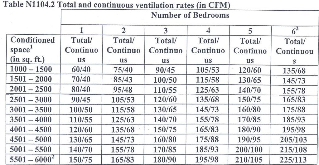
188 Overview-Ventilation Systems How Much to Ventilate? Chapter 1322: Total ventilation rate: shall provide sufficient outdoor air = total ventilation rate average, for each one hour period in accordance with Table N1104.2, or equation Equation 11-1 Total ventilation rate (CFM) = (0.02 x square feet of conditioned space) + (15 x (number of bedrooms +1)). Includes the basement but excludes conditioned crawl spaces.
189 Overview-Ventilation Systems Equation 11-1 Total ventilation rate (CFM) = (0.02 x square feet of conditioned space) + (15 x (number of bedrooms +1)). Example 1: 2300 square feet of conditioned space house Conditioned space = An area, room or space being heated or cooled by any equipment or appliance. 3 bedrooms.02 x square feet of conditioned space =.02 x 2300 = 46 CFM Number of bedrooms (3) + 1 = 4 15 x 4 = 60 CFM Total ventilation rate (CFM) = 46 CFM + 60 CFM = 106 CFM
190
191
192
193
194 Overview-Ventilation Systems Continuous Ventilation: N : a minimum of 50% of the total ventilation rate, but not less than 40 CFM, on a continuous rate average for each one hour period in accordance with Table N or Equation Equation 11-2: Continuous ventilation (CFM)= total ventilation rate /2.
195
196 Overview-Ventilation Systems Total Ventilation : equation 11-1 total ventilation rate = 106 CFM and Table N total ventilation rate = 110 CFM. Continuous ventilation rate = 53 CFM (if equation 11-2 is used) or 55 CFM = 55 CFM if table N is used.
197 Supplemental Ventilation Kitchen Exhaust Bathroom Exhaust ETC.
198 Ventilation Systems Required ventilation rate Example 2 (.02 x square feet of conditioned space + ( 15x (number of bedrooms +1)) = Total Ventilation Rate Example: 4 bedroom, 2 bathroom, 2,000 sq.ft. house (4 Bedrooms + 1) X 15 (cfm) 5 X 15 =75 + (0.02 (cfm) X 2000 sq.ft.) cfm 115 cfm
199 Continuous Ventilation Rate 50% of Total Ventilation Rate Example: 115 cfm 2 = 57.5 cfm > 60 cfm Draft rule Chapter 1322 N
200
201
202
203 Ventilation Systems Required ventilation rate Example 3 (.02 x square feet of conditioned space) + (15 x (number of bedrooms +1)) = Total Ventilation Rate 6 bedroom, 3 bathroom, 5,000 sq.ft. house (6 Bedrooms + 1) X 15 (cfm) 7 X 15 =105 + (0.02 (cfm) X 5000 sq.ft.) =
204
205
206
207 Ventilation Systems Required ventilation rate Example 4 (.02 X square feet of conditioned space) + (15 x (number of bedrooms +1))= Total Ventilation Rate Example: 6 bedroom, 3 bathroom, 7,000 sq.ft. house (6 Bedrooms + 1) X 15 (cfm) 7 X 15 =105 + (0.02 (cfm) X 7000 sq.ft.) cfm
208
209 Sub-script 2 to the table If conditioned space exceeds 6000 sq. ft. or there are more than 6 bedrooms, use Equation 11-1 from section N to calculate total ventilation rate.
210 Ventilation Systems Framework for Mechanical Ventilation Quantity and location of exhaust (stale, moist) air Quantity and location of supply (fresh, outdoor) air Pressure imbalances (unbalanced exhaust & supply) Internal distribution/circulation patterns Controls
211 Overview-Ventilation Systems N Ventilation system requirements. The mechanical ventilation system shall be one of 3 types: 1. Exhaust in accordance with N (Continuous ventilation section). 2. Balanced, and HRV/ERV in accordance with N Other method in accordance with N
212 Overview-Ventilation Systems N Exhaust Systems. Fans used to comply with the continuous ventilation part of the mechanical ventilation system shall:
213 Overview-Ventilation Systems N Exhaust Systems. Fans used to comply with the continuous ventilation part of the mechanical ventilation system shall: 1. Meet minimum continuous rate in N
214 Overview-Ventilation Systems N Exhaust Systems. Fans used to comply with the continuous ventilation part of the mechanical ventilation system shall: 1. Meet minimum continuous rate in N Designed and certified by equipment manufacturer as capable of continuous operation at rated CFM
215 Overview-Ventilation Systems N Exhaust Systems. Fans used to comply with the continuous ventilation part of the mechanical ventilation system shall: 1. Meet minimum continuous rate in N Designed and certified by equipment manufacturer as capable of continuous operation at rated CFM 3. Have a 1.0 sone maximum per HVI Standard 915 for surface mounted fans
216 Overview-Ventilation Systems N Exhaust Systems. Fans used to comply with the continuous ventilation part of the mechanical ventilation system shall: 1. Meet minimum continuous rate in N Designed and certified by equipment manufacturer as capable of continuous operation at rated CFM 3. Have a 1.0 sone maximum per HBI Standard 915 for surface mounted fans 4. Be permitted to use a required overcurrent protection device as a disconnect per the NEC.
217 Overview-Ventilation Systems N Exhaust Systems. Fans used to comply with the continuous ventilation part of the mechanical ventilation system shall: 1. Meet minimum continuous rate in N Designed and certified by equipment manufacturer as capable of continuous operation at rated CFM 3. Have a 1.0 sone maximum per HBI Standard 915 for surface mounted fans 4. Be permitted to use a required overcurrent protection device as a disconnect per the NEC. 5. Comply with the MN Mechanical Code 1346 which may require additional makeup air.
218 Ventilation System Requirements Exhaust Systems Exhaust Fans the Continuous Ventilation Rate Plus supplemental/intermittent ventilation system Make up air into home? Note: Surface mounted fan runs continuously at 1 sone fan In-line fan (outside conditioned space) and intermittent fans run continuously at 2.5 sone fan
219 Exhaust-only systems 1. Decentralized fans in baths, kitchen, laundry, etc. 2. Centralized exhaust system with or without heat recovery
220 Decentralized Exhaust-Only Point Source Approach (Example using a single fan)

221 Decentralized Exhaust-Only Point Source Approach

222 Decentralized Exhaust-Only Point Source Approach Flex Duct installations shall be stretched tight with no sags and excess duct cut off to allow for less static pressure loss and a more effective system.
223 Centralized Exhaust-Only Point Source Approach (Example using a dedicated exhaust Unit)
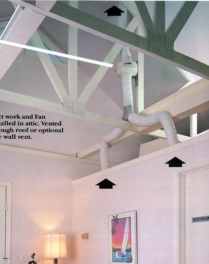
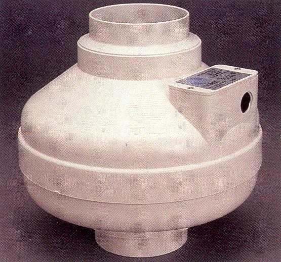
224 Centralized Exhaust-Only Point Source Approach
225 Ventilation Systems Balanced systems integrated supply and exhaust system HRV/ERV most common system
226 Ventilation Systems Balanced systems integrated supply and exhaust system separate supply and exhaust fans
227 Mechanical ventilation is required: Balanced ventilation systems Energy Recovery Ventilator (ERV) Heat Recovery Ventilator (HRV) Fans
228 N Balanced, and HRV/ERV Systems. Shall meet either: 1. The requirements of HVI Standard 920, 72 hour minus 13 F cold weather test, or 2. Certified by a licensed professional engineer and installed per manufacturers installation instructions.
229 Balanced Ventilation Volume Source Approach
230 Balanced Ventilation Energy Recovery Ventilator

231 Balanced Ventilation Heat Recovery Ventilator

232 Heat Recovery Ventilator


233 Heat Recovery Ventilator Filter Exhaust Air Supply Air Outdoor Air Return Air Filter Heat Exchanger Filter


234 Heat Recovery Ventilator 1. Transfers heat by conduction

235 HRV Defrost Operation Recirculation damper opens Supply Air Supply damper closes Return Air Heat Exchanger


236 Energy Recovery Ventilator 1. Transfers heat by conduction 2. Transfers humidity using hygroscopic resin
237 Ventilation System Requirements (Example) Balanced Systems (HRV or ERV) Provides an average of 60 cfm Provide (60 cfm X 60 min) = 3,600 cfh
238 Ventilation System Requirements Exhaust Systems Balanced Systems (ERV) Provides an average of 60 cfm Provide (60 cfm X 60 min) = 3,600 cfh 120 cfm for 30 minutes (120 X 30 = 3,600) 180 cfm for 20 minutes (180 X 20 = 3,600) 240 cfm for 15 minutes (240 X 15 = 3,600)

239 Proportional Timer Turns unit on and off a percentage of each hour
240 Overview-Ventilation Systems N Other methods. Any mechanical ventilation system consisting of exhaust fans, supply fans or combination of both (that comply with N1104) shall be allowed.
241 Other Methods-complies with N1104 Separate Exhaust and Supply
242 Installation Requirements Installed in accordance with MN Rule 1346
243 Air distribution/circulation 4 conditions Outdoor air shall be delivered to each habitable space by: 1. A forced air circulation system (Furnace)
244 Air distribution/circulation 4 conditions Outdoor air shall be delivered to each habitable space by: 1. A forced air circulation system (Furnace) 2. Separate duct system
245 Air distribution/circulation 4 conditions Outdoor air shall be delivered to each habitable space by: 1. A forced air circulation system (Furnace) 2. Separate duct system 3. Individual inlets
246 Not ducted through Furnace
247 Air distribution/circulation 4 conditions Outdoor air shall be delivered to each habitable space by: 1. A forced air circulation system (Furnace) 2. Separate duct system 3. Individual inlets 4. Passive opening
248 Air distribution/circulation First condition: using forced air circulation system Outdoor air shall be delivered to each habitable space by: 1. A forced air circulation system (Furnace) Outdoor air in NOT ducted to the forced air system Outdoor air IS ducted to the forced air system
249 Air distribution/circulation Outdoor air shall be delivered to each habitable space by: 1. A forced air circulation system (Furnace) (a) When an outdoor air supply is not ducted to the forced air system, controls shall be installed to allow the forced air system to provide an average circulation flow rate each hour, of not less than 0.15 cfm/sq.ft. of the conditioned floor area.
250 Not ducted through Furnace ERV or HRV
251 Air distribution/circulation Outdoor air shall be delivered to each habitable space by: 1. A forced air circulation system (Furnace) (b) When an outdoor air supply IS ducted to the forced air system, it shall be tempered so that the mixed air temperature shall be no less than 60 degrees Fahrenheit or the heating equipment manufacturers installation instruction, and controls shall be installed.not less than cfm / ft ^2 of conditioned floor area.
252 Intake openings Exterior air intake openings shall be located in accordance Minnesota Rules Chapter 1346.
253 Filtration All mechanically supplied outdoor air shall have a filter with a designated minimum efficiency of MERV 4 (i.e. good furnace filter) The filter shall be located on the inlet of the appliance and shall be installed to be readily accessible and facilitate regular service.
254 Controls. Mechanical ventilation system controls shall be provided in accordance with the following: 1. If required by the equipment (i.e. HRV or ERV) manufacturer s installation instructions, controls shall be installed to ensure that the forced air circulation system is operating whenever the mechanical ventilation system is operating.
255 Controls. Mechanical ventilation system controls (N ) shall be provided in accordance with the following: 2. Controls shall be installed to ensure that whenever the mechanical ventilation system is operating, the forced air circulation system provides indirect circulation of 0.15 cfm per square foot of conditioned floor area or direct distribution of cfm per square foot of conditioned floor area.
256 Controls. Mechanical ventilation system controls (N ) shall be provided in accordance with the following: 3. If the mechanical ventilation system is not designed to operate whenever the forced air circulation system is operating, the mechanical ventilation system shall incorporate an accessible backflow damper to prevent flow from the outside when the mechanical ventilation system is off.
257 Controls. Mechanical ventilation system controls (N ) shall be provided in accordance with the following: 4. Controls shall be compatible with the mechanical ventilation system.
258 Controls. Mechanical ventilation system controls (N ) shall be provided in accordance with the following: 5. Controls shall be installed to operate the mechanical ventilation system as designed.
259 Controls. Mechanical ventilation system controls (N ) shall be provided in accordance with the following: 6. Controls shall be readily accessible to occupants and shall be labeled to indicate their function.
260 Controls. Mechanical ventilation system controls (N ) shall be provided in accordance with the following: 7. If a switch is used to control the continuous ventilation system, it can be centrally or remotely located. If remotely located, it shall NOT be in a bath or toilet room. If centrally located, it shall be properly labeled and lighted when the system is on. If remotely located, there shall be a lighted status indicator in a central location that will be lighted when the system is on.

261 Push Button Switch
262 Labeling The outdoor air intake and exhaust air outlet shall include a permanent, weather resistant identification label stating: OUTDOOR AIR INTAKE or EXHAUST AIR OUTLET.
263 Labeling The outdoor air intake and exhaust air outlet shall include a permanent, weather resistant identification label stating: Controls provided for continuous and intermittent ventilation shall be provided with a label stating VENTILATION SYSTEM or VENTILATION FAN or INTERMITTENT FAN or ventilation symbols, as appropriate.

264 Labeling OUTDOOR AIR INTAKE EXHAUST AIR OUTLET
265 Documentation (ALL) Mechanical ventilation systems shall be provided with documentation that includes proper operation and maintenance instructions and a warning regarding potential problems if the system is not operated and maintained. Bathroom fans ERV s & HRV s Furnaces Other equipment
266 Documentation A permanent warning label shall be affixed to mechanical ventilation systems if it is readily accessible. If the mechanical ventilation system is not readily accessible, the documentation shall be in a conspicuous readily accessible location. (i.e. on the furnace or ERV)
267 Changing Design Conditions Summer Db/Wb ºF Winter Db ºF City Albert Lea 87/72 85/ Alexandria 88/72 86/ Bemidji 85/69 84/ Brainerd 87/71 86/ Duluth 82/68 81/ Faribault 88/72 86/ Fergus Falls 88/72 86/ Virginia 83/72-25 International Falls 83/68 83/ Mankato 88/72 86/ Minneapolis/St. Paul 89/73 88/ Rochester 87/72 85/ St. Cloud 88/72 86/ Willmar 88/72 85/ Winona 88/73 88/
268 Changing Design Conditions Summer Db/Wb ºF Winter Db ºF City Aitkin 82/72-24 Cloquet 82/68-20 Crookston 84/70-27 Ely 82/68-29 Eveleth 82/68-26 Hibbing 82/68-19 Montevideo 86/72-17 Mora 84/70-21 Morris 84/72-21 New Ulm 87/73-15 Owatonna 86/73-16 Pequot Lake 84/68-23 Pipestone 85/73-15 Redwood Falls 89/73-17 Roseau 82/70-29 Thief River 82/68-25 Tofte 75/61-14 Warroad 83/67-29 Wheaton 84/71-20 Worthington 84/71-14
269 Residential Thermostats At least one thermostat shall be provided for each separate heating and cooling system Does not require a programmable stat!
270 Duct Insulation Ducts shall be insulated in accordance with Minnesota Rule Chapter 1346

271 Residential Duct Insulation R-3.5

272 Duct Sealing!
273 Supply Ducts Supply ducts shall be continuously ducted from the point of origin to the point of discharge... building framing cavities and building components shall not be used as supply ducts.
274 Domestic Water Piping Insulation A. Cold Water: No insulation required. Exception: 1. Piping within 6 inches of any heating pipes,... and underground piping,... minimum of 1 insulation with... vapor jacket.
275 Domestic Water Piping Insulation B. Hot Water: No insulation required. Exceptions: 1. All recirculating systems on the entire loop with vapor jacket. 2. Underground piping, underground piping,... minimum of 1 insulation with... vapor jacket.
276 HVAC Piping Insulation Hydronic, steam, and condensate piping... insulated in accordance with Minnesota Chapter Rule 1346 and shall have vapor appropriate jacket.
277 HVAC Piping Insulation Hydronic, steam, and condensate piping.. Exceptions: 1. Piping installed within HVAC equipment; or 2. Piping installed in basements, crawl spaces, and cellars.

278 HVAC Piping Insulation!