The need to design for robustness in fire. Ian Burgess
|
|
|
- Molly Stewart
- 5 years ago
- Views:
Transcription
1 The need to design for robustness in fire Ian Burgess
2 Robustness a working definition The ability of a structure to avoid disproportionate collapse when subject to a localised failure Hence: Only structural resistance failure is considered 2


3 Why is it important in fire? Multiple localised structural failures in fire + impact damage. Collapse of the whole structure, including 90% unaffected by fire or impact. Key NIST Post WTC Recommendation Increase structural integrity Develop design tools and modify codes to prevent progressive collapse. 3
4 Steel behaviour at high temperatures Stress (N/mm 2 ) C 200 C 300 C 400 C 500 C 600 C 700 C 800 C Expansion Coeff / C (x 10 5 ) Steel Strain (%) Temperature ( C)
5 Sources of disproportionate collapse
6 6 Multi storey construction: composite buildings
7 7 Multi storey construction: composite buildings
8 8 Multi storey construction: composite buildings
9 9 Whole storey fire
10 10 Whole storey fire
11 Local failures Beam failure Column buckling Connection fracture 11
12 12 Beam failure
13 Consequence of excessive beam deformation Beam/slab deflection does not in itself cause structural failure, unless it causes columns to buckle or joints to fracture. It may cause compartmentation integrity failure which allows fire to spread. 13
14 14 Column buckling
15 Column buckling Initial column loadings. 15
16 Column buckling Column loadings redistribute. May overload other columns. Column buckles. Fire spreads. 16 Possibility of pull-in collapse locally.
17 Column buckling Column loadings redistribute further. Fire spreads. Further column buckles. 17
18 Column buckling Further columns buckle. Frame collapse. 18
19 Column buckling Further columns buckle. Frame collapse. 19
20 Consequences of column buckling in fire Loads are redistributed to adjacent columns similar to column-out scenario in blast-resistant design. A single column collapse may lead to severe local collapse. May be mitigated to some extent by 2-dimensional redistribution via slabs. If these are also affected by temperature-dependent strength reduction there is a high probability of building collapse. Columns should be designed for fire resistance with care. Passive protection is usually required. 20
21 Interactive failure Multi storey fire spread 21
22 Vertical external fire spread E D C B Flames cause windows to break on burning storey (A) and the floor above (B). A 22
23 Vertical external fire spread E D C B FIre propagates on Floor B, spreads through windows to Floor C. A 23
24 Vertical external fire spread E D C FIre propagates on Floor C, spreads through windows to Floor D. B A 24
25 Pull in enhanced buckling of columns E D C B A 25 Heated beams pulling on column Greatly increased effective length Column itself weakened by heating Inward buckling of column. Partial or overall collapse.


26 WTC 1: Observed column pull in WTC 1 exterior columns bowing inward across most of the south face between floors 95 to 98 at am. 26
27 WTC 1: Numerical modelling Perimeter wall analysis found an inward pull force of 27kN at each column at floors 95 to 99, starting 80 minutes after the aircraft impact, caused a maximum inward bowing of 790mm. 27
28 28 Catenary forces on connections WTC 1 and 2 floor trusses
29 Connection force in WTC floor model: ISO834 fire Horizontal reaction (kn) Deflection (mm) Time (min) Time (min) 29
30 Connection force in WTC floor model: ISO834 fire Horizontal reaction (kn) Push out Deflection (mm) Time (min) Time (min) Differential thermal expansion 30
31 Connection force in WTC floor model: ISO834 fire Horizontal reaction (kn) Push out Deflection (mm) Time (min) Time (min) Yield of mid span bottom chord 31
32 Connection force in WTC floor model: ISO834 fire Horizontal reaction (kn) Pull in Deflection (mm) Time (min) Time (min) Yield of mid span bottom chord 32
33 Connection force in WTC floor model: ISO834 fire Horizontal reaction (kn) Pull in Deflection (mm) Time (min) Time (min) Diagonal struts at ends buckle in cascade 33
34 Connection force in WTC floor model: ISO834 fire Horizontal reaction (kn) Pull in Deflection (mm) Time (min) Time (min) Diagonal struts at ends buckle in cascade 34
35 Connection force in WTC floor model: ISO834 fire Horizontal reaction (kn) Pull in Deflection (mm) Time (min) Time (min) Diagonal struts at ends buckle in cascade 35
36 Connection force in WTC floor model: ISO834 fire Horizontal reaction (kn) Pull in Deflection (mm) Time (min) Time (min) Catenary tension in top chord and slab reinforcement 36
37 Tying forces on connections Horizontal reaction (kn) Capacity at 100% top chord temperature TENSION COMPRESSION Reaction force Capacity at 80% top chord temperature Top chord temperature (ºC) 37
38 Consequences of interactive failure Possibility of major structural failure. However It needs several aspects Fire spread, Beam/Slab deflection, Column weakening to come together. If fire spread is predictable, the structural interaction can be modelled by software. 38
39 39 Connection fracture
40 40 Connection fracture
41 41 Generation of connection failure
42 Push out force Initial extension of beams outstrips shortening due to thermal bowing Column pushed out, compressive force on connections. 42

43 Cardington Beam Column Joint Fire Test 7 43 Beam shear buckling Beam flange buckling
44 Connection tying force Catenary tensions in beams. At high deflection connection forces reverse to tension. 44
45 Vertical fire spread Fire spreads across upper storey. Effective length of heated column increases. 45
46 Connection fracture Compartment integrity breached. Debris loading onto floor may propagate connection failure downwards. 46
47 Connection fracture Compartment integrity breached. Debris loading onto floor may propagate connection failure downwards. 47
48 Connection fracture Compartment integrity breached. Debris loading onto floor may propagate connection failure downwards. 48
49 Connection fracture Consequences differ: Columns are key elements failure may be disastrous. Joint failure may initiate fire spread and progressive collapse. Compartment integrity breached. Debris loading onto floor may propagate connection failure downwards. 49
50 Axial force in steel downstand of composite beam (Ding & Wang) Temperature ( C) TENSION Cooling COMPRESSION Strength Heating Axial force in restrained beam 50 Axial Force (kn)


51 Joint failures in cooling One sided failures of partial depth end plates Bolt shear in fin plate Nut thread stripping in end plate 51
52 Fracture in cooling at Cardington Partial fracture Temperature One sided failure of partial depth end plates during cooling phase. Reduced stiffness retains joint integrity. Partial fracture may happen when cooling from net compression 52 Axial Force in restrained beam Cooling Heating TENSION COMPRESSION
53 53 What are the consequences of connection failure in fire? WTC 7


54 54 WTC 7 after the fall of the twin towers

55 Sequence of events on September 11, 2001 WTC 7 WTC 1 North Tower WTC 2 South Tower Time Event 08:46 WTC 1 Impact ~92 nd floor Boeing , 750 km/h 09:03 WTC 2 Impact ~78 th floor Boeing , 945 km/h 09:59 WTC 2 Collapse 10:28 WTC 1 Collapse; other building impacts 17:20 WTC 7 Collapse 55


56 Simulated fire progress on Floor 12 Fires ignited on up to 10 floors at similar times. Fires lasted continuously only on floors 7 9 and Observed particularly from to Burning simultaneously in N E corner on several floors in mid afternoon.
57 Typical floor beam & column layout Columns severed East West Beams connected off column North
58 Floor structure around Column Composite (secondary) beams with shear studs into slab. Girders (primary beams) are noncomposite (no shear studs) Only 3 girders connected to Column 79. Composite beams frame into girders close to column Beam spans in North East corner zone about 15m in length
59 Heating of structure around Column 79 Between floors 7 14 fires were sustained but moved around the floors in different directions. In mid afternoon fires were observed simultaneously around the North East corner of the building on these floors. Fire protection on beams and columns was probably intact Beams probably achieved 600 C in places on Floors 8, 12, 13, 14, and 400 C in places on Floors 9, 10, Interior columns all probably stayed below 200 C
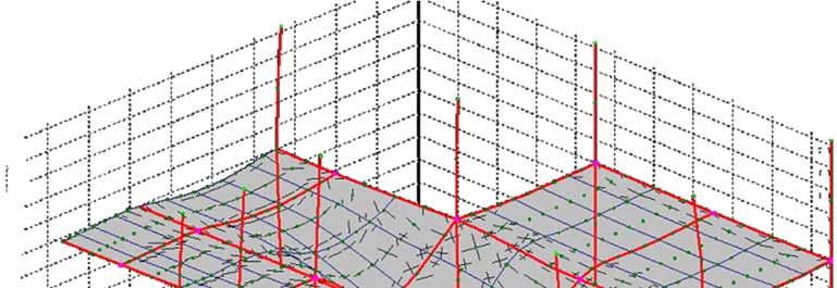
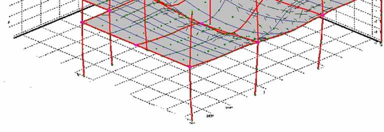
60 Floor structure around Column
61 Floor structure around Column 79 At ~500 C a 15m composite (secondary) beam has a free thermal expansion of ~90mm
62 Floor structure around Column 79 At ~500 C a 15m composite (secondary) beam has a free thermal expansion of ~90mm. If this is restrained by the noncomposite girder, it creates large transverse forces on the girder
63 Floor structure around Column 79 At ~500 C a 15m composite (secondary) beam has a free thermal expansion of ~90mm. If this is restrained by the noncomposite girder, it creates large transverse forces on the girder
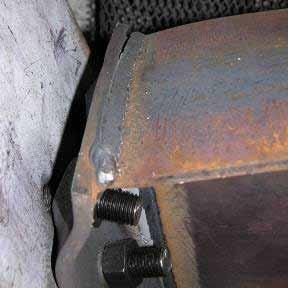
64 Girder to column connection at Column 79

65 Girder to column connection at Column 79 Resultant restraint force from secondary beams Shear forces on bolts
66 Floor structure around Column 79 At ~500 C a 15m composite (secondary) beam has a free thermal expansion of ~90mm. If this is restrained by the noncomposite girder, it creates large transverse forces on the girder. Bolts on seating plate and locating cleat fracture in shear (probably on Floor 13), and the girder collapses. This is repeated in sequence on lower floors due to impacts and similar restraint forces from simultaneous fires


67 67 The fall of WTC 7
68 Can we predict connection behaviour in fire??

69 Principal component zones of end plate Tension Column web Column flange End plate Column web Tension bolts Slip Beam web Beam web Column web Compression Beam flange, web Hogging Moment 69

70 The Component method with axial force Component model deals with load combinations automatically, though M f curves change due to thrust. K 1 K 2 K c 70

71 The Component method with axial force Component model deals with load combinations automatically, though M f curves change due to thrust. F 1 K 1 F t F 2 K 2 M F c K c 71

72 The Component method with axial force Component model deals with load combinations automatically, though M f curves change due to thrust. F 1 K 1 F t F 2 K 2 F F c K c 72
73 Component Based Connection Element (Block) Compression springs (column web) One set of tension springs per bolt row (T stubs, bolts) i j Zero length Shear spring (bolts) Beam end and centre line of column assumed to remain plane Tension and compression forces have different lines of action 73 Only depends on the geometry and the material of the connection
74 Component based connection element: beam shear panel 1 2 F w S f u 74
75 Component based connection element: beam shear panel 1 F f w u S 75
76 Component based connection element: beam shear panel 1 F f w u S
77 Component based connection element: including both shear panels F w f u S
78 Column element Component based connection element: centreline model including shear panels F w f u S Column Shear Panel element Connection element Beam Shear Panel element Beam element
79 Implementation of joint element in software L I K J
80 How do connections fail??
81 Beam section fracture in cooling Axial Force / steel strength Reduced restraint, higher ductility TENSION Stiff restraint Tensile failure of beam section Cooling COMPRESSION Beam temperature Heating Normalised axial force in restrained beam 81
82 Bolt row failures in heating Axial Force / steel strength TENSION COMPRESSION Tensile failure of beam section Bolt failure Bolt failure Bolt failure Bolt failure Beam temperature 82 Heating Normalised axial force in restrained beam
83 Bolt row failures in cooling Axial Force / steel strength Tensile failure of beam section Bolt failure Bolt failure Bolt failure Bolt failure Cooling TENSION COMPRESSION Beam temperature Heating Normalised axial force in restrained beam 83
84 How can we fully model progressive collapse?
85 Dynamic analysis to identify re stabilization P crit Load δ crit Unstable region Dynamic δ re-st Stable region Stable region Deflection 85
86 Where next? Temperature (ºC) J1 Rotation (rad) Rotation at J1 against temperature C Forces in Component (KN) Rotation (rad) Forces in bolt rows against rotation at J
 0.15 0.2 0.25 Rotation at J1 against temperature C1 0.")
 0 200 400 600 800 100 200 300 400 500 600 700 800")
87 Where next? Temperature (ºC) J1 Rotation (rad) Rotation at J1 against temperature C Displacement (mm) Temperature ( C) Displacement of top of column C1 against Temperature 1000
88 Problems 1. Building structure is optimised by designers and is therefore vulnerable to actions which have not been explicitly considered in design. 2. This can include local fractures and consequential progressive collapse of floors under impact and overload. Finally collapse of columns without support over multiple floors. Evidence of connection behaviour 1. Cardington shows connection phenomena which can happen. 2. WTC7 shows how design which is OK for normal temperatures can go disastrously wrong in fire. Predicting behaviour Thoughts 1. Fire resistant design based on isolated members simply is not adequate to predict connection fracture in complex structures. 2. The only feasible way for design seems to be global modelling with component based models.
89 Will the componentbased method work?
 25 20 15 10 5 0 0 20 40 60 Force 80")
90 Characterizing components for connection element Displacement (mm) Force
91 Tests on flush endplate connections 10 UC Grade 8.8 M20 bolts UB Connector View on A A t p α (Loading Angle) 91


92 Deformed Shape and Failure Mode At 20 o C 92
93 Comparison with web cleat tests : Loading at Component Model Test Force (kn) C 550 C 20 C 650 C Rotation (Degrees)
94 So where are we? Component models are: reliable in predicting component fracture, unreliable in predicting stiffness. Component based connection elements provide a practical way of modelling the progressive failure of connections through their components. When combined with static dynamic analysis they allow global structural analysis in fire scenarios which models progressive collapse of whole structures or large sub structures without excessive numbers of elements or computational effort. This could be used in performance based structural fire engineering design, to optimise the robustness of structures in fire.