THE JSCE DURABILITY DESIGN OF CONCRETE STRUCTURES AND A PROPOSAL FOR VIETNAM CONSTRUCTION INDUSTRY
|
|
|
- Matthew Morgan
- 5 years ago
- Views:
Transcription
1 THE JSCE DURABILITY DESIGN OF CONCRETE STRUCTURES AND A PROPOSAL FOR VIETNAM CONSTRUCTION INDUSTRY Koji SAKAI 1 SUMMARY Concrete is one of the most important materials employed in public works and building construction projects and a countless number of concrete structures have been constructed worldwide. Although concrete structures are designed on the basis of fundamental performance requirements, the background for design is drastically changing. This paper outlines sustainability issues, describes the present state of durability design, introduces durability design methods of the JSCE Standard Specifications for Concrete Structures, and discusses the future direction in the design of concrete structures. Keywords: Sustainable construction; durability design; JSCE Standard Specification; carbonation; chloride ions ingress; freezing and thawing action; chemical attack; alkali aggregate reaction; environmental design. INTRODUCTION Concrete is one of the most important materials employed in public works and building construction projects. It is estimated that more than a ton of concrete is produced each year for every human being on the planet. The estimated cement consumption of the world in 2002 and 2020 is 1696 and 2132 million tons, respectively 1). According to Humphreys et al. (Humphreys et al. 2002), cement consumption is expected to increase almost uniformly until the middle of this century, to reach 4 to 6 billion tons. These circumstances mean that energy consumption, resources depletion, CO 2 emissions, and other environmental impacts resulting from construction activities can no longer be ignored. The conventional design framework for concrete structures is primarily based on safety and currently focused on the aspects of durability. It is obvious that environmental aspects should be also incorporated into the design of concrete structures. From an environmental viewpoint, it can generally be thought that life-extension of a structure is directly related to the reduction of environmental impact. Therefore, the establishment of reasonable durability designs for concrete structures is very important. Although many efforts have been made to evaluate the durability of concrete structures, most of the existing design codes do not provide tools with the exception of the 1 Professor, Department of Safety Systems Construction Engineering, Kagawa University, JAPAN , sakai@eng.kagawa-u.ac.jp 1
2 JSCE Standard Specification for Concrete Structures (JSCE 2002). This paper outlines sustainability issues, describes the present state of durability design, introduces durability design methods of the JSCE Standard Specifications for Concrete Structures, and discusses the future direction in the design of concrete structures. Sustainable Development SUSTAINABILITY The true nature of global environmental problems is a result of economic society systems due to the explosion of industrialization since the Industrial Revolution, in which mass production, mass consumption and mass disposal have been pursued. Such systems have caused the destruction of ecological system due to the use of land, natural resource and energy depletion, and water pollution, the emission and diffusion of hazardous substances and greenhouse gases, waste excretions, etc. Mankind has realized that these impacts exceed its allowable limit. As a fundamental scheme in social economic activities, therefore, a paradigm shift to sustainable development has become significant. The concept of sustainable development was proposed in Brundtland Report (WECD 1987). Sustainable Development was defined as development which meets the needs of the present without compromising the ability of future generations to meet their own needs. The report described three fundamental aspects: environmental protection, economic growth and social equality. After the publication of this report, a keyword Sustainable Development became firmly established as the final target of mankind. For the sustainable development in the earth, fundamentally we have to prevent the global warming which is thought due to greenhouse gases, such as CO 2. The Kyoto Protocol adopted at the International Conference for the Prevention of Global Warming (COP3) in 1997 required Japan, the U.S.A. and the E.U. to reduce by their emission of greenhouse gas by 6, 7 and 8%, respectively, compared to 1990 levels. Sustainable Construction Recently, the companies manufacturing general industrial products have increased their concerns for environments. This is due to the fact that they have realized the limitation in their business in which the limit of resources is not considered. Civil engineering structures and buildings are largely different from general industrial products in the following points: (1) They are not mass productions. (2) They have long life span. (3) They have strong public aspects. It seems that due to these special features, the concept of environmental design in the life cycle scenario did not emerge. Construction is one of the biggest industries around world. Construction has major effects on 2
3 the global environment because construction is a major consumer of land and raw materials and the operation of building is the biggest energy consumer. The quality and quantity of construction will affect future generations. Therefore, construction industry has a significant role for sustainable development in which the needs of future generation have to be taken into consideration. In other words, sustainable construction has to be considered as a part of sustainable development. Sustainable construction will be achieved by taking the following factors into consideration: (1) environmentally friendly construction materials (2) energy efficiency in buildings (3) construction and demolition waste management Construction materials provide the environmental impacts at each stage of the life cycle, such as raw materials extraction, processing, manufacture, distribution, and construction works (on-site materials fabrication, use, and demolition waste). To reduce the environmental impacts, it may be the most important to minimize the amount of virgin materials use. Over-design and under-design should be avoided. The environmental design system of buildings and structures, in which the selection of materials and structural shape, construction works, maintenance, and demolition/ recycling are included, should be established to minimize the use of resources and energy and to manage construction and demolition waste. In the conceptual design, in which the owner and designer should agree, environmental aspects for sustainable construction have to be considered in addition to general matters, which include structural concept, location, cost, construction term, and performance requirements. Concrete is made of cement, water and aggregates. Cement production consumes lots of energy and emits a large amount of CO 2. In addition, aggregate extraction causes natural destruction which includes land use, loss of eco-system, amenity loss etc. The construction and demolish waste are one of the serious problems in construction industry. On the other hand, several industrial by-products, such as blast furnace slag, fly ash, silica fume etc., have been used in concrete. Thus, concrete has a great role for sustainable construction. In other words, sustainable concrete construction has to be considered. PRESENT STATE OF DURABILITY DESIGN We have been facing various and sometimes serious durability problems in concrete structures. According to ACI Cement and Concrete Terminology (ACI 116R ), durability is defined as the ability of concrete to resist weathering action, chemical attack, abrasion, and other conditions of service. The severity of environmental, chemical, and physical attacks on concrete depends on the properties of concrete and its exposure conditions. The general deterioration phenomena of concrete structures include alkali-aggregate reaction 3
4 (Photo 1), freezing and thawing (Photo 2), corrosion of reinforcement in concrete (Photo 3), carbonation of concrete, etc. The alkali-aggregate reaction can be prevented by several countermeasures such as the setting of threshold content of alkali in cement, the utilization of cementitious materials, etc. Freezing and thawing resistance can be secured by introducing an appropriate air-void system in concrete. Concerning the corrosion of reinforcement, it has been understood that concrete cover and its quality are the key and many efforts have been made to evaluate it quantitatively. The carbonation of concrete has a disadvantage in reinforced concrete because the ph of carbonated concrete drops to a value below the passivation threshold of steel. Nevertheless, most of the existing durability design codes do not provide a tool for evaluating the ingress of chloride ions in concrete, the carbonation of concrete due to carbon dioxide, and other deteriorations. Durability design may be categorized into three levels as follows: (1) prescriptive design (2) performance-type design (3) performance-based design In the prescriptive design for the durability of concrete, for example, the maximum water cement ratio and minimum cement content are provided depending on the exposure conditions. In the EN206 (BS EN ), the recommended limiting values for composition and properties of concrete are provided as indicated in Table-1. In the ACI Building Code Requirements for Structural Concrete (ACI ), total air content for frost-resistant concrete, requirements for special exposure conditions (Table-2), requirements for concrete exposed to deicing chemicals, and requirements for concrete exposed to sulfate-containing solutions (Table-3) are provided for durability. All requirements are stipulated in a prescriptive manner. It may be said that prescriptive design is based on the simplification of safety side from real performance. However, the background of most provisions is unclear. For example, the water cement ratio for corrosion protection of reinforcement in concrete cannot be easily determined because it is directly related to the concrete cover. Therefore, it is more reasonable and accurate to consider performance with time. In principle, the required performance should be verified through a direct analysis of time-dependent behavior of a concrete structure under the assumed environmental actions. At present, however, it is difficult to predict the durability performance of a structure throughout the lifespan because of the inadequacy of the models necessary for calculations. Further development of research on numerical approaches will pave the way to the realization of performance-based design. Under the current situations, what we can do in our codes is to introduce a performance-type design in which principal durability performance is considered with time. The JSCE Standard Specifications for Concrete Structures introduced such a design method for durability design for the first time in
5 Framework JSCE STANDARD SPECIFICATION FOR CONCRETE STRUCTURES The JSCE Standard Specification stipulates the following fundamental requirements at the design stage of structures: At the design stage, structural details such as the shape, size, reinforcement arrangement, required properties of concrete and reinforcing material, method of construction (in situ, pre-cast, etc.) and maintenance plan should be decided also taking into account the economic consideration. It should also be ensured that the required performances in terms of serviceability, safety, durability and compatibility with the environment, etc. are satisfied over the service life of the structure. The JSCE Standard Specifications for Concrete Structures consist of the following four versions: (1) Structural performance verification (2) Seismic performance verification (3) Materials and construction (4) Maintenance The procedure for verifying mechanical performance of concrete structures is given in the specification for structural performance verification and the specification for seismic performance verification. The performance of concrete structures varies over time due to environmental conditions and other factors. The examination on whether such change is in acceptable range is described in the specification for materials and construction. Once the construction is completed, it is difficult to repair, strengthen or renovate concrete structure, so thorough investigation at the beginning stage of design, accurate prediction for possible problem in service life and future maintenance are of great importance. The specification for maintenance provides basic knowledge for the maintenance of concrete structures. Figure 1 indicates the framework of the contents to be covered in each specification. Durability Verification of Concrete Structures General concept In the durability verification of concrete structures in the Specifications for Materials and Construction, the following provisions are provided: (1) The performance of concrete structures shall remain the required performance throughout its designed service life. (2) This chapter deals with the performance verification for the deterioration of structure on account of carbonation, the ingress of chloride ions, cyclic freezing and thawing action, chemical attack, and alkali aggregate reaction. The chapter also deals with the verifications of water tightness and fire resistance of the structure. It is further recommended that the simultaneous action of two or more mechanisms should be appropriately considered when 5
6 required. It should be noted that this provision requires the performance verification of durability for concrete structures, not for concrete. This means that even if concrete or reinforcements partially deteriorate, there will be no problems when utilized under a certain condition in which the required performance of the concrete structure is satisfied. This is a fundamental concept in the specification, which is completely different from the existing prescriptive durability design methods. Verification for carbonation The verification of a structure for carbonation is conducted as follows: (1) The required performance of concrete structures shall not be impaired by the carbonation of concrete. (2) Verification for carbonation should be conducted by ensuring that y d γ 1.0 (2.2.1) i y lim Where, γ I : Factor representing the importance of the structure. In general, it may be taken as 1.0, but may be increased to 1.1 for important structures. y lim : Critical carbonation depth of steel corrosion initiation. In general, it may be obtained from Equation (2.2.2). ylim = c c k (2.2.2) Where, c :Expected value of cover thickness (mm). In general, it may be taken as the design cover thickness (mm) c k : Remaining non-carbonated cover thickness (mm). This may be taken as 10mm for structures in a normal environment, and between 10 and 25 mm for structures located in chloride rich environments. y : Design value of carbonation depth. In general, it may be obtained from Equation (2.2.3). d Where, α :Design carbonation rate ( mm d y d = γ α t (2.2.3) k cb = α β γ, where e d c year ), which is given as α k : Characteristic value of carbonation rate ( mm year ) t : Designed service life of structure (year). Equation (2.2.3) should be used to evaluate the carbonation depth only for a structure whose service lives is less than 100 years. β e : Coefficient representing the extent of environmental action. It may be taken as 1.0 for environments in which structures are difficult to be dried out or for north-facing surfaces. It may be increased to 1.6 for environments in which structures can be easily dried out or for South-facing surfaces. Where, α : Design carbonation rate ( mm d = α β γ, where k e c year ), which is given as α k : Characteristic value of carbonation rate ( mm year ) t : Designed service life of structure (year). Equation (2.2.3) should be used to evaluate the carbonation depth only for structures whose service lives is less than 100 years. 6
7 β e :Coefficient representing the extent of environmental action. It may be taken as 1.0 for environments in which structures are difficult to be dried out or for north-facing surfaces. It may be increased to 1.6 for environments in which structures can be easily dried out or for South-facing surfaces. γ cb : Safety factor to account for the variation in the design value of carbonation depth. Normally it may be taken as In the case of high fluidity concrete, it may be taken as 1.1. γ c : Factor to account for the material properties of concrete. In general it may be taken as 1.0, but should be taken as 1.3 for upper portions of the structure. However, if there is no difference in the quality of concrete in structure and that of laboratory-cured specimens, the value of 1.0 may be adopted for the whole structure. (3) When normal Portland cement is used, water to cement ratio lower than 50%, and the thickness of cover concrete not smaller than 30cm, the verification for carbonation may be omitted. Figure 2 shows the relation between the effective binder ratio and coefficient of carbonation speed. The data consist of different types of binder, including fly ash and blast furnace slag. Although there is large scattering in the data, the following equation was introduced: α k = W/B where W/B: water binder ratio It is obvious that the carbonation of concrete is dependent on the exposure environment of the structure. To consider the effect of exposure environment, environmental factorβ e was introduced. As indicated in Fig. 3, theβ e -values for concrete in a dry environment or when concrete faces south and that in a wet environment or when the concrete faces north are 1.6 and 1.0, respectively. Fig. 4 shows the minimum cover at different water cement ratios and service years in which the corrosion of reinforcing bars due to carbonation of concrete is prevented. Verification for reinforcement corrosion due to the ingress of chloride ions The verification of a structure for reinforcement corrosion due to the ingress of chloride ions is conducted as follows: (1) The required performance of concrete structures shall not be impaired by corrosion of the reinforcement caused by the ingress of chloride ions. (2) The verification for reinforcement corrosion caused by the ingress of chloride ions should be conducted by ensuring that C d γ i 1.0 (2.3.1) Clim Where, γ i : Factor representing the importance of the structure. In general, it may be taken as 1.0, but should be increased to 1.1 for important structures C lim : Critical chloride concentration for initiation of steel corrosion. It may be normally taken as 1.2 kg/m 3. However in cases when freezing and thawing action is likely to occur simultaneously, the critical value should be suitably reduced. C :Design value of chloride ion concentration at the depth of reinforcement. It may be d 7
8 obtained from Equation (2.3.2). (1 O. Pc Cd = γ cl C0 erf ( )) (2.3.2) Q D t C 0 :Assumed chloride ion concentration at concrete surface (kg/m 3 ). Generally, it may be obtained from Table c : Expected value of concrete cover thickness (mm). In general, the designed cover thickness may be selected. t : Designed service life of the structure (year). It may be noted that Equation should be used to evaluate the concentration of chloride ions at the location of the reinforcement only in cases the service life is less than 100 years. γ : Safety factor, to account for the variation in the Design value of the chloride ion cl concentration at the depth of reinforcement Cd. Normally, it may be set at 1.3, but in the case of high fluidity concrete, a value of 1.1 may be selected. D d : Design value of diffusion coefficient of chloride ions into concrete (cm 2 /year) It may be obtained from Equation w w Dd =ƒá c Dk + D0 l w (2.2.3) a γ c : Factor to account for the material properties of concrete. In general, it may be set at 1.0 but should be taken as 1.3 for upper portions of the structure. However, if there is no difference in the quality of concrete in structure and that of specimens cured in laboratory, this value may be taken as 1.0 even for all portions of the structure. D k :Diffusion coefficient of chloride ion in concrete (cm 2 /year) D 0 : Constant to express the influence of crack on the movement of chloride ions into concrete (cm 2 /year). In general, it may be taken as 200cm 2 /year w: Crack width (mm)as per Section of the Standard Specifications for Concrete Structures (Volume I - Design). w a : Allowable crack width (mm), as per Section of the Standard Specifications for Concrete Structures (Volume I - Design). w/l: Ratio of crack width to crack interval as per Section of the Standard Specifications for Concrete Structures (Volume I - Design) 2 s erf(s) is error function, defined as erf s = e 2 η ( ) dη 1/ 2 ƒî 0 d 2 Table Chloride ion concentration at concrete surface C 0 (kg/m 3 ) Distance from the coastline (km) Tidal and splash zone Near coastline Considering the effect of elevation above the water surface, an increase of 1m in elevation may be considered to be equivalent to a horizontal distance of 25m. The equivalent C 0 may then be calculated from the above table. (3) When it is difficult to meet the stipulation in (2) above, other steps to ensure the required durability should be considered. Appropriate countermeasures, such as coating concrete surface with appropriate coating materials, using corrosion resistant reinforcing materials and adopting cathodic protection are recommended under these conditions. In such cases, the 8
9 method to be used should be properly evaluated, taking into account the maintenance plan of the structure. (4) In cases when ingress of chloride ions from the environment is not likely, the reinforcement may be regarded to be protected from chloride-induced corrosion, provided the concentration of chloride ions in fresh concrete does not exceed 0.30 kg/m3. In the case of using prestressing steel material, which is likely to be more susceptible to stress-corrosion, the limit should be suitably reduced. (5) In cases when deicing agents are used, the durability performance of concrete structures should be especially considered. Further, ingress of chloride ions into concrete should be prevented using water proofing or providing adequate drainage. In the calculation, a chloride diffusion coefficient must be set as the design value. This means that the actual concrete has a diffusion coefficient for which the designed value is on the safety side. In the specification, the following equation for the prediction of the diffusion coefficient of actual concrete, D p, were introduced as the predicted values: (a) When ordinary Portland cement is used log D p = -3.9 (W/B) (W/B) 2.5 (b) When blast furnace slag and/or silica fume are used log D p = (W/B) (W/B) 2.2 These equations were introduced on the basis of a large amount of data shown in Fig. 5. Large data scattering is also seen in the chloride diffusion coefficients. The reason the JSCE decided to introduce such provisions is very simple. It is essential for us to pursue a direction for evaluating the durability performance of concrete structures. A prototype provision will accelerate research work focused on improving the equations. More extensive work is necessary. Verification for cyclic freezing and thawing action The verification of a structure for cyclic freezing and thawing action is conducted as follows: (1) The required performance of concrete structure shall not be impaired by cyclic freezing and thawing action. (2) Verification for freezing and thawing action should be conducted by ensuring that Emin γi 1.0 (2.4.1) E d where, γ i is a factor representing the importance of the structure. In general, it may be taken as 1.0, but may be increased to 1.1 for important structures. E :Design value of relative dynamic modulus of elasticity. d k = Ek γ c E : Characteristic value of the relative dynamic modulus of elasticity. γ c :Material factor. In general, it may be set at 1.0, but should be taken as 1.3 for upper positions of the structure. However, if there is no difference in the quality of concrete in the structure (in situ) and that of laboratory-cured specimens, this value may be set at 1.0 for all positions. E min : Critical minimum value of relative dynamic modulus of elasticity to ensure required performance of the structure under cyclic freezing and thawing action. In general, it may be obtained from Table Table Minimum critical level, E min (%), of relative dynamic modulus of elasticity to 9
10 ensure a satisfactory performance of the structure under cyclic freezing and thawing action Climate Section Severe weather conditions or frequent cyclic freezing and thawing action Not so severe weather conditions, atmospheric temperature rarely drop to below 0 C Exposure Thin 2) General Thin 2) General of structure (1) Immersed in water or often saturated with water 1) (2) Not covered in item (1) above and subjected to normal exposure conditions ) Structures close to the water surface or in contact with water such as waterways, water-tanks, abutments of bridge, bridge piers, retaining walls, tunnel linings, etc. Besides, structures such as slabs, beams etc not close to the water surface but may be exposed to snow, water flow, spray, etc., also belong to this category. 2) Members with thickness less than 20cm may be considered thin. 3) Generally, the verification in section (2) may be omitted in cases when the characteristic value of relative dynamic modulus of elasticity, E k, is higher than 90. Verification for chemical attack The verification of a structure for chemical attack is conducted as follows: (1) The required performance of concrete structure shall not be impaired by chemical attack (2) In case the concrete meets the criteria for resistance against chemical attack, the structure may be assumed that its performance will not be impaired on account of chemical attack (3) In cases when the action of chemical attack is very severe, measures, such as covering the surface of concrete and using corrosion resistant reinforcement, to control the chemical attack should be taken. The effectiveness of such measures should be evaluated using appropriate methods, taking into account the maintenance plan of the structure. Due to the limited understanding on how the deterioration of concrete under chemical attack results in the degradation of the structure performance, unfortunately, quantitative evaluation has not been realized. Therefore, only conceptual provisions are introduced for the verification of a structure for chemical attack. In an actual verification, accelerated, exposure tests, or any other suitable tests shall be performed on concrete specimens at the conditions as close to the actual conditions as possible. When it is required that the deterioration of concrete is just within the level that does not affect the required performance of the structure, instead of the verification on the resistance to chemical attack of concrete, it is allowed in the specification to use the following maximum water-cement ratio: (a) When concrete are in contact with soil or water, which contain 0.2% or more of a sulfate such as SO 4, maximum water cement ratio is 50%. (b) When deicing salts are used, maximum water cement ratio is 45%. Verification for alkali-aggregate reaction 10
11 The verification of a structure for alkali-aggregate reaction is conducted as follows: (1) The required performance of concrete structure shall not be impaired by alkali aggregate reaction (2) In case the concrete meets criteria for resistance against alkali aggregate reaction, the structure may be assumed that its performance will not be impaired on account of alkali aggregate reaction. (3) The performance of the concrete structure against alkali aggregate reaction may be secured using appropriate surface treatment. In such cases, the effectiveness of the treatment shall be evaluated using appropriate methods, taking into account the maintenance plan of the structure. The most reliable method to verify the resistance of a structure to alkali aggregate reaction is to cast concrete specimens in the same conditions to the real structure, expose them in similar environmental conditions and confirm the possibility of crack formation. However, considering various involving factors, such as the testing time as well as the required expense, the need to test concrete at various kinds of materials and proportions, etc., this real exposure test is not always feasible. Therefore, at present the verification for the resistance to alkali aggregate reaction is usually carried out on the basis of the accelerated tests using concrete specimens. The JCI AAR-3 [Test method for evaluation of aggregate reactivity in concrete] is one of such methods that may be used as a reference in carrying out accelerated tests. It has been confirmed from laboratory experiments and field investigations that an expansion level of less than 0.1% at the age of 6 months in the test carried out based on this method, may not cause appreciable degradation in the performance of concrete structures. This level can thus, be used as a standard to decide whether or not the expansion on account of alkali aggregate reaction could be detrimental. Namely, the verification for resistance to alkali aggregate shall be conducted out by insuring that: γ p L L p max 1.0 Where, L p :Estimated expansion of concrete due to alkali aggregate reaction (%). Generally, this is set equal to the expansion at 6-month exposure in the test in accordance with JCI AAR-3 (Determination of alkali silica reactivity in concrete). L max :Maximum permissible expansion rate at which concrete still satisfies the required resistance against alkali aggregate reaction. Generally, it may be set at 0.10%. γ : Safety factor to account for the accuracy in determining. Generally it is set in p between 1.0 and 1.3. When tests are carried out in accordance with JCI AAR-3, it may be taken to be 1.0 When using aggregates conforming to classification A (non-reactive) as per the test method for evaluation of aggregate reactivity in concrete and restraining alkali aggregate reaction in concrete using appropriate cement, the verification for the resistance to alkali aggregate reaction can be omitted. 11
12 PARADIGM SHIFT OF DESIGN FOR CONCRETE STRUCTURES According to the Gaia hypothesis (Joseph 1993) by meteorologist James E. Lovelock and microbiologist Lynn Margulis, the earth s climate and atmospheric environment are controlled by animals, plants and microorganisms living on the earth. There is no doubt that the earth has an extremely rare environment in the overwhelmingly vast universe. Its entire equilibrium is thought to be maintained by direct and indirect mutual dependence of various creatures from bacteria to humans. While the atmosphere of the earth in its early days was almost entirely composed of carbon dioxide in the same way as Venus and Mars, it currently consists of 78% nitrogen, 21% oxygen and 0.03% carbon dioxide. It means that this condition has maintained the environment necessary for the survival of life. Human activities, however, began to affect this. It is said that the ancestors of mankind emerged 5 million years ago, and more than 6 billion people currently live on the earth. Such a large number of people consume enormous amounts of resources and energy to secure their living environment, and these amounts are increasing with accelerating speed. This fact is a threat to the Gaia control of the global environment. Disorder of the regulating function of the global environment directly and indirectly affects human health, primary production, biodiversity and social assets. Although the range of environmental issues, which are considered to be the greatest challenge of the 21st century, is wide, measures and actions based on advanced ideas must be taken steadily and responsibly to solve those problems. The field of construction is also no exception. Current design methods concerning concrete structures have been organized with the focus on safety. Although durability has recently been incorporated in the JSCE Standard Specification as a function of time, it must be said that the environmental viewpoint, which is an essential element of the life-extension of structure and resource efficiency, was extremely weak. In safety design, the safety of a structure is verified from the relationship between the cross-sectional force determined by the load and structural type, and the design sectional bearing force of an actual member section. In durability design, the durability is verified from the relationship between the performance evaluation index calculated based on a prescribed life cycle and the limit value. The design service life of a structure is determined by considering the service life required of the structure, the maintenance/management method, environmental conditions and the durability and economic efficiency required of the structure. The act of promoting reduction in the environmental impact in design of a concrete structure, taking global warming and resource efficiency into account, can be considered basically the same as safety and durability design. We have two options. One is not to regulate the reduction of environmental impacts until a serious situation occurs. The other is to introduce a social and economic system including a mechanism for the reduction of environmental 12
13 impacts. In other words, no matter what the main factor is, to set the limit value, a system that enforces consideration of greenhouse gas emission reduction in design should be introduced. The same can be said of other environmental aspects. If regulation values exist, they can be used as limit values. Thus, a design method of concrete structures, in which three required performances structural (safety, serviceability), durability and environmental performance are satisfied at the same time, will be introduced in the future. We may call it Environmental Design, which is completely different from conventional design systems in the point that the environment is incorporated into design, a paradigm shift of design for concrete structures At the fib Commission 3, where the author serves as chairman, basic examination of environmental design has been conducted (fib 2004). Development of Guidelines for environmental design is currently under way. The Task Group on Environmental Aspect, the Specification Subcommittee, the Concrete Committee of the Japan Society of Civil Engineers, where the author serves as convener, also collected and sorted information on environmental aspects and published Recommendation on environmental performance verification for concrete structures (Draft) (JSCE 2005). The Subcommittee on the evaluation of the environmental impact of concrete, the Concrete Committee of the Japan Society of Civil Engineers also presented useful information (JSCE 2004). The author believes that we can achieve global-scale accountability for environmental problems in the field of concrete if we can disseminate environmental design in the near future through these activities, establish an integrated design system to cover structure, durability and environment comprehensively. A movement towards a paradigm shift of design for concrete structures is accelerated A PROPOSAL FOR VIETNAM CONSTRUCTION INDUSTRY Vietnam is expected to pursue further advancements by increasingly developing its infrastructure. In other words, the development of infrastructure is most significant for the future of Vietnam. To date, advanced countries have vastly built up their infrastructures; experiencing many problems in the meanwhile. One such problem is the deterioration of concrete structures. In one extreme case, this deterioration resulted in a bridge collapse. At the present stage, it is considered that many concrete structures have potential risks in terms of their durability. This leads to another problem, which is, the percentage of construction budgets dedicated to repair, strengthening and renewal projects is steadily increasing. In Japan, the construction investment dropped by approximately 40 percent in the past 10 years and a further decline is expected. Such developments in the construction industry will result in the potential loss of construction technology and know-how, which have been accumulated over a long period of time. If there are no new projects, valuable technology will disappear. In a global sense, it will lead to the deterioration of resource and energy efficiency, since developing countries would be unable to utilize the technology accumulated by advanced countries and would be required to build up know-how on the construction 13
14 technology on their own. Therefore, developing countries would probably repeat the same failure that advanced countries have experienced. Developing countries are required to establish an infrastructure development strategy based on the assumption that the technology accumulated by advanced countries can be efficiently utilized. Considering that these regions, in which 80 percent of the world s population lives, are pursuing further economic development, it is very significant for them to learn from the experiences of advanced countries and reduce global environmental impacts. There is no need to hesitate in introducing highly advanced technology from advanced countries. In fact, Vietnam does not always have to start from the ground up. In terms of global environmental issues, it is important for Vietnam to be able to use the best available technologies and work to further develop these technologies in manner that is most suitable for Vietnam. The introduction of advanced technology as a project to utilize the Kyoto Protocol CDM is an option. Thus, the concept of infrastructure development in developing countries largely differs from the conventional infrastructure development. The idea of sustainable construction will have much more significance in developing countries than in advanced countries. With this background in mind, matters that the Vietnam construction industry should take into consideration in the future can be summarized as in following proposals: (1)Formulation of an appropriate infrastructure development plan with consideration paid to reducing environmental impacts. (2)Proactive introduction of advanced construction technology. (3)Consideration of Kyoto Protocol CDM projects. (4)Promotion of research and development of construction technology. (5)Development of a quality assessment tests for construction materials. (6)Development of design standard specifications for structure and durability. (7)Education of construction workers. (8)Introduction of an asset management system. (9)Creation of an international network for researchers and engineers. CONCLUDING REMARKS There is no need to mention that concrete structures have contributed to the social and economic activities of human beings. On the other hand, civil engineering and building structures consume enormous resources and emit huge amount of greenhouse gases. Therefore, there is no question about the extreme importance of introducing effective systems to reduce the environmental impact in the field of construction. Durability problems of concrete structures are directly linked to environmental impacts because the shortening of the lifespan will result in the wasteful utilization of limited natural resources. Thus, it will become more and more important to modify the framework of design of concrete structures 14
15 by incorporating environmental aspects into the current design systems and to improve durability design methods. We are now in the turning point in the history of concrete engineering. It is believed that there are quite a few things that the industry, academia and government of Japan can contribute to the development of Vietnam s infrastructure. We hope that this joint seminar will trigger the promotion of the national land development of Vietnam through cooperation between our two countries with a focus on global environmental issues. REFERENCES Ken Humphreys and Maha Mahasenan, Toward a Sustainable Cement Industry, Climate Change Substudy 8, World Business Council for Sustainable Development, 2002 Japan Society of Civil Engineering, Standard specifications for concrete structures-2002, materials and construction, The World Commission on Environment and Development (WECD), Our Common Future, Oxford U.P., ACI Committee 116, Cement and Concrete Terminology, ACI 116R-00, British Standard EN206-1, Concrete - Part 1: Specification, performance, production and conformity, American Concrete Institute, Building Code Requirements for Structural Concrete (ACI318-02) and Commentary, L. E. Joseph (Translated to Japanese by Y. Takahashi), GAIA, TBS Brittanica, fib, Environmental Design, Bulletin 28, Japan Society of Civil Engineers, Recommendation on Environmental Performance Verification for Concrete Structures (Draft), Concrete Library 125, Japan Society of Civil Engineers, Environmental impact evaluation of concrete (Ⅱ), Concrete Engineering Series 62,
16 Table 1 Recommended limiting values for composition and properties of concrete EN206 Maximum w/c Minimum strength class Minimum cement content (kg/m 3 ) Minimum air content (%) Other requirements No risk of corrosi on or attack X0 C12/15 C20/25 - Carbonation-induced corrosion Exposure classes Chloride-induced corrosion Sea water Chloride other than sea water Freeze/thaw attack Aggressive chemical environments XC1 XC2 XC3 XC4 XS1 XS2 XS3 XD1 XD2 XD3 XF1 XF2 XF3 XF4 XA1 XA2 XA C25/30 C30/37 C30/37 C30/37 C35/45 C35/45 C30/37 C30/37 C35/45 C30/37 C25/30 C30/37 C30/37 C30/37 C30/37 C35/ ) 4.0 1) 4.0 1) Freeze/thraw resisting aggregates in accordance with the recommendations in pren 12620:1996 Surfateresisting cement 2) 1) Where the concrete is not air entrained, the performance of concrete should be tested according to ISO FFF-1 in comparison with a concrete for which freeze/thaw resistance for the relevant exposure class is proven. 2) When SO 4 1eads to exposure classes XA2 and XA3, it is essential to use sulfate-resisting cement. Where cement is classified with respect to sulfate resistance, moderate or high sulfate-resisting cement should be used in exposure class XA2 (and in exposure class XA1 when applicable) and high sulfate-resisting cement should be used exposure class XA3. 16
17 Table 2 Requirements for special exposure conditions [ACI ] Exposure condition Maximum water-cementitious materials ratio, by weight, normalweight aggregate concrete Minimum f c, normalweight and lightweight aggregate concrete, psi Concrete intended to have low permeability when exposed to water Concrete exposed to freezing and thawing in a moist condition or to deicing chemicals For corrosion protection of reinforcement in concrete exposed to chlorides from deicing chemicals, salt, salt water, brackish water, seawater, or spray from these sources TABLE 3-Requirements for concrete exposed to sulfate-containing solutions [ ACI318-02] Sulfate exposure Negligible Moderate Severe Water soluble sulfate (SO 4 ) in soil, percent by weight Sulfate (SO 4 ) in water, ppm Cement type Maximum watercementitious materials ratio, by weight, normalweight aggregate concrete Minimum f c, normalweighty and lightweight aggregate concrete, psi 0.00 SO 4 < SO 4 < SO 4 < SO 4 <1500 II,IP(MS), IS(MS), P(MS), I(PM)(MS), I(SM)(MS) SO 4 < SO 4 <10,000 V Very severe SO 4 >2.00 SO 4 >10,000 V plus pozzolan
18 Required performance of structure Construction condition Design of structure Design Earthquake resistance design volume Maintenance management manual Setup of structure Setup of concrete Construction Construction Plan Setup of maintenance management Selection of reinforcing material Setup of construction Verification of structural perfoamance Structural perfoamance Durability perfoamance Figure 1 Works at design stage Coefficient of carbonation speed (cm/ year) Fly ash committee OPC Rapid PC Low heat PC Fly ash C Blast furnace C α= W/B Coefficient of carbonation speed (cm/ year) East West South North Southeast Northeast α=β( W/B ) β= 1 β= Effective water binder ratio (%) Figure 2 Relation between water binder ratio and carbonation speed Effective water binder ratio (%) Figure 3 Relation between environment and carbonation speed 18
19 Ordinary portland cement 7 6 Blast furnace cement (Slag content 40%) Years 100 Concrete cover (cm) Wet environment, βe=1.0 Dry environment, βe=1.6 Years Concrete cover (cm) Wet environment, βe=1.0 Dry environment, βe= Water cement ratio Water cement ratio Figure 4 Minimum cover at different water cement ratio and service years Diffusion coefficient, Dp (cm 2 /year) E+02 1.E+01 1.E+00 1.E-01 Water cement ratio (W/C) Ordinary Portland cement concrete log Dp=-3.9(W/C) (W/C)-2.5 Diffusion coefficient, Dp (cm 2 /year) E+01 1.E+00 1.E-01 Water binder ratio (W/C) Concrete using blast furnace slag and/or silica fume log Dp=-3.0(W/C) (W/C) E-02 1.E-02 Figure 5 Diffusion coefficient 19


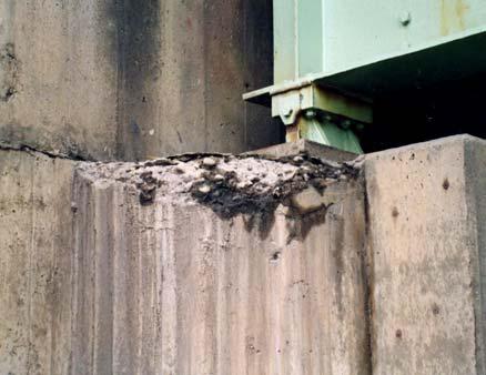


20 Photo 1 Damage due to alkali-aggregate Photo 2 Frost damage Photo 3 Corrosion of reinforcing bars 20