Construction of a One-Third Scale Model of the National Aerospace Plane-NASP*
|
|
|
- Jody Martin
- 5 years ago
- Views:
Transcription
1 Int. J. Engng Ed. Vol. 13, No. 2, p. 153±159, X/91 $ Printed in Great Britain. # 1997 TEMPUS Publications. Construction of a One-Third Scale Model of the National Aerospace Plane-NASP* K. R. HALL, S. W. BROWN, A. G. BENNETT and M. RAIS-ROHANI Raspet Flight Research Laboratory, Department of Aerospace Engineering, Mississippi State University, MS 39762, USA The senior design class in Aerospace Engineering at Mississippi State University and the facilities at Mississippi Sate University and the facilities at Raspet Flight Research Laboratory were chosen for the construction of a one-third scale model of the National Aerospace Plane (the NASP). This choice was based upon the use of the senior design class for planning, management, and construction of the model and upon the use of a five-axes gantry robot router for construction of the molds for making the composite components. The construction technique chosen was the conventional frame-stringer-skin method used in aircraft construction and the material chosen was fiberglass. The use of AUTOCAD for converting data from external NASP drawings into working frame stations provided student experience in the use of CAD, and the conversion of sheets of construction foam into frame molds, stringer molds, skin molds, and molds for other pieces of the model by use of the gantry robot provided student experience in the use of CAM. This paper will provide an overview of the entire construction process with emphasis upon the use of the gantry robot in the construction. The pictorial history of the model construction culminating in the rollout ceremony will be furnished. INTRODUCTION THIS is the story of a very successful learning experience for a group of aerospace engineering students at Mississippi State University. During the fall semester of 1991, the NASP Joint Program Office and the Virginia Space Consortium conducted a nationwide competition open to all four-year colleges and universities with engineering programs. The winner of the competition was to construct a one-third scale model of the conceptual NASP airplane for demonstration at various air shows. The proposal from Mississippi State University was selected for its student involvement, university support, and the rapid composite prototyping capabilities available at Raspet Flight Research Laboratory. The model was to be designed and built at the Raspet Flight Laboratory (RFRL) and was to be an all composite one-third scale model based upon the conceptual drawings of the NASP aircraft. The project was to be completed in one semester, and the rollout ceremony for the-finished NASP model was scheduled for June 10, The design The NASP Joint Program Office required the use of fiberglass-reinforced composites as the primary material for the NASP model. This meant that each part of the model structure would require an appropriate mold and overall accuracy would have to be maintained to an exacting tolerance for the parts * Accepted 5 May 1997 Copyright AIAA, reprinted with permission to mesh. A frame/stringer/skin design was chosen to educate the students in modern aircraft construction, and to provide the structural rigidity required by the NASP Project Office. The model was required to have removable wings, vertical tails, and landing gear. It was to be trailerable, to be statically displayed on its landing gear, to be movable on the landing gear, and to be pedestal mounted with the landing gear removed. The model was to weigh approximately 5000 pounds. The design considerations for the structure were based upon the model weight and the requirements that it must withstand a 100 mph cross wind, the loads imposed by a man walking anywhere on the fuselage, and the impact loads due to golfball sized hailstone impacts. The frame/ stringer construction provided a skeleton frame with sufficient rigidity and the skin was designed to withstand the impact loadings. The skin was constructed as a triple layer sandwich construction of fiberglass sheet/foam sheet/fiberglass sheet which provided resilience and structural integrity. The landing gear was determined to be best represented by a tricycle arrangement with four wheel trucks for each of the main gear and a dual wheel nose gear. The foam core in the skin was replaced with an aluminum core at the attachment points for the gear. The people Forty undergraduate students, three faculty members, several RFRL technicians, people from the Virginia Space Consortium, and people from the NASP Joint Program Office comprised the team who conspired to construct the NASP model. The students were divided into eight 153


2 154 K. R. Hall et al. Fig. 3. Artist's concept. Fig. 1. Preliminary meeting. groups: a fuselage group, a robot group, a jigging group, a wings group, a vertical tails group, and `odds and ends' group, a landing gear group, and a project tracking group. Each group was assigned a faculty advisor and a lab technician and the groups were fluid as some people worked in more than one group. The separate groups pursued parallel construction paths which was necessary for meeting the project completion deadline. It should be emphasized at this point that the students did the design and construction work. The faculty members and consultants were advisors. Figure 1 shows an initial meeting with representatives of the faculty, the students, the Virginia Space Consortium, and the NASP Joint Program Office. Figure 2 shows some additional consultation in the RFRL hangar area where the project was to be constructed. The problem At the initiation of this project, there was no definitive NASP configuration to use in the construction of the model. Artist's conceptual models and a three-view external shape AUTOCAD drawing were all the available information for the team (Fig. 3). Since the model structure was not even similar to the proposed NASP structure, the problem was to design a structure with the external shape of the AUTOCAD drawings. The tools RFRL regularly uses AUTOCAD for design of aircraft components. The technicians are familiar with fiberglass wet layup processes and many of the students work part-time at RFRL while attending the university. This gave some credibility to the capability of the team to construct the fifty feet long, one-third scale fiberglass NASP model. One additional item made the project feasible in the specified time. RFRL had recently acquired a five-axes gantry-mounted robot router. The router was capable of movement within a four feet by six feet by eighteen inches volume and could pitch away from the vertical axis and rotate about the vertical axis for a conical motion about the vertical axis. This versatile tool with its five axes of motion was a solution looking for a problem. The NASP model construction was that problem. With the computer controlled robot router, complex female mold shapes were easily cut into sheets of standard construction foam. Figure 4 shows the router at work cutting out the NASP model canopy from a foam block. The computer control of the router produces accuracy and repeatability in the molds cut out and also provides a means of frame alignment by drilling holes into the frames at specified points. When the frames were mounted in the wooden jigs, a surveyor's transit was used to align the holes in the frames to provide horizontal accuracy. With a hole in each side of each frame, the frames were aligned with no twist to the structure. Each frame was constructed from fiberglass cloth and resin laid into the mold generated by the router. Figures 5 and 6 show some of the students putting cloth and resin into molds. To keep the cloth in the mold and to squeeze some of the resin Fig. 2. Consultants. Fig. 4. Robot router.


3 Construction of a One-Third Scale Model of the National Aerospace Plane-NASP 155 Fig. 5. Student wet layup (A). Fig. 9. Frame/stringer/skin. Fig. 6. Student wet layup (B). Fig. 10. Test section. Fig. 7. Frame mold. Fig. 11. Four front frames. Fig. 8. Skin panel. Fig. 12. Students trim frames.


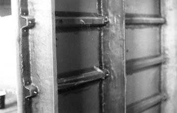
4 156 K. R. Hall et al. Fig. 13. Front frames on jig. Fig. 16. Left forward view. Fig. 14. Transit leveling structure. Fig. 17. The fuselage group. The results were comforting in that there was more strength than expected. From the test section construction, the frame spacing for the NASP model was chosen, and the thickness of the sandwich skin was chosen. The strength of the hatshaped stringers verified that they were a good choice for the model. CONSTRUCTION Fig. 15. Internal forward view. out, a plastic bag was placed over each mold with fiberglass and resin and the air vacuumed out of the plastic bag. This used the atmospheric pressure to press the cloth into the mold and to squeeze the resin uniformly into the cloth. Figures 7 and 8 show a frame mold being vacuum bagged and a skin panel being vacuum bagged. To test the accuracy of the process and to check on the strength of the proposed frame/stringer/skin combination, a test section of three frames, several stringers and the proposed skin was constructed. Figures 9 and 10 show the test section and show details of the construction. Figure 9 shows a closeup view of the frame/stringer/skin construction and Fig. 10 shows the completed test section. With verification provided by the test section, construction of the NASP model went into full speed. Since the NASP fuselage does not have a uniform cross-section, various frames with the appropriate front-to-back taper were constructed from molds produced by the router. Figure 11 shows four successive frame stations laid flat in their approximate locations in the fuselage. Frames were also constructed for the wings and vertical tails as shown in Fig. 12. Construction proceeded in parallel for the various components of the model. Figure 13 shows several frames attached to a fuselage jig and Fig. 14 shows students using the transit to produce a level unwarped structure. Figure 15 shows more frames attached with longitudinal stringers attached. Figure 16 shows a side view of the fuselage structure emphasizing the stringer attachment. Figure 17 shows the fuselage construction crew with most of the frames and stringers in place. Figure 18 is another view of


5 Construction of a One-Third Scale Model of the National Aerospace Plane-NASP 157 Fig. 18. Skeleton with nosecap. Fig. 21. Mechanical skin fasteners. Fig. 19. Vacuum bagged skin panel. Fig. 22. Rear view at 40 days to rollout. Fig. 20. Applying skin to skeleton. the skeleton structure with the foam nose cap in place. The structure is beginning to assume a sleek aerodynamic look. With the frames and stringers in place, the skin needs to be attached. Figure 19 shows another view of the vacuum bag process applied to the skin sandwich to produce the three-layer skin. Figures 20 and 21 show the skin being mounted upon the skeleton structure. It is necessary to use mechanical fasteners to hold the skin in the curved shape next to the frame/stringer skeleton while the assembly bonds into a unit. These fasteners are removed after the bonding. Note, in the backgrounds of Figs 21, 22 and 23, the announcement of the number of days until rollout is schedules. In Figure 21, `40 Days to Fig. 23. Most of skin applied. Rollout' and the skin is just being applied. In Figure 22, `40 Days to Rollout' and rear is not done. In Figure 23, `33 Days to Rollout' and most of the skin has been applied and the endless job of sanding is underway. The skin must be glass smooth before paint is applied or every imperfection will be apparent. Figure 24 shows the results later with the skin sanded smooth and with the canopy and nose cap blocks attached to the fuselage. Figure 25 shows the dual wheel nosegear attached to the model. Figure 26 shows one of the four wheel truck main landing gear and its attachment to the right side fuselage. The model is now complete except for the finishing touches. Figure 27 is an example of sand, fill, sand, fill,


6 158 K. R. Hall et al. Fig. 24. Canopy and nose applied. Fig. 27. Final sanding and filling. Fig. 25. Twin wheel nose gear. Fig. 28. Base coat of paint applied. Fig. 26. Quad wheel main gear. Fig. 29. The 1 3 scale NASP model. sand, etc. Figure 28 is the model with its base coat of white paint applied (Note `6 Days To Rollout') and Fig. 29 is the finished product with wings and vertical fins attached pulled out onto the taxi strip for the RFRL. This is obviously a publicity photo, so in Fig. 30, a representative group of students, faculty, technicians, staff, and friends appear with the finished one-third scale NASP model. CONCLUSION The construction of the one-third scale NASP model was a very satisfying project. Everyone involved was able to see a product completed Fig. 30. The NASP model and friends.
7 Construction of a One-Third Scale Model of the National Aerospace Plane-NASP 159 and delivered on schedule. The RFRL group has proven their ability in rapid prototyping of composite aircraft components. The robot router has proven its worth in providing molds which produced the finished product in a record time of 105 days from project beginning to rollout. The technicians at RFRL have built another composite aircraft structure. The students involved have acquired an immense knowledge of project planning, project management, aircraft design and structural analysis, and hands-on experience in composite aircraft construction. Mississippi State University can indicate with pride the finished product was completed at RFRL. The NASP Joint Program Office actually got a better model then they were expecting due to the use of conventional aircraft construction techniques and the product was delivered when promised.