Fire Test Report. Test Number 1243 Dated 22 September Prepared for:
|
|
|
- Noah Armstrong
- 5 years ago
- Views:
Transcription

1 SPECIALIST VENTILATION SERVICES Ltd Unit 11A, Greencroft Industrial Park Annfield Plain, Stanley, County Durham, DH9 7YB Tel: Fax: Fire Test Report Fire resistance test on a Tri-pro 315 Dia & 100 Dia single blade combination fire, smoke and volume control damper mounted in a 1 hour rated 100mm thick metal framed stud partition wall. Test Number 1243 Dated 22 September Prepared for: Tri-Air Innovations Ltd Windgates, Church Lane, Waltham, Canterbury, Kent, CT4 5SS. Fire Test Carried out independently by: Lorient Polyproducts Ltd Heathfield Industrial Estate, Newton Abbot, Devon, TQ12 6UD. Report written and prepared by: Andy McArthur of Specialist Ventilation Services Ltd. 1
2 Contents: Reference Page 1) Summary 3 2) Objective 4 3) Test Construction 4 4) Test Procedure 5 5) Results and observations 6 6) Test criteria 7 7) Conclusions 7 8) Specimen drawings 8 9) Photographs 10 10) Time Temperature Curve 24 11) Furnace Calibration Certificate 25 2
3 1) Summary Two Tri-Pro Single blade Combination Fire / Smoke & Volume control circular steel damper with dimensions of 315 dia and 100 dia were built into a 100mm thick metal stud partition wall with a double skin plasterboard each side designed to achieve a minimum fire resistance of 1 hour. The entire assembly was submitted to an ad-hoc fire resistance test adopting the appropriate procedures and criteria of BS 476 time temperature curve for over 90min. The dampers were tested with the operating mechanism and installation plate on the unexposed side of the test specimen and in this orientation satisfied the adopted criteria as follows: Integrity: 90min. After which the external face of the wall showed signs of cracking and was not considered to maintain its integrity. The damper remained in its installed position with the blade firmly closed. 3
4 2) Objective The test was undertaken at the request of Tri-Air Innovations Ltd to determine the performance of their Tri-Pro Combination fire / smoke and volume control damper when submitted to an ad-hoc fire resistance test adopting the procedures and criteria of BS 476 Part 22 when installed in a recognised 1 hour fire rated Stud partition wall for integrity of the damper and installation method. 3) Test Construction The dampers were a Tri-Pro steel fire, smoke and volume control damper size 315 & 100dia installed into corresponding apertures in the specimen wall as detailed below and secured using plasterboard steel screws and steel washers through the fixing slots in the installation plate through the plasterboard and into the metal studs of the wall. Care was taken not to over tighten these screws so expansion could occur. Construction of the damper and materials are as described in the product literature and as tested by BRE report number FG7386 (January 2002) for 4 hours. A 1000 x 1000 x 100mm thick, metal frame stud partition wall constructed using a 50mm metal stud with a double skin of 12.5mm (25mm total) plasterboard on both sides. Each layer of plasterboard was secured to the metal studding framework using industry standard steel plasterboard screws. The plasterboard was sealed with intumescent mastic around the perimeter of the furnace to ensure integrity of the specimen. The test construction is further detailed in photographs FTP 1 to FTP 4 and prior to the start of the test in FTP 5 & 6 4
5 4) Test Procedure The test was carried out on the 22 nd September 2010 and was witnessed by a representative of Tri-Air Innovations Ltd and Lorient Polyproducts Ltd. The dampers were tested with the operating mechanism i.e. fusible cartridge and handle external to the face of the wall / furnace. The dampers were set in the open position secured by the fusible cartridge. See FTP 6 After 20 seconds the 100dia damper closed and after 40 seconds the 315dia damper closed. The delay from one to the other was due to the different heights of installation of the dampers and the time taken for the temperature in the furnace to rise above 72 C in relation to the installation height. Furnace Control: The furnace temperature was measured using three thermocouples positioned symmetrically inside the furnace approximately 100 mm back from the face of the specimen wall. The furnace was controlled so that the mean temperature readings of the three thermocouples followed the time temperature curve specified in accordance with BS 476 Part 20. The actual furnace time temperature curve has been plotted against the standard time temperature curve for comparison. See section 10). Temperature measurements of damper blade: Periodic external surface temperatures of the damper blade were taken for reference using a hand held laser thermometer at 2 meters from the furnace. 5
6 5) Results and Observations The following observations are of the damper and wall specimen when viewed from the external side of the furnace unless noted as internal. The internal views were observed through a 100 x 100 observation window at the rear of the furnace. The internal dimensions of the furnace are approximately 1200 x 1200 x 1200mm, allowing a test specimen of 1000 x 1000mm Observations: Time Min s Sec s 0 20 s 40 s 5 min min Observations Test Started. 100dia damper 75 C 315dia damper 75 C Moisture staining on front of plasterboard above 315 unit Small amount of steam / smoke around installation plate of 315 unit (18Pa) Plasterboard starts to crack on internal side of wall 1 st layer. (18Pa) 797 C 812 C no appreciable change in appearance. 850 C (18-20pa) no appreciable change in appearance. No appreciable change in appearance. 888 C no appreciable change in appearance. Staining on LHS and above 315 damper. Damper blade 880 C on single skin 820 C on double skin. 315 unit. Damper blade 883 C on single skin 830 C on double skin. 315 unit. 2 nd Layer of internal plasterboard starts to crack. 947 C Internal first layer of plasterboard has broken apart & fallen away. Installation plate of 315 unit starts to bow in the middle with the heat on the LHS by about 6mm at the highest point. Damper blade 988 C on single skin 941 C on double skin. The blade of 315 unit starting to glow. 2 nd Layer of internal plasterboard comes away exposing the metal frame. Signs of scorching around 315dia unit of external plasterboard. External surface of wall starts to glow around 315 and 100 dia unit Heavy glow on wall around both dampers. Damper blade temperature 997 C. No change to damper other than the bow in the installation plate of 315 unit has increased to 8mm on the LHS. The damper is still secured in position however the plasterboard is showing signs of fine cracks appearing in external surface of the wall. No appreciable change in damper appearance. Cracks are spreading a little in the plasterboard. Furnace temperature 1025 C. External surface of wall showing signs failure with wide spread scorch marks and cracks getting larger. Test Stopped. 6
7 6) Test Criteria The criteria for failure under integrity for un-insulated door-sets and shutter assemblies are given below. In the absence of an ad-hoc specific standard test for dampers the same criteria (BS 476 part 20/22) were used. a) When collapse or sustained flaming for not less than 10 seconds on the unexposed face of the furnace occurs. b) When a 6mm dia gap gauge can penetrate through a gap into the furnace and be moved in the gap for a distance of at least 150mm. c) When 25mm dia gap gauge can penetrate through a gap into the furnace. The results only relate to the behavior of the specimen(s) and wall construction during the test. They do not reflect the actual behavior in fires. 7) Conclusions The Tri-Pro circular steel combination fire, smoke and volume control damper mounted in an industry considered 1 hour Stud partition wall comprising of a double skin plasterboard 12.5mm (x2) each side of a 50mm metal stud as described in this report was submitted to an ad-hoc fire resistance test adopting the appropriate procedures and criteria of BS 476 Part 22 for a duration of 90 minutes. The damper tested with the mechanism on the external face of the furnace and as such satisfied the adopted criteria as follows. Integrity 90 minutes No through gap developed during the test which exceeded the limits for failure of integrity. No sustained or even partial flaming was evident at any time during the test. This report covers a test which was conducted to a procedure which is not the subject of any British Standard specification but the test utilises the general principles of the fire resistance testing given in BS 476 Parts
8 8) Specimen drawings Front Elevation of As Installed specimen wall c/w Tri-Pro Combination Dampers Furnace exterior 100 Dia unit. Damper Blade Damper Blade. Specimen Stud partition wall 50mm Metal Frame behind double skin plasterboard 315 Dia unit. VENTILATION SERVICES Ltd Tri-Pro Combination Damper. Fire Test. Stud Partition Wall (AS INSTALLED) Tri-Air Innovations Ltd. 28th Sept 2010 NE
9 Specimen Drawings continued Sectional part drawing of As Installed specimen wall c/w Tri-Pro Combination Damper. Tri-Pro Combination Damper. Fire Test, AS INSTALLED arrangement for 1 hour "Stud Partition" installation WITHOUT independent suspension of the damper other than the screw fixings through the slots of the installation plate. Intumescent Mastic applied to the back of the Installation Plate 25 50mm 25 Mineral Wool insulation material. Closed Nominal Duct Dia. 100 dia & 315 dia. Intumescent Mastic Fix through slots provided in Installation Plate using approved or assed fixings. DO NOT over tighten. Double Skin Plasterboard. (2 off 12.5mm) NOTE: 50mm Metal frame stud. This view top & bottom is illustrative only, the test has vertical studs only without any horizontal noggins or braces. VENTILATION SERVICES Ltd Tri-Pro Combination Damper. Fire Test. Stud Partition Wall (AS INSTALLED) Tri-Air Innovations Ltd. 28th Sept 2010 NE

10 9) Photographs Wall Construction: FTP 1 FTP 2 10


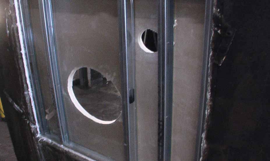
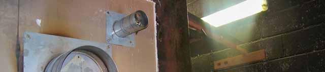
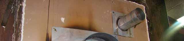
11 FTP 3 Wall with double skin inside and one outside prior to the last external skin. FTP 4 External face of specimen wall with Tri-Pro Dampers fitted. 11


12 FTP 5 Inside Face of wall prior to fitting to furnace. FTP 6 Internal face showing dampers open prior to starting the test. 12


13 FTP 7 Internal view of furnace with front removed. FTP 8 Fire test record showing test number and time clock 13


14 FTP 9 Fire test after 10 min s showing dampers closed. FTP 10 Fire test after 20 min s 14


15 FTP 11 After 25 min s showing damper blade condition with furnace at 812 C FTP 12 Internal view of plasterboard cracking at min s 15


16 FTP13 Fire test after 30 min s FTP 14 Fire test after 40 min s 16


17 FTP15 Fire test after 45 min s showing 100 dia damper close up. FTP16 Fire test after 50 min s showing 315 dia damper at 883 C 17


18 FTP 17 After 55 min s the internal second layer of plasterboard starts to crack FTP18 After 60 min s the wall and damper are still demonstrating integrity. 18


19 FTP19 After 70 min the internal plasterboard has collapsed exposing the vertical studs. FTP 20 Scorching is apparent on the external front plasterboard. 19


20 20


21 FTP 22 After 80 min s more intense scorching is apparent and the damper blades start to glow. FTP 23 21


22 FTP 24 After 85 min s the front of the wall shows sever burn marks and starts to glow. FTP 25 The 315 dia damper can be seen to glow and the frame bows to about 8mm at the middle on the top and both sides due to the destruction of three levels of plasterboard. 22


23 FTP 26 After 90 min s 1-2 mm wide cracks appear on the outer layer of plasterboard above the 315 dia damper. FTP 27 with the time now over 100 min s and the internal temperature of the furnace at 1025 C the wall can be seen to fail in places. 23


24 FTP 28, 29 & 30 The test is now complete and the front of the furnace removed, showing a clear view of the internal surface of the specimen wall and dampers. 24
25 10) Time Temperature Curve A B C D 01/01/ /01/ /02/ /03/ /04/ /05/ /06/ /07/ /08/ /09/ /10/ /11/ /12/ /01/ /02/ /03/ /04/ /05/ /06/ /07/ /08/1901 A, B & C are the measured temperatures of the thermocouples inside the furnace and D is the Time Temperature Curve as specified by BS 476 Due to the time records being every 10 seconds it is not possible to show the time line along the bottom of the graph above in text hence the unusual display. This is however available in table format if required. The temperature is recorded in the vertical axis of the graph. 25

26 11) Furnace Calibration Certificate REPORT ENDS. 26
27 Comments & Notes: Report prepared by Andy McArthur. Signed: 27