SIGMA MAYTRX OLLDE ENGLISH GETTING STARTED GUIDE RETAINING WALL
|
|
|
- Jessie McDowell
- 5 years ago
- Views:
Transcription


1 SIGMA MAYTRX OLLDE ENGLISH GETTING STARTED GUIDE RETAINING WALL
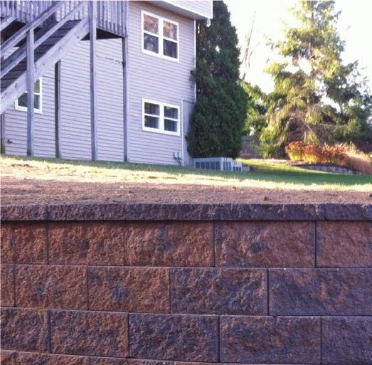
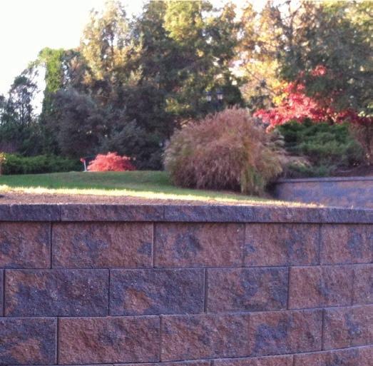
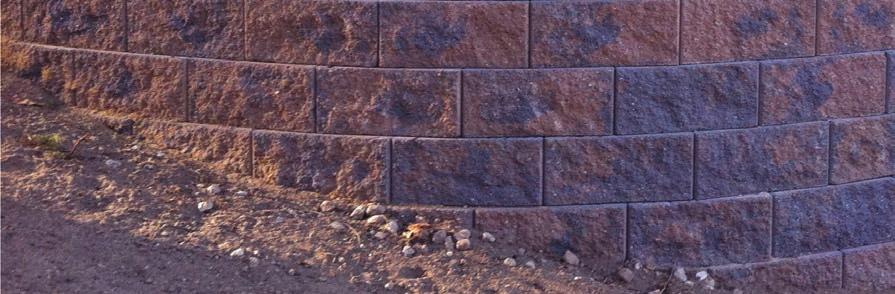
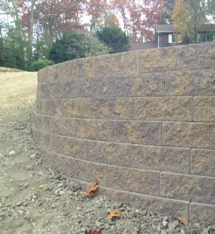
2 SIGMA-MAYTRX OLDE ENGLISH PROJECTS Cambridge Wall Book 135

3 BUILDING A WALL SIGMA-MAYTRX OLDE ENGLISH This is a starting guide to the Cambridge Retaining Wall Systems including Maytrx, Sigma and Olde English Walls. In this book we cover the general points that are important in building a retaining wall. For any wall over 36 you should also consult our Sigma or Maytrx Pro-Guide that is available to download or view at cambridgewallsupport.com or cambridgepavers.com. This will guide you through the factors that influence the strength of the finished wall including load, slope, soil condition, water runoff, geogrid layers, etc. Many municipalities require all retaining walls over a certain height to have a stamp made by a state approved engineer or similar professional that will specify how your wall is built. You will find information on the Cambridge program that allows you to get a free wall design or to receive low cost stamped specifications in your state on page 28 of this book. The Sigma stone face and accessories are similar in texture and color to the Cambridge Maytrx line of wall and Outdoor Living Kits. So if you require a tall wall in the rear of your property as well as a double sided wall in your garden and maybe in the future a fire pit or an outdoor fireplace, the finishes will all match. Cap Stone Clean Stone Sigma, Maytrx or Olde English Wall Geogrid Toe Compacted Fill Perforated Pipe Foundation Retaining Walls are made up of more than the Wall Stones. Any wall over 36 consists of the pieces in the illustration above. Foundation, drain pipe, drainage stone, geogrid reinforcement, Wall Stones, Cambridge Cap Stones and select fill are all engineered and installed depending on the site conditions. View Page XX of this book for further information. 136 Cambridge Wall Book


4 SIGMA-MAYTRX OLDE ENGLISH FOUNDATION Protection of soils A proper moisture content is required to achieve proper compaction. Foundation soils and all fill soils should be protected from rain and freezing during construction. Frozen soils must NOT be used in retaining wall construction. compactor Compact sub base Compact the soils under the leveling pad to 95% Standard Proctor Density or greater. If organic soils are encountered they must be removed and replaced with acceptable soils. trench width +/- 3 feet TIP:This may, be the proper time to install the drain pipe see the drain pipe guidelines on page XX) Base stabilization The purpose of the leveling pad is to provide a level surface to place the first course of units on. More importantly, the leveling pad spreads out the load of the retaining wall units over a larger area. The strength and quality of your retaining wall depends greatly on the strength and quality of your leveling pad materials. Over time the sub-base material can migrate into the leveling pad, thus contaminating it and diminishing its structural integrity. Base stabilization fabric (SRW SS5) separates the leveling pad materials from the sub-base materials so that its strength will not be compromised. stabilization fabric Sigma 6 wall has 4 knobs, install for 6 degree setback, or break off front knobs for near vertical (right) Maytrx Walls come in 6 or 3 height may be used as single sided (Retaining Wall or double sided Freestanding Wall Olde English Wall may be setback 3/8 to build a wall that can be combined with engineering to serve as a retaining wall Cambridge Wall Book 137
. Compact leveling pad to 95% Standard Proctor Density or greater.")

 Screed the leveling pad material smooth, being careful that the screed pipes stay level and at the correct elevation.")
5 FOUNDATION SIGMA-MAYTRX OLDE ENGLISH Leveling pad If possible, start the leveling pad at the lowest elevation of the wall. It is easier to step up than to step down. Place well graded gravel or drainage aggregate in the leveling pad trench (see Excavation section for minimum leveling pad depths). Compact leveling pad to 95% Standard Proctor Density or greater. compactor drainage aggregate Screeding the leveling pad Place screed pipes across the compacted leveling pad (see illustration). If a 10 foot screed is used, an 8-9 foot separation of screed pipes works well on straight walls. Screed pipes may need to be closer on curves or corners. Make sure the top of the screed pipes are at the correct bottom of the proposed block elevation and are level. Place the finish leveling pad material. (If more than 1 ½ is required, do the compaction again.) Screed the leveling pad material smooth, being careful that the screed pipes stay level and at the correct elevation. Repeat the screeding operation for the length of the leveling pad or if the wall steps up, to the 1st step of the leveling pad. Do not walk on or otherwise disturb the leveling pad prior to laying the first course of retaining wall units. screed pipes screed board levels 138 Cambridge Wall Book

 (see curve and corner guidelines beginning on page 14).")

6 SIGMA FIRST COURSE string convex curve concave curve PVC pipe Laying first course: SIGMA Use steel stakes and a string line to lay out straight sections of the retaining wall. String lines should be placed so that they go along the BACK of the block in order to ensure a straight line. As opposed to the rock face surface on many retaining wall units. If the string line is placed at the correct elevation it can be used to check elevation and side to side levelness of the retaining wall unit. For laying out a retaining wall that curves, flexible 3/4 PVC pipe works well (see illustration for staking) (see curve and corner guidelines beginning on page 14). It is very important that the 1st course of block is laid correctly because it will determine the alignment of the rest of the retaining wall. Any deviations will be magnified as the height of the wall increases. It is usually best to start at the lowest elevation of the retaining wall. Again, it is easier to step up than to step down. If the bottom of the retaining wall unit has lugs, lips, or any other protrusions, use a hammer and chisel to break them off. Carefully place the unit on the screeded leveling pad, using the string line (for straight walls) or the flexible PVC pipe (for curved walls) as alignment guides. NEVER let the unit touch the string, because if each unit touches the string it will gradually push it out of alignment, which will result in a crooked wall. A good distance from the string is 1/16-1/8 inch away. For outside or convex curves, if the retaining wall unit has wings at the back of the unit they may be broken off to facilitate tighter curves. Always check the level of the retaining wall units, front to back, side to side, and the elevation in relation to the adjacent units. string 2 level 4 level Cambridge Wall Book 139

 (see curve and corner guidelines beginning on page 14).")

 or the flexible PVC pipe (for curved walls) as alignment guides.")
7 INDEX MAYTRX Laying first course: Maytrx Use steel stakes and a string line to lay out straight sections of the retaining wall. String lines should be placed so that they go along the BACK of the block in order to ensure a straight line. As opposed to the rock face surface on many retaining wall units. If the string line is placed at the correct elevation it can be used to check elevation and side to side levelness of the retaining wall unit. For laying out a retaining wall that curves, flexible 3/4 PVC pipe works well (see illustration for staking) (see curve and corner guidelines beginning on page 14). It is very important that the 1st course of block is laid correctly because it will determine the alignment of the rest of the retaining wall. Any deviations will be magnified as the height of the wall increases. It is usually best to start at the lowest elevation of the retaining wall. Again, it is easier to step up than to step down. If the bottom of the retaining wall unit has lugs, lips, or any other protrusions, use a hammer and chisel to break them off. Carefully place the unit on the screeded leveling pad, using the string line (for straight walls) or the flexible PVC pipe (for curved walls) as alignment guides. NEVER let the unit touch the string, because if each unit touches the string it will gradually push it out of alignment, which will result in a crooked wall. A good distance from the string is 1/16-1/8 inch away. For outside or convex curves, if the retaining wall unit has wings at the back of the unit they may be broken off to facilitate tighter curves. Always check the level of the retaining wall units, front to back, side to side, and the elevation in relation to the adjacent units. string convex curve concave curve PVC pipe 140 Cambridge Wall Book

 (see curve and corner guidelines beginning on page 14).")

 or the flexible PVC pipe (for curved walls) as alignment guides.")
8 OLDE ENGLISH INDEX string convex curve concave curve PVC pipe laying first course: Olde English Use steel stakes and a string line to lay out straight sections of the retaining wall. String lines should be placed so that they go along the BACK of the block in order to ensure a straight line. As opposed to the rock face surface on many retaining wall units. If the string line is placed at the correct elevation it can be used to check elevation and side to side levelness of the retaining wall unit. For laying out a retaining wall that curves, flexible 3/4 PVC pipe works well (see illustration for staking) (see curve and corner guidelines beginning on page 14). It is very important that the 1st course of block is laid correctly because it will determine the alignment of the rest of the retaining wall. Any deviations will be magnified as the height of the wall increases. It is usually best to start at the lowest elevation of the retaining wall. Again, it is easier to step up than to step down. If the bottom of the retaining wall unit has lugs, lips, or any other protrusions, use a hammer and chisel to break them off. Carefully place the unit on the screeded leveling pad, using the string line (for straight walls) or the flexible PVC pipe (for curved walls) as alignment guides. NEVER let the unit touch the string, because if each unit touches the string it will gradually push it out of alignment, which will result in a crooked wall. A good distance from the string is 1/16-1/8 inch away. For outside or convex curves, if the retaining wall unit has wings at the back of the unit they may be broken off to facilitate tighter curves. Always check the level of the retaining wall units, front to back, side to side, and the elevation in relation to the adjacent units. Cambridge Wall Book 141

. Compact the backfill to 95% Standard Proctor Density or better. Keep heavy compaction equipment at least 3 feet away from the retaining wall units.")

 Drainage aggregate doesn t take as much force to compact correctly as the")
9 BACKFILL & COMPACTING SIGMA Backfill and compacting Always backfill and compact in 6-8 lifts, as each course of block is installed. Do NOT stack two or more courses and backfill in deeper lifts because it will be difficult, if not impossible, to achieve proper compaction. Place the backfill, leaving a minimum of 12 inches of space between the retaining wall unit and the backfill, for the drainage aggregate (1/2 to 3/4 angular gravel with a maximum of 5% fines). Compact the backfill to 95% Standard Proctor Density or better. Keep heavy compaction equipment at least 3 feet away from the retaining wall units. Lighter, walk-behind compaction equipment can be within the three foot area. Compact soil nearest the retaining wall units first, then work toward the back of the excavation. Clean out the 12 inch space behind the retaining wall unit with a shovel. Place the drainage aggregate behind and in between the retaining wall units and compact. (This sequence minimizes the tendency of units to tip forward during the compaction process) Drainage aggregate doesn t take as much force to compact correctly as the backfill material. If the retaining wall units have cores or openings, fill them with the drainage aggregate. Any backfill placed at the bottom (front) of the retaining wall should be compacted. backfi ll drainage aggregate 142 Cambridge Wall Book

.")

.")
10 SIGMA ELEVATION CHANGES & ADDITIONAL COURSES 1st unit of 2nd course top of unit elevation compact around last unit Elevation changes (stepping) The top of the first course unit will be the elevation of the leveling pad. Add 1/8-1/4 inch extra, to allow for a little settlement. Make sure the soil is compacted in and around the last couple of units in the first course. Prepare the stepped up leveling pad as previously instructed for base leveling pad. Place the first unit of the stepped up course upon the last and second to last unit of the first course (straddling in a half bond fashion). Place the second unit of the step up on the last unit of the first course, 1/2 on that unit and 1/2 on the stepped up leveling pad.»if geogrid is NOT going to be used, continue on to Additional Courses below.»if geogrid IS going to be used, skip to page 13 for installation guidelines before continuing on to additional courses. Additional courses Retaining wall units are connected by knobs, which align the units, provide unit to unit shear connection, and provide the automatic setback (otherwise known as batter). Sweep any drainage aggregate or soil off the top of the retaining wall units. Place the upper unit by straddling the 2 units below in a half bond fashion. Slide the unit forward, towards the face of the wall, engaging the connection device. Continue to install each course of retaining wall units, backfill and compact, place drainage aggregate, and core fill to the top of wall elevation. drainage aggregate Cambridge Wall Book 143


11 BACKFILL & COMPACTING OLDE ENGLISH Backfill and compacting Always backfill and compact in 6-8 lifts, as each course of block is installed. Do NOT stack two or more courses and backfill in deeper lifts because it will be difficult, if not impossible, to achieve proper compaction. Place the backfill, leaving a minimum of 12 inches of space between the retaining wall unit and the backfill, for the drainage aggregate (1/2 to 3/4 angular gravel with a maximum of 5% fines). Compact the backfill to 95% Standard Proctor Density or better. Keep heavy compaction equipment at least 3 feet away from the retaining wall units. Lighter, walk-behind compaction equipment can be within the three foot area. Compact soil nearest the retaining wall units first, then work toward the back of the excavation. Clean out the 12 inch space behind the retaining wall unit with a shovel. Place the drainage aggregate behind and in between the retaining wall units and compact. (This sequence minimizes the tendency of units to tip forward during the compaction process) Drainage aggregate doesn t take as much force to compact correctly as the backfill material. If the retaining wall units have cores or openings, fill them with the drainage aggregate. Any backfill placed at the bottom (front) of the retaining wall should be compacted. 144 Cambridge Wall Book

.")


12 OLDE ENGLISH ELEVATION CHANGES & ADDITIONAL COURSES Elevation changes (stepping) The top of the first course unit will be the elevation of the leveling pad. Add 1/8-1/4 inch extra, to allow for a little settlement. Make sure the soil is compacted in and around the last couple of units in the first course. Prepare the stepped up leveling pad as previously instructed for base leveling pad. Place the first unit of the stepped up course upon the last and second to last unit of the first course (straddling in a half bond fashion). Place the second unit of the step up on the last unit of the first course, 1/2 on that unit and 1/2 on the stepped up leveling pad.»if geogrid is NOT going to be used, continue on to Additional Courses below.»if geogrid IS going to be used, skip to page 13 for installation guidelines before continuing on to additional courses. Additional courses Retaining wall units are connected by knobs, which align the units, provide unit to unit shear connection, and provide the automatic setback (otherwise known as batter). Sweep any drainage aggregate or soil off the top of the retaining wall units. Place the upper unit by straddling the 2 units below in a half bond fashion. Slide the unit forward, towards the face of the wall, engaging the connection device. Continue to install each course of retaining wall units, backfill and compact, place drainage aggregate, and core fill to the top of wall elevation. Cambridge Wall Book 145


13 BACKFILL & COMPACTING MAYTRX Backfill and compacting Always backfill and compact in 6-8 lifts, as each course of block is installed. Do NOT stack two or more courses and backfill in deeper lifts because it will be difficult, if not impossible, to achieve proper compaction. Place the backfill, leaving a minimum of 12 inches of space between the retaining wall unit and the backfill, for the drainage aggregate (1/2 to 3/4 angular gravel with a maximum of 5% fines). Compact the backfill to 95% Standard Proctor Density or better. Keep heavy compaction equipment at least 3 feet away from the retaining wall units. Lighter, walk-behind compaction equipment can be within the three foot area. Compact soil nearest the retaining wall units first, then work toward the back of the excavation. Clean out the 12 inch space behind the retaining wall unit with a shovel. Place the drainage aggregate behind and in between the retaining wall units and compact. (This sequence minimizes the tendency of units to tip forward during the compaction process) Drainage aggregate doesn t take as much force to compact correctly as the backfill material. If the retaining wall units have cores or openings, fill them with the drainage aggregate. Any backfill placed at the bottom (front) of the retaining wall should be compacted. 146 Cambridge Wall Book

.")


14 MAYTRX ELEVATION CHANGES & ADDITIONAL COURSES Elevation changes (stepping) The top of the first course unit will be the elevation of the leveling pad. Add 1/8-1/4 inch extra, to allow for a little settlement. Make sure the soil is compacted in and around the last couple of units in the first course. Prepare the stepped up leveling pad as previously instructed for base leveling pad. Place the first unit of the stepped up course upon the last and second to last unit of the first course (straddling in a half bond fashion). Place the second unit of the step up on the last unit of the first course, 1/2 on that unit and 1/2 on the stepped up leveling pad.»if geogrid is NOT going to be used, continue on to Additional Courses below.»if geogrid IS going to be used, skip to page 13 for installation guidelines before continuing on to additional courses. Additional courses Retaining wall units are connected by knobs, which align the units, provide unit to unit shear connection, and provide the automatic setback (otherwise known as batter). Sweep any drainage aggregate or soil off the top of the retaining wall units. Place the upper unit by straddling the 2 units below in a half bond fashion. Slide the unit forward, towards the face of the wall, engaging the connection device. Continue to install each course of retaining wall units, backfill and compact, place drainage aggregate, and core fill to the top of wall elevation. Cambridge Wall Book 147


15 INSTALLATION SIGMA-MAYTRX OLDE ENGLISH Capping Clean the top of the retaining wall units of all rock, dirt, and dust. Place a bead of retaining wall adhesive around the top of the last retaining wall unit. Place the cap on the retaining wall units. Note: A string line can be used to help line up the caps and straighten any waves that may have developed in the retaining wall. If a special cap unit is not used, bond the top course to the course just below. Applies to all the Wall Systems, 13 Caps and Large Caps are used on Maytrx and Sigma, Olde English uses the stone turned to make a cap cap adhesive Bring the fabric under the Cap filter fabric Place filter fabric on top of the backfill, over the drainage aggregate, and up against the top units or caps before placing the top/planting soils. It is recommended that the top/planting soils should be an 8 inch layer of impermeable soils. The filter fabric will help prohibit the migration of the fines from the planting soil down into the drainage aggregate and out the face of the retaining wall, thus preventing the plugging of the drainage aggregate and staining of the wall face. swale to divert water final steps of building the wall When finishing the project make sure that the final grade, both the top and bottom of the wall, are shaped so as to divert any water runoff away from the retaining wall. Protect the planting soil from erosion during heavy rains. 148 Cambridge Wall Book


16 SIGMA-MAYTRX OLDE ENGLISH INSTALLATION» Geogrid All installation instructions are the same as for gravity retaining walls EXCEPT for the addition of geogrid. Geogrid reinforces the soil, thus allowing taller walls to be constructed. Bi-directional/bi-axial geogrids, means the geogrid is the same strength in both directions. Because of that, this geogrid can be either rolled out parallel to the retaining wall or perpendicular to the retaining wall. If the geogrid depths are the same as the roll width, it may be more efficient to roll out the geogrid parallel to the retaining wall. If the geogrid depths called for are different than the roll width or if the wall curves, it is best to roll out the geogrid perpendicular to the retaining wall. (Not all geogrids are bi-axial, stronger geogrids must be rolled out perpendicular to the retaining wall.) stakes geogrid geogrid Using geogrid Geogrid depth is measured from the face of the retaining wall unit, to the back of the reinforced soil. Geogrid coverage should be 100%. However, the edges of the geogrid, should NEVER overlap. (See page 14 for curve and corner geogrid installation procedures.) Use your design table(s), found in page 26 of this guide to determine which course(s) of block to install the geogrid on and how deep it extends into the reinforced soil. Place the geogrid as far forward on the retaining wall unit as possible without it showing through the front/face of the retaining wall. Make sure that any connecting devices are engaged by the geogrid. Lay the geogrid flat from the wall units to the tail of the geogrid. The backfill, drainage aggregate, and core fill should be level with the top of the retaining wall unit and the geogrid should be as smooth as possible, with no pockets that would create voids under the geogrid. Place the next course of block on top of the geogrid and fill the cores with drainage aggregate, if applicable. Pull the geogrid taught, being careful not to pull the units back away from the connecting device or disturb the alignment of the units. Use landscape staples or stakes to hold the geogrid in place. geogrid elevations set to engineer design Cambridge Wall Book 149


17 INSTALLATION SIGMA-MAYTRX OLDE ENGLISH Using geogrid (continued) Do not drive or compact directly on the geogrid. A minimum of 6 inches of soil is recommended to cushion the geogrid. When backfilling over the geogrid, work the soil from near the retaining wall units toward the tail of the geogrid. When compacting over the geogrid, work from near the retaining wall units toward the tail of the geogrid. This procedure helps keep the geogrid taught. See the curve and corner instructions starting below, for geogrid placement. continue building wall Continue building the retaining wall by returning to additional courses on page 11. Convex Outside Curves To achieve desired curve alignment, use 3/4 flexible PVC pipe to outline the back of your retaining wall unit location. This will give you a guideline to help achieve smooth and accurate curves. If possible, it is best to start building a curve from the center of the curve and work outward in both directions. Start at the same location for all additional courses of retaining wall units. If the unit has wings at the back of the block, one or both may be broken off to achieve a tighter radius. Because of the batter (unit setback), the bottom course radius will be larger than the radius of the top course. The taller the wall the larger the bottom course radius needs to be in relation to the top course radius. Convex curve geogrid placement Geogrid coverage should be 100% butted together, but NOT overlapped on the retaining wall units. The geogrid tail, starting just behind the unit will be overlapped. A minimum of 3 inches of soil must be placed between these overlapping geogrid layers. work left PVC pipe smaller radius start center center of curve larger radius work right no overlap 3 backfi ll materials 150 Cambridge Wall Book


 the bottom course radius will be smaller than the radius of the top course.")


18 SIGMA-MAYTRX OLDE ENGLISH INSTALLATION PVC pipe center of curve Concave inside curves To achieve desired curve alignment, use 3/4 flexible PVC pipe to outline the back of your retaining wall unit location. This will give you a guideline to help achieve smooth and accurate curves. If possible, it is best to start building a curve from the center of the curve and work outward in both directions. Start at the same location for all additional courses of units. Because of the batter (unit setback) the bottom course radius will be smaller than the radius of the top course. The taller the wall the smaller the bottom course radius will be in relation to the top course radius. small radius large radius work left start center work right no overlap Concave curve geogrid placement Geogrid coverage should be 100% butted together, but NOT overlapped on the retaining wall units. There will be a V or pie shaped wedge of soil starting just behind the units which will not be reinforced. To compensate for the unreinforced section, on the next course of retaining wall units, geogrid is placed by centering over the pie shaped wedge of unreinforced soil below. center to reinforce triangle zone Cambridge Wall Book 151
19 INSTALLATION SIGMA Outside 90 corner Lay the corner according to the retaining wall system instructions. Some systems will have special corner units, some will have hand splitting lines, and others will require cutting. Each course is usually laid opposite of the course below. Where connecting devices cannot be used on corner blocks be sure to keep the same batter (setback) as the rest of the retaining wall. Outside corners should be bonded with retaining wall adhesive where connecting devices are unable to be used. fi rst course 90 corner cut Outside corner geogrid placement On the 1st course, place the corner wallstone as shown in the top image. Then place a full wallstone next to the long face of the Sigma 8 Corner wallstone. Cut the wallstone that is placed next to the small face of the corner wallstone to 15 3/4. On the 2nd course the corner wallstone is placed in the opposite direction with a 3/4 setback from the bottom course in both directions. Again, place a full wallstone next to the long face of the corner wallstone. Then, leaving a space for the wallstone to be cut next to the small face of the corner wallstone, place a full wallstone over two wallstones of the lower course in a half bond fashion. Line up the knobs of the wallstone you are placing with the cores of the wallstones in the lower course. Measure between the corner wallstone and the full wallstone. Then cut a full wallstone to that dimension and place in the space that was left for it. Continue this process for each additional course. Fuller corner instructions are available in an additional sheet from your Sigma supplier. Outside corners should be bonded with retaining wall adhesive where connecting devices are unable to be used. 3/4 setback same third course as fi rst cut fl second 90 ipped corner & course turned cut 3/4 setback main geogrid layer main geogrid layer secondary geogrid layer First geogrid layer Second geogrid layer 152 Cambridge Wall Book
. On the second course, start the corner in the opposite manner with the first unit being laid straddling the 90 degree corner.")


20 SIGMA INSTALLATION 2nd unit centered 1st layer Inside 90 corner On the first course, place the face of the first unit of the 90 degree corner at the center of and against the last unit of the wall that the corner is turning from (see illustration). On the second course, start the corner in the opposite manner with the first unit being laid straddling the 90 degree corner. That unit must be set with the same amount of batter (set back) and slid into the corner the same distance as the batter (set back) for each course. The 90 degree unit must be placed against the face of the corner unit. Repeat the above steps, alternating the corner units so that they are woven together, forming the 90 degree corner. ½ ½ setback Inside curve geogrid placement The first layer of geogrid should extend past the corner a distance which equals the height of the retaining wall divided by 4 (Height of Wall 4). The second layer of geogrid is laid, butting to the 1st layer. Per your design table, when the next layer of geogrid is required, that layer of geogrid, on the other leg of the corner, should extend past the corner a distance which equals the height of the retaining wall divided by 4. (Height of wall 4) Continue to alternate the geogrid extending past the corner on every other layer. 2nd unit centered 1st unit 1st geogrid section 2nd geogrid section 1st geogrid section 2nd geogrid section 1st geogrid layer 2nd geogrid layer Cambridge Wall Book 153


21 INSTALLATION OLDE ENGLISH Outside 90 corner Lay the corner according to the retaining wall system instructions. Some systems will have special corner units, some will have hand splitting lines, and others will require cutting. Each course is usually laid opposite of the course below. Where connecting devices cannot be used on corner blocks be sure to keep the same batter (setback) as the rest of the retaining wall. Outside corners should be bonded with retaining wall adhesive where connecting devices are unable to be used. Outside corner geogrid placement On the 1st course, place the corner wallstone as shown in the top image. Then place a full wallstone next to the long face of the Sigma 8 Corner wallstone. Cut the wallstone that is placed next to the small face of the corner wallstone to 15 3/4. On the 2nd course the corner wallstone is placed in the opposite direction with a 3/4 setback from the bottom course in both directions. Again, place a full wallstone next to the long face of the corner wallstone. Then, leaving a space for the wallstone to be cut next to the small face of the corner wallstone, place a full wallstone over two wallstones of the lower course in a half bond fashion. Line up the knobs of the wallstone you are placing with the cores of the wallstones in the lower course. Measure between the corner wallstone and the full wallstone. Then cut a full wallstone to that dimension and place in the space that was left for it. Continue this process for each additional course. Fuller corner instructions are available in an additional sheet from your Sigma supplier. Outside corners should be bonded with retaining wall adhesive where connecting devices are unable to be used. main geogrid layer main geogrid layer secondary geogrid layer First geogrid layer Second geogrid layer 154 Cambridge Wall Book
.")
 and slid into the corner the same distance as the batter (set back) for each course.")

. The second layer of geogrid is laid, butting to the 1st layer.")
22 OLDE ENGLISH INSTALLATION Inside 90 corner On the first course, place the face of the first unit of the 90 degree corner at the center of and against the last unit of the wall that the corner is turning from (see illustration). On the second course, start the corner in the opposite manner with the first unit being laid straddling the 90 degree corner. That unit must be set with the same amount of batter (set back) and slid into the corner the same distance as the batter (set back) for each course. The 90 degree unit must be placed against the face of the corner unit. Repeat the above steps, alternating the corner units so that they are woven together, forming the 90 degree corner. Inside curve geogrid placement The first layer of geogrid should extend past the corner a distance which equals the height of the retaining wall divided by 4 (Height of Wall 4). The second layer of geogrid is laid, butting to the 1st layer. Per your design table, when the next layer of geogrid is required, that layer of geogrid, on the other leg of the corner, should extend past the corner a distance which equals the height of the retaining wall divided by 4. (Height of wall 4) Continue to alternate the geogrid extending past the corner on every other layer. Cambridge Wall Book 155


23 INSTALLATION MAYTRX Outside 90 corner Lay the corner according to the retaining wall system instructions. Some systems will have special corner units, some will have hand splitting lines, and others will require cutting. Each course is usually laid opposite of the course below. Where connecting devices cannot be used on corner blocks be sure to keep the same batter (setback) as the rest of the retaining wall. Outside corners should be bonded with retaining wall adhesive where connecting devices are unable to be used. Outside corner geogrid placement On the 1st course, place the corner wallstone as shown in the top image. Then place a full wallstone next to the long face of the Sigma 8 Corner wallstone. Cut the wallstone that is placed next to the small face of the corner wallstone to 15 3/4. On the 2nd course the corner wallstone is placed in the opposite direction with a 3/4 setback from the bottom course in both directions. Again, place a full wallstone next to the long face of the corner wallstone. Then, leaving a space for the wallstone to be cut next to the small face of the corner wallstone, place a full wallstone over two wallstones of the lower course in a half bond fashion. Line up the knobs of the wallstone you are placing with the cores of the wallstones in the lower course. Measure between the corner wallstone and the full wallstone. Then cut a full wallstone to that dimension and place in the space that was left for it. Continue this process for each additional course. Fuller corner instructions are available in an additional sheet from your Sigma supplier. Outside corners should be bonded with retaining wall adhesive where connecting devices are unable to be used. main geogrid layer main geogrid layer secondary geogrid layer First geogrid layer Second geogrid layer 156 Cambridge Wall Book
. On the second course, start the corner in the opposite manner with the first unit being laid straddling the 90 degree corner.")


24 MAYTRX INSTALLATION Inside 90 corner On the first course, place the face of the first unit of the 90 degree corner at the center of and against the last unit of the wall that the corner is turning from (see illustration). On the second course, start the corner in the opposite manner with the first unit being laid straddling the 90 degree corner. That unit must be set with the same amount of batter (set back) and slid into the corner the same distance as the batter (set back) for each course. The 90 degree unit must be placed against the face of the corner unit. Repeat the above steps, alternating the corner units so that they are woven together, forming the 90 degree corner. Inside curve geogrid placement The first layer of geogrid should extend past the corner a distance which equals the height of the retaining wall divided by 4 (Height of Wall 4). The second layer of geogrid is laid, butting to the 1st layer. Per your design table, when the next layer of geogrid is required, that layer of geogrid, on the other leg of the corner, should extend past the corner a distance which equals the height of the retaining wall divided by 4. (Height of wall 4) Continue to alternate the geogrid extending past the corner on every other layer. 1st geogrid section 2nd geogrid section 1st geogrid section 2nd geogrid section 1st geogrid layer 2nd geogrid layer Cambridge Wall Book 157

 Drainage aggregate is used for the leveling pad. The drainage aggregate chimney extends down to the leveling pad.")

 is placed over the leveling pad and extends to the back of the excavation, between the units, in the unit cores (if applicable), and in front")
25 INSTALLATION SIGMA-MAYTRX OLDE ENGLISH» Drainage pipe specifications The drain pipe should a minimum diameter of 4 inches. Drain pipe outlets can be under the wall units, through the wall units or out the end of the retaining wall. An outlet must be placed at the lowest point of the retaining wall and a minimum of every 50 feet. The drain pipe must be sloped so water can gravitate out of the pipe. Drain pipe outlet (under/out end) Drainage aggregate is used for the leveling pad. The drainage aggregate chimney extends down to the leveling pad. The drain pipe is placed in the leveling pad directly under the drainage aggregate chimney. The outlets are either T d out under the retaining wall units and daylight out of the slope in front of the retaining wall and/or the drain pipe daylights out of the end of the wall. leveling pad drainpipe Drain pipe outlet (thru face of wall/out end) The leveling pad material can either be well graded gravel or drainage aggregate. Impervious soil (soil that water will not pass through) is placed over the leveling pad and extends to the back of the excavation, between the units, in the unit cores (if applicable), and in front of the retaining wall units, up to the finish grade elevation at the bottom (front) of the retaining wall. The drain pipe is placed at the bottom of the drainage aggregate chimney. The drain outlets are T d out the face or out the end of the retaining wall. A notch will need to be cut in the bottom of the retaining wall unit for the outlet to exit through. impervious soil Notch removed drainpipe leveling pad 158 Cambridge Wall Book
26 SIGMA-MAYTRX OLDE ENGLISH ENGINEERING additional information The material quantities are not represented to be exact, but should be close if the finished retaining wall ends up as originally planned. When you first start to use this material estimation method, it would be wise to check the quantities against your usual method of estimating materials to check the accuracy of this method. There has been no provision for waste, breakage, or other contingencies that would change material quantities in this material estimating procedure. Hardscape Technical Services assumes no responsibility for the accuracy of the material quantities resulting from the use of this estimation method. The responsibility for accuracy of quantities is the user s sole responsibility. HOW TO CALCULATE THE COST OF YOUR RETAINING WALL MATERIAL ESTIMATING step 1» square feet of wall facing a. Determine the total height of each end of the wall section using the accompanying design tables. The wall heights are shown directly under the design. Choose the design by picking the exposed wall height that is the same as the height of your proposed retaining wall or, if there is not an exact match choose the next taller design. Then for estimating purposes choose the total height of the design that is indicated below the design. In most cases there will be at least one block buried. Don t forget to include that in your height determination. Again, the total height without the cap is located below the wall in the design tables. b. Add the total heights (1 a above) of the two ends of the wall section together and divide by 2 to determine the average height of the wall section. + = 2 = beginning total hgt end total hgt average wall hgt c. Multiply the average height (1 b above) by the lineal footage of the wall section to determine the number of square feet of wall facing. x = average hgt lineal footage sq. ft. wall face d. IIf the wall section steps at either the top of wall or bottom of wall, add 1/2 course of block. Do this by dividing the length of the wall section by 2. Multiply that result by the Sq ft of Wall System(*see note). Then add that result to the square feet (1 c above) of wall facing. wall length 2 x.(*see note) = additional sq. ft. NOTE: TO CALCULATE SQ FT (Per Unit) USE THESE NUMBERS For Sigma 6 use.6667, For Sigma 8 use 1.00 (Sq Ft) Maytrx use 1 (sq ft) Olde English use.333 (sq ft) + = sq. ft wall face additional sq. ft. total sq. ft. Cambridge Wall Book 159
27 GEOGRID SIGMA-MAYTRX OLDE ENGLISH Design tables Table use guidelines 1st and/or 2nd Letters 2nd Letter without or before requesting engineering For determining Geogrid type, Soil Type, and Case for estimating costs before requesting stamped engineering or for walls that are low enough in height that they do not require a permit or stamped engineering, the procedure is as follows: Geogrid type a. For walls up to 6 exposed height either SRW Universal or SRW 3 Series geogrid may be used. The type used may be determined by which type is most economical or which type your dealer has in stock. b. For walls that are over 6 exposed height and up to 8 exposed height, only SRW 3 Series geogrid may be used. GG S ravelp SandW Poorly Graded (uniform particle sizes) Well Graded MS ilth High Plasticity CC layl Low Plasticity OO rganic Soil type Use the soil classification and approximate friction angle information below. a. Chart A shows the symbols for the different soil types. b. Use the Unified Soil Classification System table (Chart B) to determine your soil type. COURSE GRAINED SOILS More than 50% of the material is larger than the #200 (.075 mm) sieve Major Divisions GRAVELS More than 50% of the course fraction is larger than the #4 (4.75 mm) sieve SANDS More than 50% of the coarse fraction is smaller than the #4 sieve CLEAN GRAVELS GRAVELS with over CLEAN SANDS SANDS with over USCS Symbol GW GP GM GC SW SP SM SC Typical Descriptions WELL GRADED GRAVELS, GRAVEL-SAND MIXTURES WITH LITTLE OR NO FINES POORLY-GRADED GRAVELS, GRAVEL-SAND MIXTURES WITH LITTLE OR NO FINES SILTY GRAVELS, GRAVEL-SILT-SAND MIXTURES CLAYEY GRAVELS, GRAVEL-SAND-CLAY MIXTURES WELL-GRADED SANDS, SAND-GRAVEL MIXTURES WITH LITTLE OR NO FINES POORLY-GRADED SANDS, SAND-GRAVEL MIXTURES WITH LITTLE OR NO FINES SILTY SANDS, SAND-GRAVEL-SILT MIXTURES CLAYEY SANDS, SAND-GRAVEL-CLAY MIXTURES FINE GRAINED SOILS More than 50% of the material is smaller than the #200 sieve SILTS AND CLAYS Liquid limit less than 50 SILTS AND CLAYS Liquid limit greater than 50 HIGHLY ORGANIC SOILSP ML CL OL MH CH OH T INORGANIC SILTS & VERY FINE SANDS, SILTY OR CLAYEY FINE SANDS, CLAYEY SILTS WITH SLIGHT PLASTICITY INORGANIC CLAYS OF LOW TO MEDIUM PLASTICITY, GRAVELY CLAYS, SANDY CLAYS, SILTY CLAYS, LEAN CLAYS ORGANIC SILTS, ORGANIC SILTY CLAYS OF LOW PLASTICITY INORGANIC SILTS, MICACEOUS OR DIATOMACEOUS FINE SAND OR SILT INORGANIC CLAYS OF HIGH PLASTICITY, FAT CLAYS ORGANIC CLAYS & ORGANIC SILTS OF MEDIUM-TO-HIGH PLASTICITY PEAT, HUMUS, SWAMP SOILS WITH LIGHT OR- GANIC CONTENTS 160 Cambridge Wall Book
28 SIGMA-MAYTRX OLDE ENGLISH GEOGRID c. Chart C shows particle sizes for different soil types. National Concrete Masonry Association guidelines indicate that rocks/stones over 4 in diameter should not be used in the retaining wall backfill. Bigger diameter pieces in the backfill make compaction problems. d. Choose the Friction Angle of the soil from Chart D. Be conservative. Choose the friction angle at the bottom of the range, i.e. 26º instead of 28º. If there is any question about soil type, it is wise to choose the 26º soils. It is best not to underestimate the cost of the retaining wall. Also, the cost difference on retaining walls of these heights is not great enough to risk an under-designed retaining wall. Chart C: USCS Particle Sizes Inches US Standard Sieve # Particle Size Over 8 Boulder 8 to 3 C obble 3 to 3/4 G ravel (course) 3/4 minus 4-4 to 10 Sand (course) - 10 to 40 Sand (medium) - 40 to & over Silt or Clay 1 micron =.001 Chart D: Approximate Friction Angle of Soil Types Soil Description Sand, Gravel, Stone Silty Sands, Clayey Sands Silts, Low Plasticity Clays High Plasticity Silts & Clays, Organics GW, GP, GM, GC, SW, SP Use Range Friction Angle Range Good 30º - 34º SM, SC Moderate 28º - 30º ML, CL, OL 26º - 28º CH, MH, OH, PT Bad 0º - 26º Helpful hints» Choosing the correct design table Using your plans or the sketches made by following the Sketching Instructions, choose the Case(s) that is/ are applicable to the proposed retaining wall. If the retaining wall configuration does not exactly match one of the cases use the next higher case. For example, if the grade is not flat at the top of wall but there will be less slope than a 4/1 slope, choose the 4/1 slope design. Always choose the more conservative option.» Choosing the correct height Choose the correct exposed height design. The designs will show how many layers of geogrid are required, the length that each layer is embedded into the soil, and the course of block that the geogrid is placed on top of. Below each design are numbers that will be needed in the material estimation process.» Multi-height retaining walls If the wall section has a different height on each end, when estimating and constructing your retaining wall it may make sense to skip some designs. For example, if a wall section begins with an exposed height of 2 and ends with an exposed height of 8, it may make sense to use only the 4, 6, and 8 exposed height designs to simplify the geogrid placement during construction. In that case, the 4 design would be used from the 2 height to the 4 height, the 6 design would be used between the 4 and 6 heights, and the 8 design would be used between the 6 and 8 heights. Also in that case, if the wall steps up at the bottom of wall, the bottom layer of geogrid should be moved up to the next course of block and not eliminated until the 2nd from the bottom layer of geogrid is encountered. Cambridge Wall Book 161


29 GEOGRID Geogrid tables are for Illustration only and should be matched with soil, grade and load to the wall stone size and Geogrid you are using with the full set of tables available in the Pro Guide for walls under 8 feet. SIGMA 8 These pages reference the Sigma 8 Pro Guide available for free download at: cambridgewallsupport.com B 5 26 degree soil for walls up to 8 Sigma 8 SRW Accessories If used without the stamped engineering, the final determination of the suitability of the contemplated use, and its manner of use, are the sole responsibility of the user, and the user expressly releases HTS, SRW, and retaining wall unit supplier of any and all liability that might arise as a result. These designs have been performed with National Concrete Masonry Association (NCMA) software and have been analyzed for the appropriate factors of safety Hardscape Technical Services. Sigma 8 is a trademark of Cambridge Wall Systems. CASE A Retaining Wall: Flat Ground at Top of Wall Flat Ground at Bottom of Wall No Surcharge on Wall 6 Min. CASE A Reinforced Soil Zone Geogrid Drain Pipe geogrid placement Geogrid: SRW Universal 635 LTDS or SRW 3 Series 1093 LTDS Block Dimensions: 8 (H) x 18 (W) x 12 (D) Grid is measured from the face of the wall Granular Leveling Pad if stamped engineering is required for this retaining wall: this design must be stamped here by a licensed engineer. Geogrid Type SRW Universal - or - SRW 3 Series Grid SRW 3 Series Grid ONLY Exposed Hgt wo/cap Amount Buried Total Hgt wo/cap Grid Sq Yd per Ln Ft Grid total depth # Block per Ln Ft # Cap per Ln Ft* See Material Estimating for Adhesive estimate. CASE B CASE B Retaining Wall: Flat Ground at Top of Wall Flat Ground at Bottom of Wall 100 psf Surcharge on Wall Surcharge Reinforced Soil Zone geogrid placement Grid is measured from the face of the wall. Surcharge begins one foot behind wall facing. 100 psf Surcharge is light traffic i.e. car or pickup Min. Granular Leveling Pad if stamped engineering is required for this retaining wall: this design must be stamped here by a licensed engineer. Geogrid Type SRW Universal - or - SRW 3 Series Grid SRW 3 Series Grid ONLY Exposed Hgt wo/cap Amount Buried Total Hgt wo/cap Grid Sq Yd per Ln Ft Grid total depth # Block per Ln Ft # Cap per Ln Ft* See Material Estimating for Adhesive estimate. CASE C CASE C Retaining Wall: Flat Ground at Top of Wall Flat Ground at Bottom of Wall 250 psf Surcharge on Wall Surcharge Reinforced Soil Zone Geogrid geogrid placement Grid is measured from the face of the wall. Surcharge begins two feet behind wall facing. 250 psf Surcharge is heavier traffic i.e. RV, large vehicle Min. Drain Pipe Granular Leveling Pad if stamped engineering is required for this retaining wall: this design must be stamped here by a licensed engineer. Geogrid Type SRW Universal - or - SRW 3 Series Grid SRW 3 Series Grid ONLY Exposed Hgt wo/cap Amount Buried Total Hgt wo/cap Grid Sq Yd per Ln Ft Grid total depth # Block per Ln Ft # Cap per Ln Ft* See Material Estimating for Adhesive estimate. geogrid placement CASE D 162 Cambridge Wall Book CASE D Retaining Wall: 4/1 Slope at Top of Wall Flat Ground at Bottom of Wall No Surcharge on Wall Grid is measured from the face of the wall

30 SIGMA 6 Geogrid tables are for Illustration only and should be matched with soil, grade and load to the wall stone size and Geogrid you are using with the full set of tables available in the Pro Guide for walls under 8 feet. GEOGRID These pages reference the Sigma 6 Pro Guide available for free download at: cambridgewallsupport.com B 5 26 degree soil for walls up to 8 Cambridge Sigma 6 SRW Accessories If used without the stamped engineering, the final determination of the suitability of the contemplated use, and its manner of use, are the sole responsibility of the user, and the user expressly releases HTS, SRW, and retaining wall unit supplier of any and all liability that might arise as a result. These designs have been performed with National Concrete Masonry Association (NCMA) software and have been analyzed for the appropriate factors of safety Hardscape Technical Services Cambridge Sigma 6 is a trademark of Cambridge Wall Systems 6 Min. CASE A CASE A Retaining Wall: Flat Ground at Top of Wall Flat Ground at Bottom of Wall No Surcharge on Wall Reinforced Soil Zone Geogrid Drain Pipe geogrid placement Geogrid: SRW Universal 635 LTDS or SRW 3 Series 1093 LTDS Block Dimensions: 6 (H) x 16 (W) x 12 (D) Grid is measured from the face of the wall Granular Leveling Pad if stamped engineering is required for this retaining wall: this design must be stamped here by a licensed engineer. Geogrid Type SRW Universal - or - SRW 3 Series Grid SRW 3 Series Grid ONLY Exposed Hgt wo/cap Amount Buried Total Hgt wo/cap Grid Sq Yd per Ln Ft Grid total depth # Block per Ln Ft # Cap per Ln Ft* *Caps come in multiple sizes. Check with your local retailer for what size is available in your area. See Material Estimating for Adhesive estimate. CASE B Retaining Wall: Flat Ground at Top of Wall Flat Ground at Bottom of Wall 100 psf Surcharge on Wall Surcharge 6 Min. CASE B Reinforced Soil Zone geogrid placement Grid is measured from the face of the wall. Surcharge begins 1 foot behind wall facing 100 psf Surcharge is light traffic i.e. car or pickup Granular Leveling Pad if stamped engineering is required for this retaining wall: this design must be stamped here by a licensed engineer. Geogrid Type SRW Universal - or - SRW 3 Series Grid SRW 3 Series Grid ONLY Exposed Hgt wo/cap Amount Buried Total Hgt wo/cap Grid Sq Yd per Ln Ft Grid total depth # Block per Ln Ft # Cap per Ln Ft* *Caps come in multiple sizes. Check with your local retailer for what size is available in your area. See Material Estimating for Adhesive estimate. CASE C Retaining Wall: Flat Ground at Top of Wall Flat Ground at Bottom of Wall 250 psf Surcharge on Wall Surcharge 6 Min. CASE C Reinforced Soil Zone Geogrid Drain Pipe Granular Leveling Pad if stamped engineering is required for this retaining wall: this design must be stamped here by a licensed engineer. geogrid placement Grid is measured from the face of the wall. Surcharge begins two feet behind wall facing. 250 psf Surcharge is heavier traffic i.e. RV, large vehicle Geogrid Type SRW Universal - or - SRW 3 Series Grid SRW 3 Series Grid ONLY Exposed Hgt wo/cap Amount Buried Total Hgt wo/cap Grid Sq Yd per Ln Ft Grid total depth # Block per Ln Ft # Cap per Ln Ft* *Caps come in multiple sizes. Check with your local retailer for what size is available in your area. See Material Estimating for Adhesive estimate CASE D Cambridge Wall Book CASE D Retaining Wall: 4/1 Slope at Top of Wall Flat Ground at Bottom of Wall No Surcharge on Wall geogrid placement Grid is measured from the face of the wall
31 GEOGRID Geogrid tables are for Illustration only and should be matched with soil, grade and load to the wall stone size and Geogrid you are using with the full set of tables available in the Pro Guide for walls under 8 feet. MAYTRX These pages reference the Maytrx Pro Guide available for free download at: cambridgewallsupport.com 164 Cambridge Wall Book
32 MAYTRX Geogrid tables are for Illustration only and should be matched with soil, grade and load to the wall stone size and Geogrid you are using with the full set of tables available in the Pro Guide for walls under 8 feet. GEOGRID These pages reference the Maytrx Pro Guide available for free download at: cambridgewallsupport.com Cambridge Wall Book 165
33 GEOGRID Geogrid tables are for Illustration only and should be matched with soil, grade and load to the wall stone size and Geogrid you are using with the full set of tables available in the Pro Guide for walls under 8 feet. OLDE ENGLISH These pages are available for free download at: cambridgewallsupport.com 166 Cambridge Wall Book
34 OLDE ENGLISH Geogrid tables are for Illustration only and should be matched with soil, grade and load to the wall stone size and Geogrid you are using with the full set of tables available in the Pro Guide for walls under 8 feet. GEOGRID These pages are available for free download at: cambridgewallsupport.com Cambridge Wall Book 167

 has created a manual, Complete Guide to Planning, Bidding, Engineering, and")


35 ENGINEERING SIGMA-MAYTRX OLDE ENGLISH How To Build An Engineered Retaining Wall And Obtain A Stamped Drawing For Submittal To A Local Municipality. The best place to source design information or necessary drawings for MaytRx and Sigma Wall Systems is cambridgepavers. com. HTS (Hardscape Technical Services) has created a manual, Complete Guide to Planning, Bidding, Engineering, and Building the MaytRx Wall, which is an excellent primer for building an engineered wall as well as a stamped drawing program that costs less than $500 in most cases. Their affiliate company SRW offers free takeoffs and geogrid layouts. SRW/HTS has an arrangement with Cambridge Pavers to provide MaytRx and Sigma engineered wall designs if the geogrid needed for the project is purchased from Cambridge. Cambridge suggests that you consult an engineer, design professional or HTS for MaytRx and Sigma Walls higher than 36 inches or that involve loads, poor soil or other design factors such as water runoff. See program information below. SRW Free Design Request Program Fill out the design request form on cambridgepavers.com. Within 3 days of receiving your information SRW will provide: Geogrid layer drawing Wall Takeoff (Sq. Ft., Caps, Pins) Adhesive needed Note: This is not a Stamped drawing; it is a calculation based on your information using NCMA design software. HTS Stamped Drawing Program Typically, when a homeowner or contractor discovers that their retaining wall project needs a permit by the local building department, it is also learned that to obtain a permit they must provide engineering stamped by an engineer registered in the state of the project. The stamped engineering requirement will vary, from locality to locality. The determining factor for requiring stamped engineering is usually the exposed height of the retaining wall. Some local building departments require stamped engineering on retaining walls as short as 2 in exposed height. Fill out the design request form and prepare a soil sample. What To Expect When stamped engineering services are requested, HTS: Insures that the project fits the 8 and under program, Verifies that all the required information is supplied, and forwards the package to the independently licensed engineer. The engineer reviews the request and the customer receives: A cover letter from Hardscape Technical Services (HTS). A stamped cover letter from the engineer indicating the proper design table to use for construction. The proper design table stamped on the site configuration (case) to be used. Upon receipt of the stamped engineering document, you may proceed in obtaining the building permit from the local building department. Find all forms requested on this page of the handbook along with processing instructions, and also information on Geogrid in the Professional Contractors Section of the Cambridge website ( 168 Cambridge Wall Book
36 SIGMA-MAYTRX OLDE ENGLISH STAMPED DRAWINGS Cambridge Wall Book 169


37 LINKS SIGMA-MAYTRX OLDE ENGLISH Separate Sigma 6 & Sigma 8 Pro Guides are available for free download at: cambridgewallsupport.com Cambridge Designscape Book is available for free download at: cambridgewallsupport.com Many of these pages reference the Cambridge Outdoor Living Brochure This is an invaluable tool in viewing color and textures as well as the full line of outdoor living products available from Cambridge. available for free download at: cambridgewallsupport.com or Viewable at cambridgepavers.com These pages reference the Cambridge Product Line Spec available for free download at: cambridgewallsupport.com Cambridge Pavers Cambridge Walls Sigma Walls Sigma Getting Started Guide is available online for Tablet, Smartphone or PC access at: cambridgewallsupport.com Cambridge Pavers Cambridge Walls Maytrx Wall Pro Guide is available for free download at: cambridgewallsupport.com Cambridge Website is available at: cambridgepavers.com Ideal guide for Retaining Walls. Sigma and Maytrx Wall preloaded for NCMA Software is available at: cambridgewallsupport.com Cambridge Wall Support Website is available at: cambridgewallsupport.com 170 Cambridge Wall Book


38 From the Founder, Mortarless Segmental Retaining Walls installed in North America surpass every country world-wide. The Cambridge Sigma engineered wall system is specified for industrial, commercial, municipal and residential applications. Department of Transportations throughout the United States now use this engineered wall system in building tall walls along our highway infrastructure instead of poured in place or stone walls.. The Sigma engineered wall system offers a durable, cost-effective, maintenance free structural wall that has aesthetic characteristics unmatched by any other wall system. Thank you for your continued support and loyalty to Cambridge, who assures you that we will never compromise the quality of our manufactured concrete products. Premium Quality Pavingstones, Wall Systems & Outdoor Living Room Components Cambridge Pavers Inc. P.O. Box 157 Lyndhurst, NJ Stop by your authorized Cambridge distributer. PHONE: FAX: Cambridge@cambridgepavers.com CREATING COLORS IN YOUR WORLD THAT WILL LAST A LIFETIME CAMBRIDGE Cambridge Wall Book 171