DRILLED SHAFT LOG (REV ) Project Name Page 1 of 6
|
|
|
- Lynne Webb
- 5 years ago
- Views:
Transcription
1 DRILLED SHAFT LOG (REV ) Project Name Page 1 of 6 File No. Bent No. Contractor Shaft No. Completed By Contractor DS Foreman - Date / / Station Reviewed By SCDOT Inspector - Date / / Offset Construction Temporary Date Cased Date Opened Date Poured Elevation (ft) Casing Type: Casing Dimension (OD): Bottom of Casing Elevation (FT) Top of Casing Elevation (FT) Diameter of Rock Socket (IN) Diameter of Shaft (IN) Mud-line/Ground Surface Elevation (FT) Wet & Dry Shaft Length (FT) Rock Socket Length (FT) Top of Shaft Elevation (FT) Tip Elevation (FT) Constructed Shaft Length (FT) Testing/Other: Volume of Concrete: Theoretical (VT) CY OP = VP-VT = UP = VT - VP= Actual (VP) CY Reinforcement Cage Installed: Type Duration of Pour (min) Legend TOC Top of Casing Sand TOG Top of Ground TOS Top of Shaft Silt TOR Top of Rock BOC Bottom of Casing Clay BOS Bottom of Shaft BOR Bottom of Rock Rock Water Level Completed by Contractor DS Foreman/Engineer Reviewed by SCDOT Inspector/Engineer Notes: Shaft location variance at top:
2 HOW TO COMPLETE THE DRILLED SHAFT LOG Fill in every blank on the form. If it does not apply put an N/A or a long dash. Use pencil but never erase. If you need to change something, strike a single line through the item and insert the correct information above it. If there is insufficient room to make a note, footnote the item and go to the bottom of the page, or use a separate page Heading: - Fill in before drilling starts. - Be sure to print your name and the start date of drilling. - The Geotechnical Engineer will sign approval line. 2. Shaft Data: - Fill in appropriate dates, elevations, and diameters. 3. Concrete Data: Record data from the Concrete Volumes form. 4. Construct Shaft Illustration using the symbols provided. 5. Fill in Inspected by and Distribution.
3
4
5 DRILLED SHAFT EXCAVATION LOG (REV ) Project Name Page 2 of 6 File No. Bent No. Contractor Shaft No. Completed By Contractor DS Foreman - Date / / Station Reviewed By SCDOT Inspector - Date / / Offset Note: Preaugering not allowed when using construction casing. Casing Information Soil Auger Diam. ID OD Top Elev. Length Bot. Elev. Rock Core Diam. Notes Ground Surface Elev. Water Table Elev. Reference Elev. Drilling Mud Depth ( ) Elev. ( ) Time Soil Description and Notes In Out In Out In Out In Out In Out In Out In Out In Out In Out
6 HOW TO COMPLETE THE DRILLED SHAFT EXCAVATION LOG Fill in every blank on the form. If it does not apply put an N/A or a long dash. Use pencil but never erase. If you need to change something, strike a single line through the item and insert the correct information above it. If there is insufficient room to make a note, footnote the item and go to the bottom of the page, or use a separate page Heading: -Fill in before drilling starts. -Be sure to print your name and the start date for drilling. -The Geotechnical Engineer will sign approval line. 2. Casing: -Measure Length (L) in the field. -Surveyor provides Top of Casing elevation (TE). -Compute bottom elevation(be): TE-L=BE 3. Site Data -Soil Auger diameter measure and record in inches. -Ground surface elev. provided by surveyor. -Water table elev. measure w/tape in hole before slurry is introduced (if applicable). -Water table may need to be estimated from seepage in dry hole method. -Reference Elevation provided by surveyor. -Drill mud If used, complete the Slurry Inspection Log ; compare to Installation Plan 4. Depth/Elevation: Depth (D) can be measured by: 1) Contractor has kelly bar marked (spot checking only) 2) Weighted tape (for accurate measurements) Reference elevation is always known; i.e., template, top of casing, or top of ground. Elevation (E) compute TE-D=E Enter Depth/Elev. For EVERY change in the soil/rock condition. 5. Time: May use military or 24 hour clock. Be consistent and correct! Remember that shaft drilling can occur over several days, so be sure to mark date changes. 6. Material: Use this form to record all activity during shaft excavation. Label all major soil strata.
7
8
9
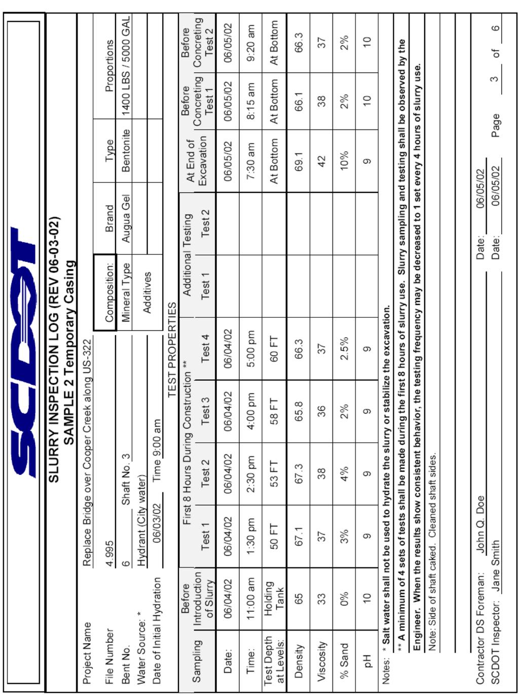
10 HOW TO COMPLETE THE SLURRY INSPECTION LOG Heading: - Fill in before drilling starts. - The Project Resident Engineer will sign approval line. 2. Slurry Data: - Fill in appropriate brands, types, and proportion. 3. Test Data: - Record test data as the testing Inspector performs the tests. - Note the depth at which the samples were obtained. - Make sure that a minimum of 4 tests are performed within the first 8 hours of slurry use. 4. Notes: Record any unusual events or results. 5. Fill in Contractor Representative and State Inspector. Fill in every blank on the form. If it does not apply put an N/A or a long dash. Use pencil but never erase. If you need to change something, strike a single line through the item and insert the correct information above it. If there is insufficient room to make a note, footnote the item and go to the bottom of the page, or use a separate page.

11
12
13 DRILLED SHAFT INSPECTION LOG (REV ) Project Name Page 4 of 6 File No. Bent No. Contractor Shaft No. Completed By Contractor DS Foreman - Date Station Reviewed By SCDOT Inspector - Date Offset Type of Drilling Fluid DS Location Variance at Top Bottom Cleanout Method Time/Date Final Cleanout Shaft Bottom Elev. Est. Shaft Bottom Dia. Shaft Plumbness Check/4' Rebar Cage: Proper # Vert. Bars Proper # Horiz. Bars Side Spacers Bottom Spacers Ties & Connections * Based on Compass Direction Inspected By: Visual Sounding N * Time Test Started Test just prior to placing Rebar cage (inches) Time Test Finished Test just prior to placing concrete (inches) Time Test Started * Direction Time Test Finished W * E * Note: 50% of base shall have < 1/2 Inch of sediment. No area of shaft bottom shall be more than 1 1/2 Inches. Notes Comments/Recommendations S * Results: Satisfactory DS Foreman Unsatisfactory SCDOT Inspector Time Date NOTE: Specification Tolerances - Location Variance at Top = 3 inches Max. Vertical (Plumbness) = 1 inch per 4 Ft. Max.
14 HOW TO COMPLETE THE DRILLED SHAFT INSPECTION LOG Fill in every blank on the form. If it does not apply put an N/A or a long dash. Use pencil but never erase. If you need to change something, strike a single line through the item and insert the correct information above it. If there is insufficient room to make a note, footnote the item and go to the bottom of the page, or use a separate page Heading: -Fill in before drilling starts. -Be sure to print your name and the start date of drilling. -The Project Resident Engineer or designated representative will sign approval line. 2. Shaft Status: Drill Fluid Check Responsibility of Contractor. Record density check performed by Contractor or Inspector. Type of Drill Fluid record a) Natural b) Mineral (commercial) c) Plain water Remember: Polymer slurry not allowed -Bottom Cleanout Method: Observe and record equipment type (i.e., cleanout bucket, air lift, submersible pump, etc.). Must match Installation Plan. -Time/Date Final Cleanout: Record when last cleanout performed prior to rebar cage placement. -Shaft Bottom Elevation Use weighted tape to measure; record. -Estimate Shaft Bottom Diameter record auger diameter. 3. Cage Check: -Reinforcing cage usually checked by others. -Proper number of Vertical bars count and record # of vertical bars in hole; compare to plan. -Epoxy you should never see coated rebar 4. Shaft Cleaniness: check procedure being used, record 1) Using S.I.D., visually inspect the shaft bottom in each of a minimum of 5 locations as shown on form. 2) Using a weighted tape, sound the shaft in each of a minimum of 5 locations as shown on form. Feel for hard bottom it translates to clean hole. Remember specifications. 5. Record Results:
15
16
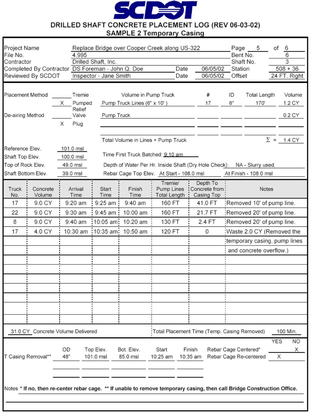
17 DRILLED SHAFT CONCRETE PLACEMENT LOG (REV ) Project Name Page 5 of 6 File No. Bent No. Contractor Shaft No. Completed By Contractor DS Foreman - Date Station Reviewed By SCDOT Inspector - Date Offset Placement Method Tremie Volume in Pump Truck # ID Length Volume Pumped Pump Truck Lines De-airing Method Relief Valve Pump Truck Plug Cap Total Volume in Lines + Pump Truck Σ = Reference Elev. Shaft Top Elev. Time First Truck Batched: Top of Rock Elev. Depth of Water Per Hr. Inside Shaft (Dry Hole Check) Shaft Bottom Elev. Rebar Cage Top Elev. At Start - At Finish Truck No. Concrete Volume Arrival Time Start Time Finish Time Tremie Depth Depth To Concrete Notes Concrete Volume Delivered Total Placement Time (Temp. Casing Removed) OD Top Elev. Bot. Elev. Start Finish Rebar Cage Centered* T Casing Removal** Rebar Cage Re-centered YES NO Notes * If no, then re-center rebar cage. ** If unable to remove temporary casing, then call Bridge Construction Office.

18 HOW TO COMPLETE THE DRILLED SHAFT CONCRETE PLACEMENT LOG 1 Fill in every blank on the form. If it does not apply put an N/A or a long dash Use pencil but never erase. If you need to change something, strike a single line through the item and insert the correct information above it. If there is insufficient room to make a note, footnote the item and go to the bottom of the page, or use a separate page Heading: -Fill in before drilling starts. -Be sure to print your name and the start date of drilling. -The Project Resident Engineer or designated representative will sign approval line. 2. Indicate correct Placement and Deairing method. 3. Compute and fill in Concrete Volumes: V = (πd 2 /4) x L 4. Fill in as much as possible prior to pour. 5. Record Truck number and amount of concrete. 6. Time: -May be military or standard clock. Be consistent and correct. Watch for date changes on late night pours. 7. Depths: -Tremie embedment may be measured by markings on the tremie. Depth to concrete may be measured by weighted tape. 8. Notes: Record any unusual events or items. 9. Casing/Rebar Data: -The rebar cage fabrication will normally be performed on-site. Observe the lifting to make sure deformation or damage does not occur (especially to CSL tubes). Check that the correct cage is being used. Check reinforcing steel diagram against the actual cage to be sure cage is correct. When the cage is being placed, observe the spacing to assure the cage is set to the proper elevation.

19
20
21 DRILLED SHAFT CONCRETE VOLUMES LOG (REV ) Project Name Page 6 of 6 File No. Bent No. Contractor Shaft No. Completed By Contractor DS Foreman - Date / / Station Reviewed By SCDOT Inspector - Date / / Offset Concreting Curve Depth (ft) Concrete Volume Placed (cy) Volume Delivered VD cy Volume In Pump Truck + Lines VPTL cy Volume of CSL Tubes VCSLT cy Wastage VW cy Volume Placed = VD-VPTL-VCSLT-VW = VP cy Theoretical Volume VTh cy Over Pour (VP-VTh =/> 1.00) OP cy Under Pour (VP-VTh < 1.00) UP cy
22 HOW TO COMPLETE THE DRILLED SHAFT CONCRETE VOLUMES LOG 1 Fill in every blank on the form. If it does not apply put an N/A or a long dash. Top of Shaft Trouble Territory! 2 Use pencil but never erase. If you need to change something, strike a single line through the item and insert the correct information above it. If there is insufficient room to make a note, footnote the item and go to the bottom of the page, or use a separate page. Bottom of Shaft Theoretical Line 1. Heading: -Fill in before drilling starts. -Be sure to print your name and the start date of drilling. -The Project Resident Engineer or designated representative will sign approval line. 2. Concrete curve: -compute Theoretical Volume of Concrete based on shaft size: Vth =(πd 2 /4)x L -locate points based on known cubic yards of concrete placed at measured bottom depth. -must be plotted during concrete placement. Note: Plotted line should closely parallel Theoretical line. There is a problem if: - a point plots way above or below the Theoretical line and/or - there is a significant rise or fall in an otherwise straight line (change in slope of line).
23
24