SIPA Technical Committee Update SIPA Annual Meeting & Conference Jacksonville, FL February 26-28, 2018
|
|
|
- Silvester Arron Patterson
- 5 years ago
- Views:
Transcription
1 SIPA Technical Committee Update SIPA Annual Meeting & Conference Jacksonville, FL February 26-28, 2018 Technical Committee Chair: Tom Williamson, Timber Engineering, LLC Presenter : Corey Nigh, NTA
2 Agenda 1) Call to Order and Welcome 2) Restraint of Trade Statement 3) Review and Approval of minutes of last TAC meeting (November ) 4) Overview of joint FPL/SIPA test programs 5) NTA/SIPA Design Guide for SIPs 6) ASTM D Standard development 7) SIP changes to the 2018 IRC 8) Revision of PRS ) Revision of APA/SIPA SIP Product Guide 10) Mississippi State University study on lignin-based polyurethane core material for SIPs 11) Canadian SIP Research 12) Adjournment and next meeting
3 Administrative Call to Order and Welcome Restraint of Trade Statement Review and Approval of minutes of last TAC meeting (November 30, 2017)
4 Review of Joint FPL/SIPA Research Projects FPL/SIPA creep testing project Phase I Pilot Study Phase II Study FPL/SIPA lateral load testing Phase I testing of SIP shear wall performance Phase II testing of SIP diaphragm performance FPL/SIPA aspect ratio and walls with openings testing
 was observed after 90 days of creep loading and 30 days of")
5 Creep Testing APA/FPL/SIPA Pilot Study FPL: $40,000 APA: $5,000 SIPA: Test panels Results published as FPL Research Note FPL RN 0332 No significant strength loss (Pmax) was observed after 90 days of creep loading and 30 days of unloading
 and moment critical loading")

6 Phase I Pilot Study Creep Testing Results 11% of Pmax 22% of Pmax 33% of Pmax Specimens tested under both shear critical (APA) and moment critical loading (FPL) configurations using 3 load levels as shown Recovered approximately 95% of the creep deflection after 30 days relaxation Results led to Phase II test program
7 Phase II /2016 Joint FPL/SIPA Creep Testing of SIPs Test Matrix Test # Sample Depths Sample Width(a) Span(a) Load Level # of Sample s Duration 1 6-1/2 in. 12 in To failure 28 1 min. 1a 6-1/2 in. 12 in lbs days /4 in. 12 in To failure 28 1 min. 2a 12-1/4 in. 12 in lbs days FPL: $100,000 SIPA: Test Panels


8 Phase II FPL/SIPA Creep Testing of SIPs Short Term Bending Tests Short term bending testing of twenty-eight 12-1/4 deep specimens and twenty-eight 6-1/2 deep specimens completed to determine test loads for creep testing


9 Phase II FPL/SIPA Creep Testing of SIPs Failure Modes - Short Term Bending Tests The static bending tests typically failed in shear at the manufactured discontinuities in the EPS web. The industry published design values for both depths and spans evaluated are controlled by shear and this supports the validity of the test data.
10 Phase II FPL Creep Testing of SIPs Short Term Bending Tests Control Specimens Pre-Creep 6-1/2 Quantity 28 PMax (lbf) Mean Standard Deviation % PE = mean * std. dev % PTL with 75% confidence = mean * std. dev Pre-Creep 12-1/4 Quantity 28 Mean Standard Deviation % PE = mean * std. dev % PTL with 75% confidence = mean * std. dev Creep Test Load = Pmax/3 ~ 350 lbs

11 Phase II FPL Creep Testing of SIPs 90 day testing of twentyeight 12-1/4 deep specimens and twenty-eight 6-1/2 deep specimens under creep load completed + 30 days with load removed
12 Phase II FPL Creep Testing of SIPs 12-1/4 Creep Deflection Curves

13 Phase II FPL Creep Testing of SIPs 12-1/4 Creep Recovery Curves
14 Phase II FPL Creep Testing of SIPs 6-1/2 Creep Deflection Curves
15 Phase II FPL Creep Testing of SIPs 6-1/2 Creep Recovery Curves
16 Phase II FPL Creep Testing of SIPs Results Table 2. Results summary of SIPS testing Quantity Static failure load of control specimens (lb) Specimen Depth 12.25" 6.5" Deflection of control specimens at failure (in) Initial elastic deflection at start of creep test (in) Additional deflection due to creep behavior (in) Total deflection (in) Initial elastic recovery at removal of long-term load Additional recovery due to creep behavior (in) Total deflection recovered (in)
17 Phase II FPL Creep Testing of SIPs Results Table 3. Average test results as a comparison of deflection states Quantity Specimen Depth 12.25" 6.5" Creep deflection, as a percentage of initial elastic deflection 40% 31% Creep deflection, as a percentage of failure deflection 15% 13% 30-day creep deflection recovery, as a percentage of 90-day creep deflection Total deflection recovery, as a percentage of total creep test deflection Static bending strength of post-creep tested specimens as a percentage of control specimen strength Static deflection of post-creep tested specimens as a percentage of control specimen deflection 50% 62% 81% 90% 90% 103% 84% 112%
18 Modeling of Creep Behavior of SIPs Creep behavior for structural insulated panels (SIP) under flexural loading with respect to time was modeled by Taylor, et al. (1997 ASCE Journal of Structural Engineering) Taylor examined four distinct models for creep behavior: a three, four, and five element viscoelastic model, and a power model.

19 Modeling of Creep Behavior of SIPs Solid line is test data from 12-1/4 deep specimen Dotted line is power model Final report in process to be published 1 st quarter of 2018

20 SIPA/FPL/APA test program on effects of boundary conditions on SIP shear wall performance Project co-funded by: FPL : $40,000 APA : $8,000 SIPA : $5,000 in test panels Cyclic testing of twenty-six 8x8 wall assemblies and monotonic testing of three 8x8 wall assemblies completed in July, 2016
21 SIPA/ FPL/APA test program on effects of boundary conditions on SIP shear wall performance Test Variables Test protocol (monotonic and cyclic) Nail size for panel connection (8d Box vs. 8d Common) Nail spacing (6 inches, 4 inches, and 3 inches) Wall bearing type (wood vs. steel bearing) Spline type (block spline vs. 2-2x lumber spline) Number of panel joints (no joint, 1 joints, 2 joints, and 3 joints) SIP thickness (4-1/2 inches vs. 6-1/2 inches) Orientation of OSB facers (strength axis horizontal vs. vertical) Bottom plate washer geometry (square, large round, and small round)

22 SIPA/ FPL/APA test program on effects of boundary conditions on SIP shear wall performance *Monotonic Test to be conducted using ASTM E72 and ASTM E564

23 Basic Wall Test Setup
 nails spaced at 6 inches on center")
24 Basic Wall Test Photo Basic wall, 2 panels, inch-diameter (8d box) nails spaced at 6 inches on center on wall perimeter.

25 4 Panel Wall Test Photo Wall fabricated with four SIP pieces, 24 inches wide per piece. Perimeter nails of inch-diameter nails spaced at 6 inches on center.
 with 8d Common nails (Wall")
26 Example Cyclic Data Backbone curves comparing 8d Box nails (Wall 2a) with 8d Common nails (Wall 3a).
27 SIPA/ FPL/APA test program on effects of boundary conditions on SIP shear wall performance Test Results Test protocol (monotonic and cyclic): Testing based on ASTM E72 and ASTM E2126 resulted in similar ultimate loads. Testing based on ASTM E564 and ASTM E2126 resulted in similar deflection profiles, but the ultimate load from monotonic (ASTM E564) tests was approximately 12% lower than the cyclic (ASTM E2126) tests. There is not enough evidence to conclude that ASTM E564 will result in a significantly lower ultimate load than the other test methods. Nail size for panel connection (8d Box and 8d Common): Data showed that there was no practical difference in the ultimate load between SIP walls constructed with these two nail sizes. Nail spacing (6 inches, 4 inches, and 3 inches): Data showed that a decrease in nail spacing from 6 to 4 inches and from 6 to 3 inches on center resulted in an ultimate load increase of 27% and 58%, respectively.
28 SIPA/ FPL/APA test program on effects of boundary conditions on SIP shear wall performance Test Results Wall bearing type (wood and rigid steel bearing): Data showed that when SIPs bear on steel, as compared to SPF bottom plates, the ultimate load was reduced by approximately 15%. However, the effect of bearing plate types on cyclic performance parameters was not significant. Spline type (Block spline and 2-2x lumber spline): Data showed that the difference in the ultimate load is insignificant (less than 5%). Number of panel joints (no joint, 1 joint, 2 joints, and 3 joints): Data showed that the number of panel joints and the aspect ratio of the individual SIP segments clearly had an effect on the cyclic performance. The more number of joints, the higher the ductility capacity of the SIP walls. As compared to 1 panel joint, zero joint resulted in an increase of around 10% in ultimate load, while 2 and 3 joints resulted in a reduction of ultimate load of 11% and 17% respectively.
29 SIPA/ FPL/APA test program on effects of boundary conditions on SIP shear wall performance Test Results SIP thickness (4-1/2 inches and 6-1/2 inches): Data showed that the ultimate load is similar between SIP wall thicknesses of 4-1/2 and 6-1/2 inches (less than 7%). Orientation of OSB facers (strength axis horizontal and vertical): Data showed that cross-oriented (horizontally oriented) facers resulted in a marginal (approximately 10%) reduction in the ultimate load, as compared to vertically oriented OSB facers. Bottom plate washer geometry (square and round): Data showed no difference between large and standard round washers. However, the squared washers showed a 13% higher ultimate load. However, since the failure modes were often associated with the top plate, but virtually never associated with the bottom plate, the difference in the ultimate load between squared and round washers is recommended to be further studied.

30 SIPA/ FPL/APA test program on effects of boundary conditions on SIP shear wall performance Test Report FPL-GTR-251 published January 2018

31 HIRL/FPL/SIPA Test Program SIP Shear Walls: Cyclic Performance of High Aspect Ratio Segments and Perforated Walls Forest Product Laboratory Forest Service U.S. Department of Agriculture $100,000 Structural Insulated Panel Association Provided all SIP test panels HIRL Report published October 1, 2013 Report
32 HIRL/FPL/SIPA Test Program Results 1. The measured unit shear capacity for fully-anchored SIP shear wall segments ranged from 1,400 lb/ft to over 2,100 lb/ft depending on the segment s aspect ratio. 2. The unit shear wall capacity and stiffness of SIP shear wall segments decreased with an increased number of panels jointed with a spline connection. A 25 percent decrease in unit shear was observed for a 20-foot wall with four spline joints compared to an 8-foot wall with one spline joint. 3. The unit shear wall capacity of SIP shear wall segments decreases with an increased segment s aspect ratio with a 16 percent decrease for a 2-foot segment as compared to a 4-foot segment. 4. The test results indicated that perforated SIP shear walls closely follow the overall PSW method trend for both strength and stiffness and led to joint SIPA/FPL follow-up study.
33 FPL/SIPA Aspect Ratio and Walls with Opening Testing Extension of HIRL Study in 2013: SIP Shear Walls: Cyclic Performance of High Aspect Ratio Segments and Perforated Walls HIRL study demonstrated that a SIP perforated shear wall performs like a traditional perforated shear wall but more testing needed. FPL staff and SIPA member representatives developed study plan to incorporate testing of 54 SIP wall assemblies Testing completed in June 2017 FPL: $200,000 SIPA: All SIP Test Panels

34 FPL/SIPA Aspect Ratio and Walls with Opening Testing Test plan
35 FPL/SIPA Aspect Ratio Testing Configuration Aspect Ratio Width Height Anchor Bolts Only Anchors and Holddowns 1 1: Aspect Ratio Test Plan 2 2: : :

36 FPL/SIPA Aspect Ratio Testing

37 FPL/SIPA Aspect Ratio Testing


38 FPL/SIPA Aspect Ratio Testing 8x8 wall test with hold downs 8x8 wall test with anchor bolts
39 FPL/SIPA Aspect Ratio Testing Panel Replicate Peak Deformation (in) Peak Load (lbf) Width No. Positive Negative Positive Negative Average: Average: Average: Average:

40 FPL/SIPA Aspect Ratio Testing Comparison of APA and FPL tests for 8x8 walls

41 FPL/SIPA Aspect Ratio Testing Comparison of use of hold downs vs. anchor bolts only for 8x8 walls

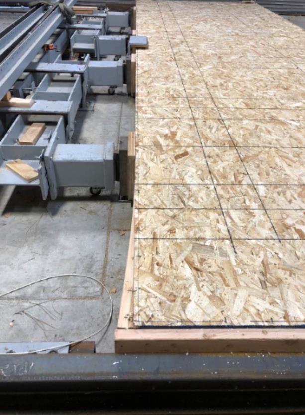
42 FPL/SIPA Walls with Openings Testing

43 FPL/SIPA Walls with Openings Testing

44 FPL/SIPA Walls with Openings Testing 8x20 wall with five 4x8 panels

45 FPL/SIPA Walls with Openings Testing 8x20 wall with single opening

46 FPL/SIPA Walls with Openings Testing 8x20 wall with two openings
47 FPL/SIPA Aspect Ratio and Walls with Openings Testing Current Status All testing completed in 2017 Initial aspect ratio testing results reported Preliminary analysis of walls with openings testing underway Final report anticipated in 3rd quarter of 2018
48 SIPA/FPL/APA test program on SIP diaphragm performance FPL $40,000 APA $8,000 SIPA $8, full-size SIP diaphragms of various configurations that will cover a range of variables as follows: 1. Effect of longitudinal SIP joint (no joint vs. 1 joint) 2. Effect of transverse SIP joint (no joint, 1 joint vs. 2 joints) 3. Inclusion of framing connections (with and without SIP screws) 4. SIP screw spacing (6 o.c. vs. 3 o.c.) between and within Series 1A and 5A
49 SIPA/ FPL/APA test program on SIP diaphragm performance Part I: SIP diaphragms without framing Objective: The purpose of this part is to evaluate the SIP diaphragm capacities without SIP screw connections to framing. Commonality for all test series in Part I: Assembly size: 8 x 24 SIP thickness: 8-1/4 Test Variables Fastener spacing to SIP plates: 8d cooler (2-5/16 x ) nails at 6 o.c. Test protocol: ASTM E455 (Monotonic)
50 SIPA/ FPL/APA test program on SIP diaphragm performance Test Variables Part I: SIP diaphragms without framing Series 1 (Base configuration) 1)SIP segment size: 8 x 24 2)Spline type: None 3)Number of tests: 1 Series 1 8' 24'
51 Transverse SIP joint Transverse SIP joint Transverse SIP joint SIPA/ FPL/APA test program on SIP diaphragm performance Test Variables Part I: SIP diaphragms without framing Series 2 4' Series 3 8' Longitudinal SIP joint 4' 12' 12' 24' Series 2 Series 3 Series 4 4' Series 5 4' Longitudinal SIP joint Longitudinal SIP joint 4' 4' 12' 12' Series 4 8' 8' 8' Series 5
52 SIPA/ FPL/APA test program on SIP diaphragm performance Test Variables Part II: SIP diaphragms with framing Objective: The purpose of this part is to evaluate the SIP diaphragm capacities with framing and framing screws. Commonality for all test series in Part II 1. Assembly size: 8 x SIP thickness: 8-1/4 3. Fastener spacing to SIP plates:8d cooler (2-5/16 x ) nails at 6 o.c. 4. Framing materials: 4x6 No. 2 or Better SPF 5. SIP screws: 3 o.c and 6 o.c. 6. Test protocol: ASTM E455 (Monotonic)
53 SIPA/ FPL/APA test program on SIP diaphragm performance Part II: SIP diaphragms with framing Series 1A (Base configuration) SIP segment size: 8 x 24 Spline type: None SIP screws: 6 o.c. and 3 o.c. (1 test each) Number of tests: 2 Test Variables 4x6 SPF framing Series 1A 24' 8'
54 Transverse SIP joint Transverse SIP joint SIPA/ FPL/APA test program on SIP diaphragm performance Test Variables Part I: SIP diaphragms with framing Series 2 Longitudinal SIP joint 4' 4' Series 3 8' 24' Series 2A 12' 12' Series 3A Series 4 4' Longitudinal SIP joint 4' 12' 12' Series 4A
55 Transverse SIP joint SIPA/ FPL/APA test program on SIP diaphragm performance Test Variables 4x6 SPF framing Part II: SIP diaphragms with framing Series 5A 4' Series 5A Longitudinal SIP joint 4' SIP segment size: 4 x 8 8' 8' 8' Spline type: Block spline for SIP joints SIP screws: 6 o.c. and 3 o.c. Number of tests: 2


56 Test 5A-3 4x8 segments 3 oc screw spacing SIPA/ FPL/APA test program on SIP diaphragm performance


57 Test 5A-3 4x8 segments 3 oc screw spacing Ultimate load 3347 SIPA/ FPL/APA test program on SIP diaphragm performance

58 SIPA/ FPL/APA test program on SIP diaphragm performance
59 SIPA/ FPL/APA test program on SIP diaphragm performance Part 1 Base diaphragm tests: Low value of 1186 using 8x24 segment with no joints High value of 1362 using 4x8 segments with longitudinal and vertical joints Average of 1242 with a COV of 8.4% Part 2 Diaphragm tests with SIP screws attached to test frame: 8x24 diaphragm with no joints 6 oc screw spacing oc screw spacing % increase 8x24 diaphragm with 4x8 segments with longitudinal and vertical joints 6 oc screw spacing oc screw spacing % increase
60 SIPA/ FPL/APA test program on SIP diaphragm performance

61 NTA/SIPA Design Guide for SIPs Design Guide development on schedule with NTA TAC Task Group review of Design Guide drafts completed Members of TAC invited to provide input to Design Guide TAC Task Group review of example software calculations underway
62 ASTM Standard on Structural Insulated Panels Draft document in process at ASTM D Section Committee level Standard development delayed due to other pressing industry activities After Section Committee level approval the standard will be balloted at the ASTM D07.02 Subcommittee level

63 SIP Changes to the 2018 IRC APA submitted numerous changes to the SIP section of the 2018 IRC based on conformance with the ANSI PRS standard. Changes reviewed and approved by SIPA TAC All changes were approved and are included in the 2018 IRC

64 Revision and Update of ANSI PRS Standards Committed reformed in 2017 Changes submitted to Secretariat (APA) 1st Revision ballot issued in November 2017 Committee resolving comments Goal is to have revised version ready for publication in 1 st quarter of 2018 Possible next step is to add roofs and floors

65 Revision and Update of APA/SIPA SIP Product Guide Last printed in 2007 Changes developed by SIPA staff working with TAC Task Group Changes submitted to APA for review in January 2018 Goal is to have revised version ready for publication in 1 st quarter of 2018
66 Mississippi State University study on lignin-based polyurethane core material for SIPs. Submitted to the USDA as a research proposal for funding of $250,000 under the 2016 Wood Innovations Funding Opportunity Project approved and work program initiated by MSU researchers in SIPA provided a letter of support for this research in the form of providing necessary SIP panels for testing and in-kind technical support.
67 Canadian SIP Research Research being conducted by NRA CAN Emphasis is on the study of the durability/longevity of SIP construction Also conducting static load tests of various SIP facers and foam cores Report Behavior of Structural Insulated Panels (SIPs) Subjected to Short-term Axial Loads submitted to ASCE Journal of Structural Engineering Canadian researchers agreeable to meeting with FPL staff and SIPA representatives to share research information but no time table set

68 Next meeting and Adjournment