Instruction Manual. DESIGNATION SPAN 500 Double Width EN /12 XXXD SPAN 500 Single Width EN /8 XXXD
|
|
|
- Rosamond Banks
- 5 years ago
- Views:
Transcription

1 Instruction Manual DESIGNATION SPAN 500 Double Width EN /12 XXXD SPAN 500 Single Width EN /8 XXXD CEN designation of this instruction manual EN 1298 IM en Rev-02


.")
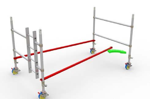
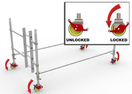
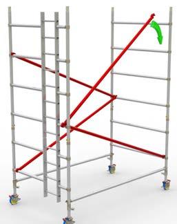
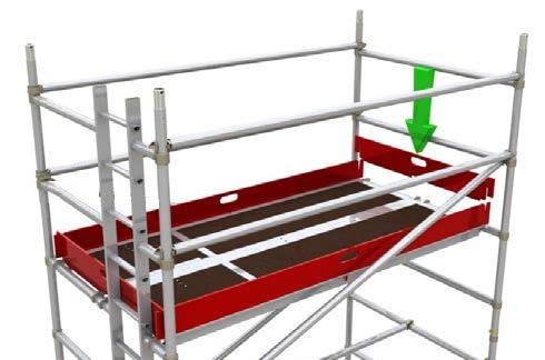
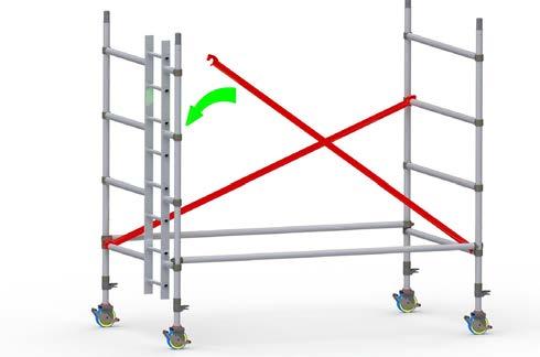
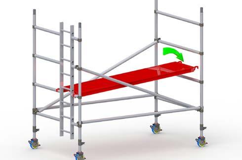
2 WARNING NEVER STAND ON AN UNGUARDED PLATFORM SAFE WORKING LOADS AND WORKING HEIGHTS The safe working load at each level of platform is 275kg evnly distributed, regardless of whether one or two platforms are installed. Therefore, even if two platforms are installed side by side, total cumulative load shall not exceed 275kg distributed. The total loading on the tower structure should not exceed 720kg. Normal maximum platform height for indoor use is 12m for Double Width, and 8m for Single Width. For outdoor use, the maximum height is 8m for Single and Double Widths. ASSEMBLY PROCESS 10cm 1. Preparation Locate the tower level adjusters on each leg at 10cm (4 inches) from the bottom of the leg. Unlock the interlock clips on all frames. When installed, always move the interlock clip to the locked position. Sort the braces into horizontal and diagonal braces - the diagonals are slightly longer. Unlock the brace locks. Unlocked Locked Unlocked Locked 2. Base Step 1: Install castor into adjustable leg. Step 2: Ensure interlock clips are released from the base frames (bottom frames). Step 3: Install castor / leg assembly to frame by pushing the leg into the frame tube. This should be done with manual force only, no tools. Step 4: Lock castors before ascending any part of the tower. Note the locking and unlocking position for the castors as shown here. Unlocked Locked 3. Locking down the platform (Windlock) A windlock clip is installed on the platform at the hook. This is locked as shown here. Unlocked Locked 02
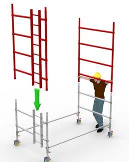
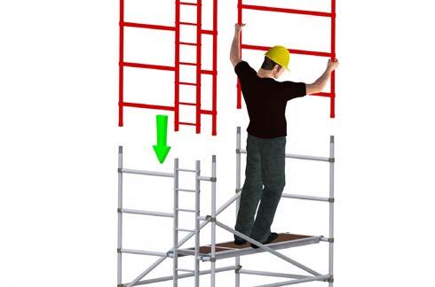
3 USAGE ADVICE We recommend a minimum of two people to assemble, dismantle and move the platform tower. Check that all components are on site and in good working order. Ensure that the assembly location is checked to prevent hazards during assembly, dismantling or moving and while working on the tower. Particular attention should be given to the ground condition, whether level or sloping, obstructions and wind conditions. The ground condition must be capable of supporting the tower structure. Towers must always be climbed from the inside of the assembly using the ladder. Adjustable legs must only be used to level the tower. If the adjustable legs are to be extended by more than 150 mm; a risk assessment needs first to be undertaken by a competent person. Lifting of components must be done inside the effective base area of the tower; components are normally hoisted using a rope. Moving the tower must only be done by manual effect from the base of the tower. When moving tower be aware of overhead hazards (e.g. electric cables). No personnel or material to be on the platform whilst the tower is being moved. Beware of horizontal loads which can lead to instability of the tower. The maximum side force is 20kg. When tying-in the tower, attach a tie to each upright at 4m height intervals. Ensure that couplers are suitable for 50mm diameter aluminum tube. Do not use boxes or steps to gain additional height. If extra height required, contact your distributor to get extra components. Do not lift or suspend an assembled mobile tower. Damaged components or components from other tower systems must never be used. Stabilisers should always be fitted when specified. Use the stabiliser shown on the component list according to the tower height. When wind exceeds Beaufort force 4, cease using the tower. If wind is expected to reach Beaufort force 6, tie tower to a rigid structure. If winds of Force 8 are forecast, dismantle the tower or remove to shelter. Wind speeds Force Peak mph Peak km/h Peak m/s Guidance Moderate breeze - raises dust & loose paper Strong breeze - difficult to use umbrella Gale force - walking is difficult CARE AND MAINTENANCE Keep all equipment clean, especially spigots and sockets where frames join. Spigots should fit easily into sockets. Lubricate with light oil. Remove dirt or paint from adjustable legs with a light brush, lightly oil the leg locks. Do not strike or hammer components. Do not throw or drop onto hard surfaces. Lightly oil spring mechanism of the hooks. For transport and storage, components are best stored vertically. Damaged parts must be repaired or replaced; refer to the Instant Upright website for further advice or contact your equipment supplier for advice. 03
4 MOVING TOWERS To Move the tower to a new position, first prepare the tower. Check that the wind speed does not exceed 29km/h (8.1m/s). Ensure the tower is empty (material and personnel). Check for overhead obstructions including electrical cables. Raise the stabiliser feet (only enough to clear obstructions). Taking care to ensure tower stability is maintained, insert any extended adjustable legs completely into the frame. Release the castor brakes. Carefully move the tower by manually applying force at the base. Do not use mechanical means to move the tower. Once positioned prepare the tower for use. Check and adjust as necessary to ensure all castors and stabilisers are in firm contact with the ground. Check that the tower is vertical using a spirit level. Reapply the castor brakes. EXPLODED VIEW Span double width Span single width 01. Castor 02. Adjustable Leg Rung Frame 04. Diagonal Brace 05. Platform Rung Frame 07. Toe-board set 08. Horizontal Brace Rung Ladder Frame 10. Clip Rung Ladder Frame 12. Stabiliser 04
5 STABILISERS Outriggers are to be used, when specified, to guarantee the structural stability of the tower. In addition, the ballast table is to be observed. Fig 2 Fig 3 Fig 4 ALWAYS ENSURE STABILISER SIZE IS CORRECT AND ABLE TO SUPPORT TOWER Lightly tighten the upper clamps above the third rung on each corner post. Position the lower clamp above the bottom rung. Ensure the lower arm is as horizontal as possible. Position the stabilisers so that the footpads are approximately equidistant from each other, as shown in Fig.2. Adjust the outrigger and reposition the clamps as required to make firm contact with the grou nd. Ens ure the clips with locking pi n are in place. W hen in th e correct position, tighten the clamps firmly. To position the tower against a wall, do not remove the stabiliser; move parallel with the wall. (Fig.3) To position the tower in a corner, remove the inside stabiliser and place the outside two parallel with the wall. (Fig.4) 05
6 SPECIFIC PRODUCT INFORMATION Table of parts and quantities Span 500 Double Width Towers - 2m, 2.5m and 3m lengths to EN1004 Platform Height (m) 2m 3m 4m 5m 6m 7m 8m 9m 10m 11m 12m Work Height (m) Tower Height (m) Tower Weight in kg (2m in length) Tower Weight in kg (2.5m in length) Tower Weight in kg (3m in length) Note: Quoted platform heights included 150mm (6 inches) leg adjustment for leveling that can be increased or reduced Description Weight (kg) 2m 3m 4m 5m 6m 7m 8m 9m 10m 11m 12m 4 Rung Frame Rung Ladder Frame Rung Frame Rung Ladder Frame Trapdoor Platform Fixed Platform Horizontal Brace Diagonal Brace Stabiliser (9030) Large Stabiliser (9090) Adjustable Leg Castor / Baseplate Toe-board set


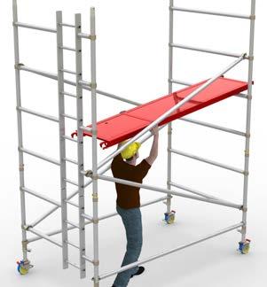
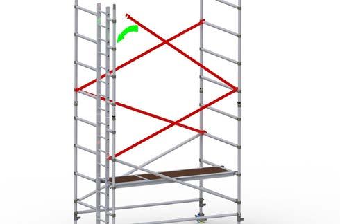
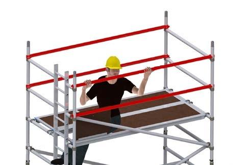
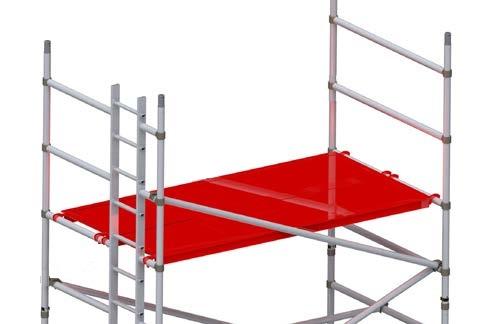
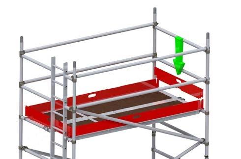
7 DOUBLE WIDTH TOWER - 6m


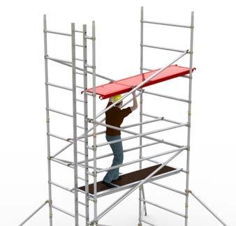
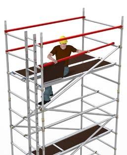
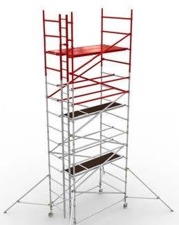
8 DOUBLE WIDTH TOWER - 6m st platform and horizontal braces reused for working platform


9 DOUBLE WIDTH TOWER - 5m


10 DOUBLE WIDTH TOWER - 5m st platform reused for working platform