Odd E. Gjørv. Norwegian University of Science and Technology, Trondheim, NORWAY
|
|
|
- Beatrice McCoy
- 5 years ago
- Views:
Transcription

1 Odd E. Gjørv Norwegian University of Science and Technology, NTNU, Trondheim, NORWAY 1
2 Durability and Service Life of Major Concrete Infrastructure 2
3 HISTORICAL BACKGROUND 1917: Extensive field investigations of concrete structures in US waters showed that steel corrosion was the big problem to the durability of the structures 3
4 HISTORICAL BACKGROUND (cont.) 1924: Atwood and Johnson had assembled a list of approximately references on durability of concrete in marine environments 4
5 HISTORICAL BACKGROUND (cont.) After 1924: Numerous investigations have been carried out in many countries and a large number of durabilty papers and recommen- dations have been produced 5
6 CURRENT FIELD EXPERIENCE Major concrete infrastructure in Norwegian marine environments - Concrete harbor structures - Concrete coastal bridges - Offshore concrete platforms 6

7 7
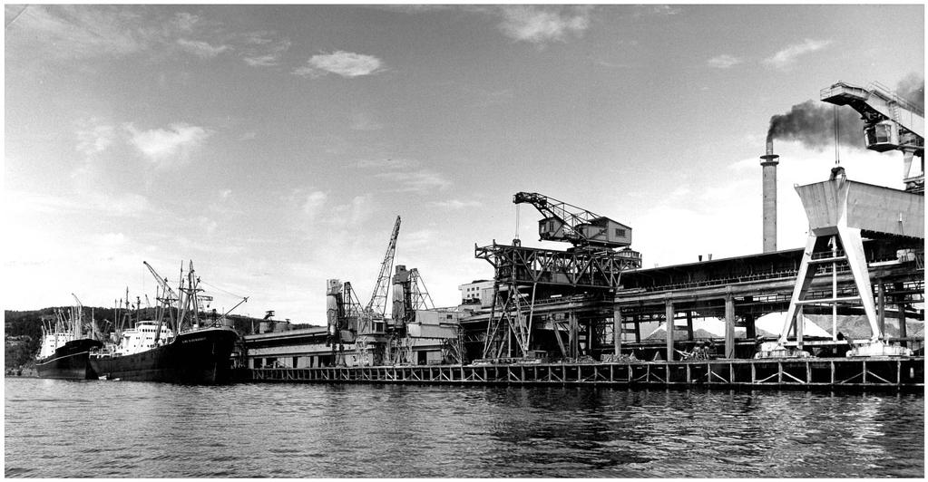
8 Concrete harbor structures Along the Norwegian coastline there are more than harbor structures, most of which are concrete structures which have typically started to corrode within a service period of about 10 years 8
9 9
10 Typical concrete harbor structure 10

11 11

12 12
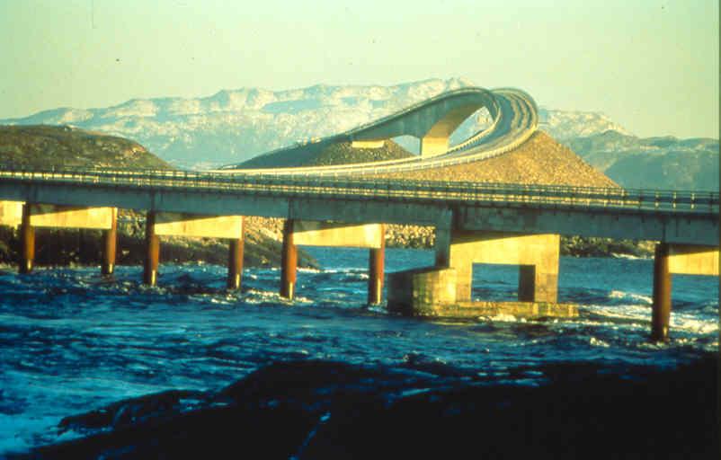
13 Concrete coastal bridges Along the Norwegian coastline there are more than 300 large concrete bridges built after 1970, of which more than 50% are corroding 13

14 14

15 15
16 16

17 17

18 18
19 Offshore concrete structures In the North Sea, 34 concrete platforms have been produced with high-performance concrete showing very good durability. However, still corrosion of embedded steel has caused some very costly repairs 19

20 20

21 21

22 22

23 23

24 24

25 25
")
26 Oseberg A Platform (1988): Repairs after 13 years (CP) 26
27 FIELD EXPERIENCE (cont.) For all the above concrete structures, chloride-induced corrosion has still been the most serious problem and threat to the operation and safety of the structures 27
28 FIELD EXPERIENCE (cont.) The achieved construction quality has typically shown a high scatter and variability, and any weaknesses and deficiencies have soon been revealed whatever durability specifications and materials have been applied 28
29 FIELD EXPERIENCE (cont.) Much of the observed durability problems can be ascribed due to poorly achieved construction quality and absence of proper quality assurance 29
30 FIELD EXPERIENCE (cont.) Descriptive durability requirements have been specified, the results of which are neither unique nor possible to verify and control for quality assurance during concrete construction 30
31 FIELD EXPERIENCE (cont.) During operation of the structures, the maintenance has typically been reactive. As a result, technically difficult and very costly repairs have been carried out 31
32 OFFSHORE vs. ONSHORE MARINE CONCRETE STRUCTURES Why have all the offshore concrete structures in the North Sea shown such a much better durability and performance than all the land-based marine concrete structures built during the same period? 32
33 SPECIFIED SERVICE LIFE Offshore concrete structures: - Typical 30 years increaseing up to 60 years Land-based marine concrete structures: - Typical 60 years increaseing up to 100 years 33
34 Offshore concrete structures When the first consept for use of concrete for offshore installations in the North Sea was introduced in the early 1970s, the international oil industry showed very great sceptisism 34
35 Offshore concrete structures (cont.) Current field experience with concrete structures in marine environments in the early 1970s clearly demonstrated that: - Corrosion problems typically ocurred after 5-10 years of service - The corrosion damage was very difficult to repair 35
36 Offshore concrete structures (cont.) The operators in the international oil industry were very demanding; safe operation with as little interuption as possible and high safety and security of all installations were of highest importance 36
37 Offshore concrete structures (cont.) In order to get acceptance for use of concrete in any offshore installation, much stricter durability requirements and procedures for quality assurance had to be applied 37

38 38
39 "FIP Recommendations" (1973) Durability requirements: - W/C 0.45 (0.40) - Min. cement content (C): 400 kg/m 3 - Nom. concrete cover: 75 (100) mm 39
40 The Norwegian field investigations of concrete harbor structures Construction period: ,000 m 2 concrete decks 5,000 tremie-cast concrete pillars 40

41 41
42 The Norwegian field investigations of (cont.) 84% of the structures had extensive steel corrosion First visible sign of corrosion after 5-10 years 34% of the structures had repairs with service life 10 years 42

43
44 Durability requirements: Offshore Apart from the first offshore concrete structure (Ekofisk-tank, 1973) which was produced with w/c = 0.45, all the other offshore structures have been produced with w/c =
45 Durability requirements: Onshore (1974,1976) Norwegian Committee on Concrete in Seawater FIP: w/c 0.45/0.40 (OD, DnV) ( 5 years) 1986 NS: w/c 0.45 (18 years) 1988 SVV: w/c 0.40 (20 years) 1996 SVV: w/c 0.38 (28 years) 2003 NS-EN 206-1: w/c 0.40 (0.45) (35 years)
46 CODES AND PRACTICE A very slow upgrading of codes and practice compared to the development of new knowledge and state of the art 46
47 CODES AND PRACTICE (cont.) It has taken more than 30 years for the European Concrete Codes to reach the same strict durability requirements as that specified for the first offshore concrete structures in the early 1970s 47
48 CODES AND PRACTICE (cont.) The durability requirements have been descriptive, the results of which have neither been unique nor possible to verify and control for quality assurance during concrete construction 48
49 INTERNATIONAL EXPERIENCE Annual bridge repairs in the USA : US$ mill : US$ bill : US$ bill. 9.4 Annual bridge repairs in Western Europe in 1998: US$ bill. 5 49
50 CHALLENGE TO THE CONSTRUCTION INDUSTRY Rapidly increasing proportions of limited construction budgets are being spent on costly repairs of existing concrete infrastructure rather on the production of new important infrastructure 50
51 CHALLENGE TO THE CONSTRUCTION INDUSTRY A more controlled and increased durability and service life of new concrete infrastructure are not only important from a cost point of view; it directly affects the sustainability of our society 51
52 ADDITIONAL REQUIREMENTS More and more owners are interested to invest somewhat more in order to obtain an increased and more controlled durability and service life beyond what is possible when only based on current standards; even small additional costs have proved to be an extremely good investment 52
53 Norwegian Association for Harbor Engineers (NAHE) "Recommendations for a more controlled and increased durability and service life of new marine concrete infrastructure" (TEKNA, Oslo, 2004) 53
54 Norwegian Association for Harbor Engineers (NAHE) (cont.) 2009: The third revised edition was also adopted by the Norwegian Chapter of PIANC 54
55 Norwegian Association for Harbor Engineers (NAHE) (cont.) In order to accomodate a high scatter and variability, the recommendations are based on a probability approach to the durability design ("DuraCrete", 2000) 55
56 Norwegian Association for Harbor Engineers (NAHE) (cont.) Greater control and improvements in durability also require the specification of performance-based durability requirements which can be verified and controlled for quality assurance during concrete construction 56
57 Norwegian Association for Harbor Engineers (NAHE) (cont.) The production of a service manual for future condition assessment and preventive maintenance of the structure is also an essential part of the durability design 57
58 Norwegian Association for Harbor Engineers (NAHE) (cont.) Strategy and approach: (1) Probability-based durability design (2) Quality assurance (3) Preventive maintenance 58
59 (1) Probability-based durability design A certain "service period " for the given concrete structure in the given environment is specified before the probability of corrosion exceeds 10% 59
60 (1) Probability-based durability design (cont.) As a result of the durability design, performance-based durability requirements are established: - 28-day chloride diffusivity (RCM) - Concrete cover 60
61 (2) Quality assurance The performance-based durability requirements are verified and controlled during concrete construction in order to achieve quality assuranace 61
62 (2) Quality assurance (cont.) From the quality control, documentation of achieved construction quality and compliance with the specified durability is obtained 62
63 (3) Preventive maintenance As part of the durability design, a service manual for monitoring and control of the future chloride ingress during operation of the structure is produced 63
64 (1) PROBABILITY-BASED DURABILITY DESIGN 64
65 Durability analysis - Time-to-corrosion analysis - Time-dependent reliability analysis Probability of corrosion (Construction quality) 65
66 Time-dependent reliability analysis Resistance Distributions Environment Time 66
67 Durability requirement For the given concrete structure in the given environment, a certain service period ( 150 years) is specified before the probability of steel corrosion exceeds 10% 67
68 Durability requirement (cont.) For service periods of more than 100 but less than 150 years: - Corrosion probability must be as low as possible ( 10%) - Additional protective measures are recommended 68
69 Durability requirement (cont.) For service periods of more than 150 years: - Corrosion probability must be as low as possible ( 10%) - Additional protective measures are required 69
70 Durability analysis A simple software (DURACON) has been established, primarily based on Fick s 2. Law of Diffusion in combination with a Monte Carlo Simulation 70

71 DURACON Software
72 Input parameters Environmental loading - Chloride loading (C S ) - Age at chloride loading (t ) - Temperature (T) Concrete quality - Chloride diffusivity (D) - Time dependence (α) - Critical chloride content (C CR ) Concrete cover (X) 72
73 (2) QUALITY ASSURANCE 73
74 Performance-based concrete quality control Control of chloride diffusivity Control of concrete cover 74
75 Chloride diffusivity (D 28 ) For the above durability analysis, the 28-day chloride diffusivity (D 28 ) is a very important input parameter which is being tested very rapidly independent of concrete age 75
76 Chloride diffusivity (D 28 ) (cont.) The chloride diffusivity (RCM) is a very important durability parameter reflecting the resistance of the concrete against chloride ingress 76
77 Chloride diffusivity (D 28 ) (cont.) The 28-day chloride diffusivity (D 28 ) is a very simple relative index reflecting both the density, permeability and mobility of ions in the pore system and hence, both the resistance to chloride ingress as well as the general durability properties of the concrete 77
78 Chloride diffusivity (D 28 ) (cont.) The 28-day chloride diffusivity (D 28 ) may be comparable to that of the 28-day compressive strength (f 28 ), which is also only a very simple, relative index primarily reflecting the compressive strength but also reflecting the general mechanical properties of the concrete 78
79 Chloride diffusivity (D 28 ) (cont.) For the above durability design, the 28-day chloride diffusivity (D 28 ) is an input parameter as important as the 28-day compressive strength (f 28 ) is for the structural design 79
80 Testing of chloride diffusivity Rapid chloride migration testing (RCM) (NT Build 492) + 80
81 Control of the 28-day chloride diffusivity (D 28 ) Regular control of the 28-day chloride diffusivity (D 28 ) has to be carried out during concrete construction 81
82 Relationship between diffusivity and electrical resistivity Nernst-Einstein: D = Z R.T 2.F 2 γ i t i.c.ρ i 1 D = k ρ 82
83 Calibration curve 83
 Steel plate Concrete R Steel")
84 Indirect control of the 28-day diffusivity based on the electrical resistivity (2-electrode method) Steel plate Concrete R Steel plate
85 Indirect control of the 28-day diffusivity based on the 4-electrode method 85
")
86 Control of in the in situ chloride diffusivity Control of in situ chloride diffusivity is based on testing of concrete cores from the construction site during the construction period (one year) 86
87 Control of the potential chloride diffusivity Control of the potential chloride diffusivity is carried out under controlled laboratory conditions (one year) 87
88 Development of chloride diffusivity 88

89 Control of concrete cover 89

90 Scanning equipment 90
91 Construction joints 91
92 Achieved construction quality Durability analyses based on achieved chloride diffusivity and concrete cover: (1) Compliance with specified durability (2) In situ construction quality (3) Potential construction quality 92
93 (3) PREVENTIVE MAINTENANCE 93
94 Control of future chloride ingress Even if the strictest durability requirements both have been specified and achieved, a certain rate of chloride ingress will allways take place during operation of the structures 94
95 Control of future chloride ingress (cont.) A regular monitoring and control of the real chloride ingress during operation of the structure must be carried out 95
96 Probability of corrosion Updated estimates on the probability of corrosion are made based on data from the observed rate of chloride ingress during operation of the structure 96
97 Probability of corrosion (cont.) Before the probability of corrosion becomes too high, appropriate protective measures measures must be implemented 97
98 PRACTICAL APPLICATIONS In recent years, the above Recommendations have been applied to a number of new commercial projects, one of which is shown as a Case Study in the following 98

99 Case Study: "Tjuvholmen" Oslo, (2010) 99
100 Tjuvholmen Oslo (2010) Owner s durability requirements: (1) Service life of 300 years (2) Documentation of achieved construction quality (NAHE) 100
101 Tjuvholmen Oslo (2010) (cont.) The project included a number of sea spaced concrete substructures: - In situ cast concrete structures for shallow water - Prefabricated concrete caisons for deep water 101

102

103 103

104 In situ cast structures 104

105 Prefabricated structures (dry dock) 105

106 106

107 107
108 EXECUTION OF WORK The whole project was carried out in two parts by two different contractors having two different strategies and approaches to the durability and service life of the structures 108
109 Contractor A: Probability-based durability design "NAHE Recommendations for a more controlled and increased durability and service life of new major concrete infrastructure in Norwegian harbors" (TEKNA, Oslo, 2004) Concrete structures No
110 Contractor A: Probability-based durability design (cont.) Service period of 150 years with a corrosion probability as low as possible ( 10%) Partly use of stainless steel reinforcement (W ) 110
111 Contractor A: Probability-based durability design (cont.) Established construction quality parameters: 1) 28-day chloride diffusivity (RCM): D x m 2 /s 2) Nom. concrete cover: 85 ± 10 mm 111
112 Contractor B: Descriptive durability requirements Current European concrete codes (NS-EN 206-1, 2003) + some additional requirements Concrete structures No
113 Contractor B: Descriptive durability requirements (cont.) 1) Concrete quality: - W/(C+k S) Binder content C 330 kg/m 3 (30% FA cement) - Silica fume S 4% by wt. of C - Air content 4% 113
114 Contractor B: Descriptive durability requirements (cont.) 2) Min. concrete cover : - Under water: 50 mm 70 mm - Over water : 60 mm 90 mm 3) Provisions for CP + embedded instrumentation for future chloride control 114
115 ACHIEVED CONSTRUCTION QUALITY - Compliance with specified durability - In situ construction quality - Potential construction quality 115
116 ACHIEVED CONSTRUCTION QUALITY (cont.) As a consequence of the required documentation of achieved construction quality, a performance-based concrete quality control also had to be carried out for the structures based on descriptive durability requirements 116
117 ACHIEVED CONSTRUCTION QUALITY (cont.) A regular control of both chloride diffusivity and concrete over had to be carried out for the structures based on the descriptive durability requirements 117
118 Control of chloride diffusivity (RCM) for all concrete structures Control of 28-day chloride diffusivity Control of chloride diffusivity on construction site (in situ) ( 1 year) Control of chloride diffusivity in laboratory (potential) ( 1 year) 118
119 Typical calibration curve for control of the 28-day chloride diffusivity (D 28 ) 119
120 Indirect control of the 28-day chloride diffusivity (D 28 ) 120
121 Control of concrete cover 121
122 ACHIEVED CONSTRUCTION QUALITY: Compliance 122
123 Compliance (Contractor A): Corrosion probability after 150 years (%) ( 10%) Structure Bottom Walls Deck No. slab
124 28-day construction quality (Contractor B): Corrosion probability after 150 years (%) Structure Bottom Walls Deck No. slab
125 Compliance (cont.) For all structures No. 1-4 (Contr. A) the specified durability was achieved with very good margin For all structures No. 5-8 (Contr. B) it was not possible to verify and control the specified durability 125
126 ACHIEVED CONSTRUCTION QUALITY: In situ quality ( 1 year) 126
127 Control of chloride diffusivity on construction site (in situ) Concrete cores from the given structures Concrete cores from corresponding dummy-elements 127

128 Production of dummy-elements 128

129 129

130
131 Development of chloride diffusivity on construction site and in laboratory 131
132 In situ quality (Contractor A): Corrosion probability after 150 years (%) Structure Bottom Walls Deck No. slab
133 In situ quality (Contractor B): Corrosion probability after 150 years (%) Structure Bottom Walls Deck No. slab
134 Achieved construction quality: In situ quality ( 1year) For all structures No. 1-4 (Contr. A) the corrosion probability was very low ( 0.001%) For all structures No. 5-8 (Contr. B) the corrosion probability was very variable and partly very high (0.6-70%) 134
135 ACHIEVED CONSTRUCTION QUALITY: Potential quality 135

136 Potential quality (Contractor A): Corrosion probability after 150 years (%) Structure Bottom Walls Deck No. slab

137 Potential quality (Contractor B): Corrosion probability after 150 years (%) Structure Bottom Walls Deck No. slab
138 Achieved construction quality: Potential quality For all structures No. 1-4 (Contr. A) the corrosion probability was very low ( 0.001%) For all structures No. 5-8 (Contr. B) the corrosion probability was also very low but much higher ( %) 138
139 SUMMARY (1) Probability-based durability design: - It was possible to select a very good durability for the given concrete structures in the given environment during the required period of service 139
140 SUMMARY (cont.) (2) Probability-based durability design: - For the durability desgn, it was possible to accomodate a high scatter and variability of all input parameters involved 140
141 SUMMARY (cont.) (3) Probability-based durability design: - It was possible to quantify how much of the black steel which was necessary to replace by stainless steel 141
142 SUMMARY (cont.) (4) Probability-based durability design: - Possible to quantify the performancebased durability requirements: - 28-day chloride diffusivity (D 28 ) - Concrete cover 142
143 SUMMARY (cont.) (5) Performance-based durability requirements: - Possible to detect and correct possible deviations during concrete construction; reduced scatter and variability of achieved construction quality were observed 143
144 SUMMARY (cont.) (6) Performance-based durability requirements: - Possible to document achieved construction quality - Possible to document compliance with specified durability 144
145 SUMMARY (cont.) (7) Descriptive durability requirements: - Not possible to verify and control specified durability - Higher scatter and variability of achieved construction quality were observed 145
146 SUMMARY(cont.) (8) Descriptive durability requirements: - Very difficult to argue about any weaknesses and deficiences which occurred during concrete construction as long as the requirement to compressive strength was still fulfilled 146
147 SUMMARY (cont.) (9) Documentation of achieved construction quality: - The required documentation of achieved construction quality distinctly clarified the responsibility of Contractor A for the quality of the construction process 147
148 SUMMARY (cont.) (10) Documentation of achieved construction quality: - The required documentation of achieved construction quality distinctly improved the workmanship giving reduced scatter and variability of achieved construction quality 148
149 SUMMARY (cont.) (11) Documentation of achieved construction quality: - For the owners it was very impor- tant to receive a documentation of achieved construction quality and com- pliance with the specified durability before the structures were formally been handed over from the contractors 149
150 CONCLUSIONS (cont.) (12) Service manual for preventive maintenance: - Upon completion of the structures, it was very important for the owner to receive a a service manual for regular condition assessment and preventive maintenance of the structures 150

151 151
152 Future development of Singapore City CRP Program Underwater Infrastructure and Underwater City of the Future ( ) To create space for the future development of Singapore City based on a large number sea spaced concrete substructures 152

153 153

154 154

155 155

156 156

157 157


158 158
159 159
160 160
161 161
162 CASE STUDY: Durability design of a marine concrete structure Durability requirement: A service period of 120 years with corrosion probability 10% Step 1: Selection of proper concrete quality (28-day chloride diffusivity) Step 2: Selection of proper concrete cover 162
163 Step 1: Four trial mixtures - W/(C+kS): Cement content 1) (C): 390 kg/m 3 - Silica fume content (S): 39 kg/m 3 (10%) 1) Four commercial types of cement (Type 1-4) 163
164 Step 1: Four trial mixtures (cont.) Types of cement: - Portland cement: Type 1 - Fly ash cement (18%): Type 2 - Slag cement (34%): Type 3 - Slag cement (70%): Type 4 164

165 Durability analysis - Step 1 165
166 Effect of cement type (w/b = 0.38) Temperature : 20 0 C 166
167 Effect of cement type (w/b = 0.38) Temperature : 10 0 C 167
168 Effect of cement type (w/b = 0.38) Temperature : 30 0 C 168

169 Durability analysis - Step 2 169
170 Effect of concrete cover (Type 1 Cement) 170