Hilton Baltimore Convention Center Hotel Western Podium
|
|
|
- Ezra Morris
- 5 years ago
- Views:
Transcription

1 Hilton Baltimore Convention Center Hotel Western Podium CHRIS SIMMONS Structural Option Faculty Consultant: Dr. Ali M. Memari Technical Report 1
2 TABLE OF CONTENTS EXECUTIVE SUMMARY. Page 3 INTRODUCTION.. Page 4 STRUCTURAL SYSTEMS FOUNDATION SYSTEMS Page 5 FLOOR SYSTEMS Page 6 ROOF SYSTEM. Page 7 LATERAL SYSTEM... Page 8 COLUMN SYSTEM... Page 8 APPLICABLE CODES. Page 9 MATERIALS AND PROPERTIES.. Page 10 LOADS DESIGN... Page 11 WIND... Page 12 SEISMIC. Page 17 SPOT CHECKS Page 20 CONCLUSION.. Page 22 APPENDIX WEIGHT CALCULATIONS. Page 24 Columns Page 27 Floor Slabs Page 29 Drop Panels.. Page 30 Total Floor Weight Page 30 SNOW. Page 31 WIND.. Page 32 SEISMIC. Page 34 SPOT CHECKS. Page 36 Page 2 of 41
3 EXECUTIVE SUMMARY The structural concepts and existing conditions report describes the structural system of the. This 21-story hotel, is located right in the heart of Baltimore next to Inner Harbor and Camden Yards, makes use of spread footings, caissons as a foundation, concrete flat plate slabs as well as concrete slabs with drop panels, reinforced concrete shear walls for the elevator shafts and stairwells, and a variety of sizes of concrete columns. Typical bay sizes are for the concrete columns are x 18-8 for exterior bays and x 19-7 for interior bays. Gravity and lateral loads were calculated using ASCE 7-05 and compared to the loads determined by RTKL Associates. The controlling lateral load was found to be the seismic force with a base shear, V=1146.9k. The wind force in the North/South direction had a base shear, V=939.71k, while the East/West direction had a base shear, V=165k. Spot checks were conducted on the beam 5-B16, and on the column L-11. These checks supported that the determination and accumulation of the gravity loads on this structure were comparable to those done by RTKL. The only columns that did not work while using ACI equation 10-2 were the column on the first floor and the mezzanine floor. Reasons for this are assuming that the tributary area was the same for all floors for that column and certain design loads used varied from the design loads used by RTKL. It is to be remembered that lateral forces were not included in these calculations. Page 3 of 41

4 INTRODUCTION The (HBCCH) is located right in downtown Baltimore next to the Baltimore Orioles stadium Camden Yards, and located blocks away from Inner Harbor. HBCCH is broken up into two podiums, East and West. The eastern podium is a 4-story building that houses a junior ballroom, meeting rooms and a multipurpose restaurant. The western podium is a 21-story building that houses the main hotel lobby, parking garage, grand ballroom with corresponding kitchen, meeting rooms, pool/health club, and 757 hotel rooms. The grand ballroom has moveable partitions located in the ceiling that allow multiple events to take place there. The western podium offers over 900,000 SF of hotel space. The structure of the western podium consists of concrete beams, columns and shear walls to resist lateral loading. The green roof above the grand ballroom is supported by special joists and while the pool above the grand ballroom is supported by steel beams. Page 4 of 41
5 Photo of Grand Ballroom. (Note Partition tracks in ceiling) FOUNDATION SYSTEMS The foundation of the western podium consists of caissons and spread footings. The spread footings will bear on firm natural soils and have a minimum bearing capacity of 4ksf. The drilled caissons will have straight shafts to bear on gneiss rock and have a minimum safe bearing capacity of 100ksf. The depths of the bottoms of the caissons vary from 14 feet all the way up to 32 feet below level B2 s floor slab. The compressive strength of the drilled caissons and spread footings are 3500 psi, while the caisson caps that the columns bear on have a compressive strength of 4000 psi. Page 5 of 41
6 Fig. 1 Typical Caisson Section FLOOR SYSTEM The floor system consists of two-way slabs whose thicknesses range from 8 thick on the floors with hotel rooms to 11 in the underground parking garage. The slabs shall are reinforced with 6x6-W1.4xW1.4 WWF, except for the slab-on-grade which is reinforced with 6x6-W2.1xW2.1 WWF as seen in Fig. 2. Drop panels are located on the B1, 1 st, Mezzanine level, 2 nd, 3 rd, and 15 th floors. The drop panels vary from 5 up to 11 in thickness. Typical spans for floors consisting of hotel rooms are Page 6 of 41

7 Fig. 2 Slab on Grade Detail ROOF SYSTEM As shown in Fig. 3, the roof system either type R-1 or R-2 roof construction. Type R-2 roof construction is used for the green roof above the grand ballroom and exercise room while type R-1 roof construction is used for the roofs located on the 15 th and 21 st floors. Fig. 4 shows the transition from the green roof assembly to the corresponding roof construction assembly. Fig. 4 Green Roof Transition Fig. 3 Roof Construction Details Page 7 of 41


8 LATERAL SYSTEM The lateral resisting system for wind and seismic loads consist of a number of steel brace frames that are located between the 3 rd floor and the 4 th floor roof. The load that is from wind and seismic is also transferred from each individual floor to the concrete beams and then to the concrete columns. A shear wall system is used as well for resisting wind and seismic loads. Shear walls are located around the elevator shafts and stairwells. COLUMN SYSTEM The layout of the column system is a very uniform layout consisting of typical exterior bays of x 18-8 and interior bays of x All columns consist of either a gravity resisting member or a combination of lateral and gravity resisting members. Column sizes vary from 12 x 18 columns to 44 x 30 Columns. Sloped columns can be found on the second and third floors of the western podium. A typical framing plan is shown in fig. 5. Fig. 5 Typical Framing Plan Page 8 of 41
9 APPLICABLE CODE Design Codes used for Original Design: International Building Code, 2000 Edition City of Baltimore Code American Society of Civil Engineers (ASCE) o ASCE 7 05, Minimum Design Loads for Buildings and Other Structures American Institute of Steel Construction (AISC) o Steel Construction Manual, 13 th Edition (LRFD) American Concrete Institute (ACI) o Building Code Commentary Code Substitutions/ Additional References used for Thesis Design: International Building Code, 2006 Edition Reinforced Concrete: Mechanics & Design, Fifth Edition o By: James K. Wight, James G. MacGregor Page 9 of 41
10 MATERIALS AND PROPERTIES Steel: W and WT Shapes A992 Channels A36 Angles A36 Rectangulare & Square HSS A500 Grade B Round HSS A500 Grade B Steel Pipe A53, Grade B Steel Plates A36 Steel Bars A36 High Strength Bolts A325 or A490 Anchor Bolts F1154 Grade 36 Standard Fasteners A307 Concrete: Drilled Caissons Spread Footings Grade Beams & Caisson Caps Typical SOG Columns Shear Walls Normal Weight Slab on Metal Decc f c = 3500 psi f c = 3500 psi f c = 4000 psi f c = 4000 psi f c = 4000 psi f c = 4000 psi f c = 3500 psi Reinforcement: Composite Floor Deck A611 Grade C Min. A653 Quality SS Grade 33 Roof Deck A653 Quality SS Grade 33 Deformed Bars A615 Grade 60 Deformed Bars (weldable) A706 Welded Wire Fabric A185 Note: Material strengths are based on American Society for Testing and Materials (ASTM) standard ratings. Page 10 of 41

11 DESIGN LOADS All of the design loads for this technical report werr calculated referencing ASCE 7-05: Minimum Design Loads for Buildings and Other Structures. All dead, live and snow loads can be seen in Table 1 below. Almost all lateral loads were calculated by hand and inserted into the tables on the following pages. The hand calculations can be found on pages in the Appendix. After calculating the lateral loads it was concluded that Seismic controlled over Wind. Page 11 of 41

12 WIND LOADS Wind loads were determined using ASCE 7-05 Section 6.5. Section 6.5 describes Method 2-Analytical Procedure. The variables used in this analysis are located below in Table 2a and these values are supported by base calculations which are located in the Appendix on pages 32 and 33. Page 12 of 41


13 Table 2b was developed to determine the wind pressures in the North/South direction as well as the wind pressure on the parapet. Figure 6 shows both the windward and leeward pressures on the building. Page 13 of 41
14 Fig. 6 North/South Wind Pressures Page 14 of 41

15 Table 2c was developed to determine the wind pressures in the East/West direction. Figure 7 shows the windward and leeward pressures on the building. Page 15 of 41
16 Fig. 7 East/ West Wind Pressures Page 16 of 41

17 SEISMIC LOADS In order to calculate the seismic forces on HBCCH, Chapters 11 and 12 were referenced from ASCE HBCCH was assumed to have a rigid diaphragm which allowed for the use of the Equivalent Lateral Force Procedure found in Section 12.8 of ASCE The variables used in this procedure are located in Table 3a. Page 17 of 41

18 The seismic design variables Z, I, S, R w, h n, and C can be found in the Appendix on pages 34 and 35. Figure 8 shows the story forces and the story shear found during seismic design. Page 18 of 41
19 Fig. 8 Seismic Design Diagram Page 19 of 41

 and column L-11 (Figure 10). Fig.")
20 SPOT CHECKS In order to verify that the loads determined via Technical Report 1 were reasonable and adequate, spot checks of typical framing were conducted. These spot checks were imperative in being able to compare the calculations done in this report to the design of HBCCH by RTKL. Only gravity loads were applied during these calculations and therefore at least some variation could be attributed to the fact that lateral loads will also be present and require inclusion in analysis. The typical framing elements were taken from Floor 5 and include a check of beam 5-B16 (Figure 9) and column L-11 (Figure 10). Fig. 10 Column L-11 (Column is highlighted) Fig. 9 Beam 5-B16 (Beam is highlighted) Page 20 of 41


21 Page 21 of 41
22 CONCLUSION After examination of the existing structural system and calculations of various gravity and lateral loads of the, it was found that the hotel was adequately designed to withstand these forces. Through the use of ASCE 7-05 to calculate wind loads via Method 2 and seismic loads via the Equivalent Lateral Force Procedure, the controlling force was Seismic with a base story shear, V= k. Spot checks done on beam 5-B16 and the exterior column L-11 on floor five also proved that the determination and accumulation of loads done within this report were comparable to those completed by RTKL. These two components were found to be satisfactorily designed. The only discrepancy found was for the first floor and mezzanine column L-11. This could ve been because of differences in values for loads or because of a difference in tributary area calculated for those two columns. Also due to not including lateral forces in the calculations larger moments would be added to the columns and beams. As research continues for Hilton Baltimore Convention Center Hotel lateral forces will be taken into account and will have an effect on the framing, shear walls and foundations. Page 22 of 41
23 APPENDIX Page 23 of 41
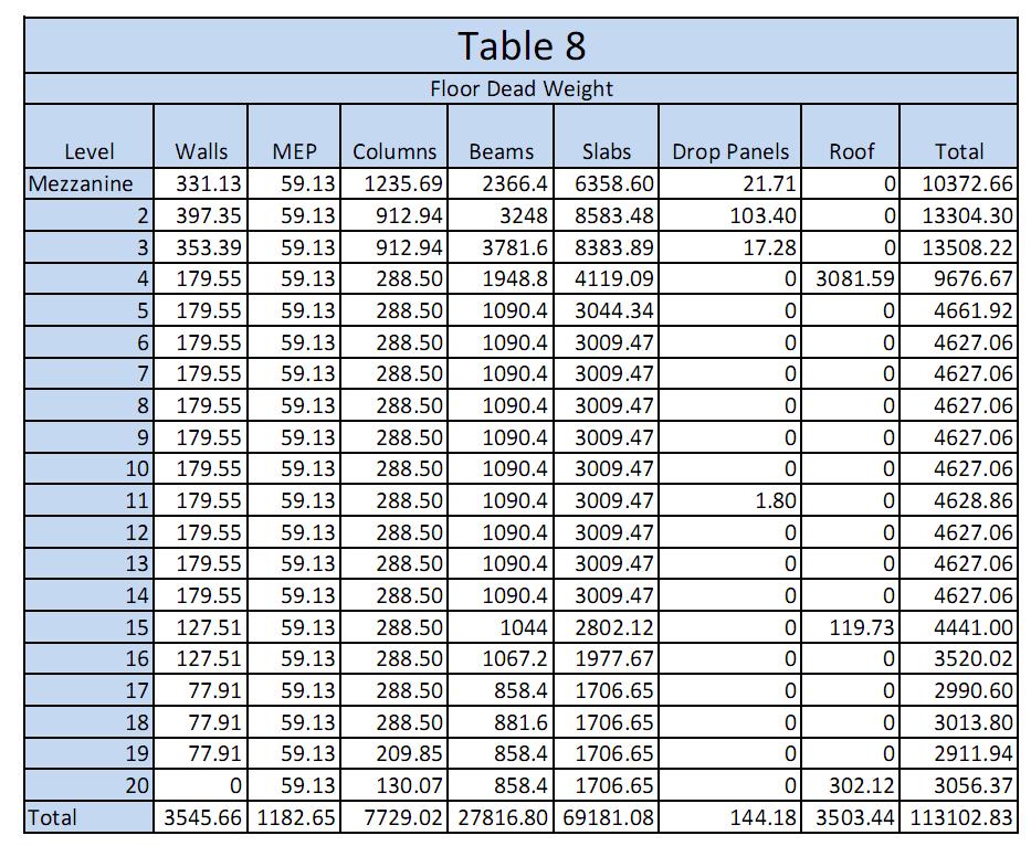
24 DEAD WEIGHT CALCULATIONS Page 24 of 41
25 Page 25 of 41
26 Page 26 of 41

27 Page 27 of 41

28 Page 28 of 41

29 Page 29 of 41

30 Page 30 of 41
31 Page 31 of 41
32 Page 32 of 41
33 Page 33 of 41
34 Page 34 of 41
35 Page 35 of 41
36 Page 36 of 41
37 Page 37 of 41
38 Page 38 of 41
39 Page 39 of 41
40 Page 40 of 41
41 Page 41 of 41