Preliminary Geotechnical Report
|
|
|
- Samson Fox
- 5 years ago
- Views:
Transcription
1 Preliminary Geotechnical Report Trunk Highway 101 from Pioneer Trail to Lyman Boulevard Chanhassen, Minnesota SEH No. CHANH March 14, 2011
2
3 Table of Contents Certification Page Table of Contents 1.0 Introduction Background Summary of Recommendations Subsurface Investigation Subsurface Exploration Soil and Groundwater Conditions Existing Road Embankment and Pavement Conditions Off Road Borings/Soil Conditions Groundwater Conditions and Piezometers Geotechnical Recommendations Subgrade and Pavement Design Soil Correction and Special Embankment Construction Embankment from Station to , SB Embankment from Station to , SB Station to SB Embankment from Station to , SB Retaining Walls Recommendations for Additional Drilling, Testing and Analysis... 7 Page List of Tables Table 1 Boring Location Summary... 2 Table 2 Soil Correction... 5 Table 3 Recommended Borings and Testing for Retaining Walls... 8 Table 4 Recommended Borings and Testing for Widened Embankment Sections... 8 Figure 1 TH 101 Central Alternative, BOR 1 Figure 2 TH 101 Central Alternative, BOR 2 List of Figures Appendix A List of Appendices Braun Intertec Report Results of Soil Borings and Laboratory Testing SEH is a registered trademark of Short Elliott Hendrickson Inc. Preliminary Geotechnical Report CHANH City of Chanhassen Page i
4 March 2011 Preliminary Geotechnical Report Trunk Highway 101 from Pioneer Trail to Lyman Boulevard Prepared for City of Chanhassen, Minnesota 1.0 Introduction 1.1 Background The section of Trunk Highway 101 between Lyman Boulevard and Pioneer Trail in Chanhassen, Minnesota is being considered for widening and horizontal alignment changes to improve safety. The project is currently in the preliminary design stages to define the alignment. A preliminary subsurface investigation is being performed in two phases to assist with preliminary design of the corridor. This report discusses the results of the first phase of the subsurface investigation. The purpose of the first phase of the subsurface investigation was to obtain soils information to assist in selection of the road alignment. In addition, it was the goal to identify areas that require additional subsurface investigation and soil testing. All of the recommendations contained within this report should be considered preliminary and are to be used for planning purposes. Additional phases of drilling and testing are required to refine the recommendations such that they can be used for final design and development of plans and specifications. 1.2 Summary of Recommendations The following is a summary of recommendations for the preliminary design. More detail with respect to these recommendations is provided within the Geotechnical Recommendations section of this report. 1. An R-value of 5 is recommended for pavement design. This is representative of existing clay subgrade soils and anticipated fill for the road embankment. 2. The pavement section is recommended to consist of 8.5 of bituminous pavement, 12 of Class 5 aggregate base course, and 18 of select granular borrow (modified P200 < 10%) 3. Drain tile is recommended for the entire road section. 4. Soil correction consisting of complete muck excavation and partial muck excavation with a surcharge will be required west of the existing road embankment due to widening from Stations to , SB and Stations to , SB. Depths of soil correction range from 4 to 12 feet. 5. Retaining walls up to 19 feet in height are being proposed for the project. Two of the walls are assumed to be cast in place concrete, while the remaining walls are assumed to be mechanically stabilized earth retaining systems with concrete blocks or panel facia. CHANH Page 1
5 6. Additional drilling and testing will be required for completion of the preliminary design phase and for final design. The additional drilling is intended to obtain the necessary soil parameters for design of retaining walls, further definition of muck excavation, evaluation of slope stability and settlement, and design of the surcharge. 2.0 Subsurface Investigation 2.1 Subsurface Exploration The proposed exploration program consisted of 20 soil borings ranging in depth from 5 to 30 feet. Two temporary piezometers were proposed to be installed at the locations of Borings 12 and 18 for the purpose of monitoring the groundwater; however, only one was installed since the other location was inaccessible due to snow conditions. A summary of the boring locations and depths is provided in Table 1. The first phase of the subsurface investigation is complete as of January 27, 2011, with the exception of one piezometer. The boring logs, testing results, and location map are included in the report prepared by Braun Intertec, Results of Soil Borings and Laboratory Testing, which is included as Appendix A to this report. Please note that Braun Intertec uses a prefix of ST- for each boring. This represents a standard penetration test boring. For this investigation a calibrated hammer was used to simulate an energy transfer efficiency of 60 to 70 percent, which is required per Mn/DOT s Consultant Specifications for Subsurface Investigation & Geotechnical Analysis and Design Recommendations. In this report the ST- prefix will be dropped when referring to the soil borings. Table 1 Boring Location Summary Boring Elevation Easting Northing Depth (feet) Comments Road boring Off road, ditch boring Road boring Off road, ditch boring Road boring Off road, ditch boring Road boring Off road, ditch boring Off road, swamp boring Off road, swamp boring Road boring Off road, swamp boring Off road, swamp boring Road boring Off road, Bandimere Park Road boring Off road, swamp boring Road boring Road boring Off road, ditch/trail boring Preliminary Geotechnical Report CHANH City of Chanhassen Page 2
6 3.0 Soil and Groundwater Conditions 3.1 Existing Road Embankment and Pavement Conditions Several borings were taken within the existing road to determine pavement section and road subgrade conditions. Some of the borings were extended beyond a depth of 6 feet due to proposed cut sections. Borings 1, 3, 5, 7, 11, 14, 16, 18, and 19 were taken within the existing road or shoulder. The subgrade soils were primarily clay, with occasional layers of silt loam, clay loam, loamy sand, and sandy loam. The soils are of glacial origin and are generally stiff; however, the moisture contents are quite variable. On average, the pavement section encountered is a total of 13 inches, approximately 6 to 8 inches of bituminous pavement over 5 to 9 inches of base course. There are some exceptions at the southernmost and northernmost borings, Borings 1, 3, 19. Bituminous pavement was 5 to 8 inches over 12 to 18 inches of a loamy sand with gravel. The loamy sand with gravel may classify as an aggregate base course. Two borings, Borings 15 and 20 were taken within existing trails. The bituminous thickness was recorded at 3.5 to 5 inches. The aggregate base course, consisting of loamy sand with gravel, was recorded at 7.5 to 18 inches. 3.2 Off Road Borings/Soil Conditions Several borings were drilled off of the existing alignment to investigate areas where the embankment is being widened or where the alignment is being shifted. Borings 2 and 4 were taken west of the existing embankment, south of West 96th Street. Borings 6, 8, 9, 10, 12, 13, and 17 were drilled in wetland areas where soft, compressible soil deposits were anticipated. Boring 15 was drilled in Bandimere Park to obtain information for evaluating a potential retaining wall. Finally, Boring 20 was drilled east of the existing embankment in a low area that will receive fill from the widened embankment. With the exception of Bandimere Park, the conditions encountered off road can be defined as existing ditch or wetlands. The existing ditch conditions are characterized by topsoil or very wet clay up to 2 feet in thickness. Underlying soils consist of clay or loamy soils that vary in consistency from soft to stiff. The existing ditch conditions are represented by Borings 2, 4 and 20. Wetland or organic deposits were expected to be encountered west of the existing embankment between West 96th Street and the north end of Bandimere Park, approximately Station to Borings 6 and 8, representing Station to , do not necessarily confirm the presence of wetland deposits; however, they do exhibit characteristics of thick, soft fill or topsoil placed over a wet area. Approximately 5 feet of topsoil fill exists at the toe of the embankment in this area. Underlying soils consist of clay loam and sandy loam, which is wet and gray in color, typically indicating a seasonally high groundwater table. The remaining area west of the existing road, from Station to , exhibits characteristics of wetland deposits. Typically, organic clay or silt was encountered over soft, clay alluvium or sandy loam. The thickness of the organic clay and silt was variable, approximately 2 to 7 feet. The underlying soft clay extended to depths of 4 to 19 feet below existing grade. Groundwater was measured at or near the ground surface. Preliminary Geotechnical Report CHANH City of Chanhassen Page 3
7 3.3 Groundwater Conditions and Piezometers It was initially recommended to install two piezometers on site. The piezometer at Boring 12 has been installed. The piezometer at Boring 18, near the underpass for the trail, has not been installed. This was due to the depth of snow in the area. A piezometer is still recommended in this area, but it will need to wait until spring. No water was recorded in Boring 18; however, there is a sand layer present that could become water bearing during wet periods. The screened interval for the piezometer is recommended to include the sand layer. Groundwater was encountered in several borings throughout the project. There appears to be a perched groundwater condition at Borings 2 and 19, elevations of and feet respectively. The water was recorded just above a sand layer that was encountered between clay and appeared to rise to the final recorded level after the auger penetrated the sand. Groundwater was also encountered in the borings located in the wetland west of the road between Stations and and ranged in elevation from 871 and 880 feet. Although groundwater was not encountered in Boring 15, located in Bandimere Park groundwater elevation, data obtained from Mn/DOT suggests that it is likely to exist in the slope above the road. The groundwater was monitored from September 2007 to February The elevation of the groundwater ranged from 889 to 898 feet. Further investigation is required in this area to assist with design of the proposed retaining wall, including any subsurface drainage features. The water level in the piezometer at Boring 12 was recorded on February 28, However, since the water table is so close to the surface of the ground it was found to be frozen. The top of ice in the piezometer was recorded at the ground surface. However, this reading could be erroneous due to expansion of water during freezing. Therefore, it is recommended to follow up with additional measurements in the spring. It is not unusual for the groundwater to exist near the ground surface in wetland areas. 4.0 Geotechnical Recommendations 4.1 Subgrade and Pavement Design The existing subgrade consists primarily of clay and silt and is poorly suited for support of pavement sections. This is evident from the results of the R-value test, which was performed on a sample from Boring 7. The R-value for the existing clay was determined to be 5. It is recommended to use a pavement design section that promotes drainage and incorporates the use of select granular which will help stabilize the subgrade during construction. It is anticipated that during wet weather the subgrade will become unstable, unless it is graded to promote drainage and well compacted. The design R-value for the project is 5, which is for the native clay subgrade soils that were encountered. It is also anticipated that the embankment sections requiring fill will use similar materials. The recommended pavement section consists of the following: 2.5 Bituminous Wear Course 6 Bituminous Binder/Base Course 12 Class 5 Aggregate Base Course 18 Select Granular Borrow The pavement design is based on 1.92 million cumulative ESALs, 20 year design, 2 lanes each direction, and an urban/metro traffic distribution. The ESAL calculation utilizes Preliminary Geotechnical Report CHANH City of Chanhassen Page 4
8 projected ADT for 2014 of 7,700 and 2034 of 12,500 vehicles and a metropolitan urban traffic distribution. The design requires a minimum GE or 40.1 for the project. It is also recommended to use a lateral subsurface drain on each side of the road. This should be installed the entire length of the project due to the poor drainage characteristics of the clay subgrade. Provide outlets to the storm sewer or to low areas outside of the road embankment. Groundwater does not appear to be present within the existing subgrade. However, there are several cuts proposed within the existing slope east of the road. These cuts range from 5 to 20 feet deep. Based on the groundwater monitoring completed by Mn/DOT in Bandimere Park it is likely to encounter saturated layers of sand or silt. It would be expected to encounter groundwater in these layers due to seasonal variations in precipitation. This will require the need to account for potential groundwater in the design of the retaining wall in this area and additional subsurface drainage considerations, which may consist of blanket or panel drains at the back of the excavation. A 10-foot cut is anticipated from Station to , NB. It should be anticipated to encounter localized seepage from the slope. This may require subsurface drainage to be deepened or inclusion of a trench drain within the slope. It is recommended to obtain additional subsurface information in these areas in order to address the design of subsurface drainage more thoroughly. 4.2 Soil Correction and Special Embankment Construction Soil correction is not anticipated for portions of the road constructed within the existing embankment. However, the recommended pavement section is 38.5 inches thick, including select granular borrow. This will require removal of existing subgrade soils. Several areas outside of the existing road embankment have been identified for soil correction. The soil correction will require removal and replacement with select granular borrow, modified (less than 7% passing the No. 200 sieve). For purposes of planning it is recommended to assume the groundwater at the ground surface for the locations listed in Table 2. Table 2 Soil Correction Location Offset Depth Soil Type / Comments Sta to , SB Variable 5 Clayey topsoil Sta to , SB Variable 4 Clayey topsoil, organic clay and soft clay alluvium Sta to , SB Variable 7 Organic clay and soft clay alluvium Station to , SB Variable 12 Organic clay and soft clay alluvium Since the new alignment has a variable offset from existing road centerline it is not possible to provide a uniform offset and consistent limit for each soil correction area. It is recommended to start at the existing shoulder and perform a stepped cut with an approximate slope of 1 horizontal to 1 vertical extending downward to the prescribed soil correction depth. Each step is recommended to be 2 feet or less in vertical height. The depth of the soil correction is measured from existing ground surface. Extend the soil correction outward to the slope intercept of the proposed embankment. Dewatering of the excavation will likely be necessary. In other areas where the embankment is widened removal of existing topsoil will be required. This is not included in Table 2; however, stripping of topsoil from existing Preliminary Geotechnical Report CHANH City of Chanhassen Page 5
9 slopes and ditches will be on the order of 18 to 24 inches. It is recommended to use 24 inches of stripping for estimating earthwork during preliminary design Embankment from Station to , SB This area is represented by Borings 2 and 4. Due to widening of the embankment, approximately 10 to 15 feet of fill will be placed west of the existing alignment. It is recommended to assess slope stability and settlement in the next phase of the preliminary design or during final design. This will require obtaining additional borings to 30 feet and obtaining soil samples for strength and consolidation testing. Mitigation of settlement and slope stability could include staged filling and placing surcharge fill. Muck excavation could be an alternative as well. However, the depth and limits would need to be identified in follow up subsurface investigation. This impacts the south bound lanes only Embankment from Station to , SB This area is represented by Borings 6 and 8. There is about 4 to 5 feet of clay fill soil described as black/topsoil or fill. This is possibly from previous road construction and was disposed of within the slope of the road embankment as was common practice. The borings were close to the toe of the existing slope. About a 5-foot soil correction will be required to remove the unsuitable clay/topsoil. Replacement fill can be on site clay soils provided the excavation is maintained in a dry condition. The excavation depth will vary from up to 2 feet within the existing slope to 5 feet outboard of the embankment toe. Due to widening of the embankment, approximately 10 to 15 feet of fill will be placed west of the existing alignment. It is recommended to let the embankment sit as long as possible prior to placement of curb and gutter or bituminous pavement. It is recommended to assess settlement in the next phase of the preliminary design or during final design to determine if mitigation measures are required Station to SB This area is represented by Borings 9, 10, 12, and 13. Organic clay and soft clay alluvium was encountered at depths 2 to 19 feet. For most areas the soft clay is in the range of 2 to 7 feet. The deepest area was found at Boring 13, which is includes a 5-foot layer of loose sandy loam. It is recommended to plan on limited muck excavation up to 7 feet, in combination with a surcharge. Replacement fill will need to consist of select granular borrow (modified to P200 less than 7%) due to placement below the water table. Since slope stability and settlement will still be an issue due to extensive fill for the embankment it is recommended to place fill in stages, perform a surcharge, and let the embankment sit for a period of time prior to paving. It would be required to perform a soil correction to a depth of 30 feet in order eliminate the need for a surcharge in this area. This would likely be limited to a length of 250 feet; however, the excavation would extend into the adjacent water body. The wetland impacts would increase with this alternative. Therefore, it is recommended to investigate a limited muck excavation, removing the more highly organic and compressible soils, and surcharging the remaining soft clays. This area will require additional borings to obtain samples for consolidation and strength testing in order to define the requirements to mitigate the settlement and stability issues. At this stage of planning it is not unreasonable to anticipate a surcharge that would extend into two construction seasons. The use of prefabricated vertical drains would speed up the consolidation process; however, it may not guarantee shortening of the Preliminary Geotechnical Report CHANH City of Chanhassen Page 6
10 surcharge period to one construction season. It would be possible to open up the north bound lanes to traffic since they are not impacted Embankment from Station to , SB This area is represented by Boring 17. Organic clay and soft clay were encountered to a depth of 12 feet. It is recommended to excavate and replace the soft clay with select granular borrow (modified to P200 less than 7%). Additional borings are needed either side of Boring 17 to further define the area requiring soil correction. After removal and replacement of the soft clay settlement and slope stability issues are not anticipated. However, due to extensive fill it will be prudent to let the embankment sit prior to placement bituminous pavement. 4.3 Retaining Walls Several retaining walls are being proposed for the project at the following locations: Station to , NB, maximum height = 14 feet Station to , NB, maximum height = 18 feet Station to , SB, maximum height = 16 feet Station to , NB, maximum height = 16 feet Station to , NB (Bandimere Park), maximum height = 19 feet Twelve additional borings will be required for design of the retaining walls in order to comply with Mn/DOT s Consultant Specifications for Subsurface Investigation & Geotechnical Analysis and Design Recommendations. The borings will range in depth from 40 to 70 feet. In addition, strength testing will be required of the cohesive soils in order to evaluate bearing capacity. Consolidation testing will also be required for evaluation of settlement for the southerly 100 feet of the retaining wall located from Station to , SB. It is understood that there is a desire to maximize the use of modular block walls utilizing wet cast concrete block units in order to reduce the cost of the retaining walls. There are three systems that are pre-qualified for use on Mn/DOT projects. These include systems by Oldcastle Precast, Inc. (Castle Rock), ReCon Wall Systems, Inc., and Redi Rock. However, these systems are not approved for use in supporting the roadway and only Castle Rock is approved for heights greater than 12 feet. It will be necessary to implement use of mechanically stabilized earth (MSE) wall systems with segmental precast concrete panel facing for this project to minimize the use of cast in place concrete walls. 5.0 Recommendations for Additional Drilling, Testing and Analysis Additional drilling and testing will be required to complete the design of the project. Soil parameters are needed to design retaining walls, evaluate slope stability and settlement and design a surcharge for the embankment. Piezometers are also needed to determine groundwater levels in areas near Bandimere Park. It is also necessary to provide further definition of areas requiring soil correction. Twelve additional borings will be required for the proposed retaining walls. It is recommended to include temporary piezometers within the slope at Bandimere Park and at the pedestrian underpass. Table 3 lists the recommended soil borings and piezometers referenced by station and approximate offset. Recommended testing is also Preliminary Geotechnical Report CHANH City of Chanhassen Page 7
11 listed in the table, with the exception of moisture content and density. Moisture content testing is recommended for all cohesive soil samples and densities are to be determined for every undisturbed (Shelby tube) sample. Table 3 Recommended Borings and Testing for Retaining Walls Station Offset (feet) Depth (feet) Testing , NB 40 RT 40 8 UC, 4 PI , NB 40 RT UC, 5 PI , NB 40 RT UC, 5 PI, Piezometer , NB 40 RT UC, 5 PI , NB 40 RT UC, 5 PI , NB 70 RT 45 8 UC , NB 90 RT UC, 5 PI , NB 65 RT 40 8 UC , NB 30 RT UC , SB 30 LT 50 8 UC, Piezometer , SB 30 LT UC , SB 60 LT 30 5 UC PI = Plasticity Index Test, UC = Unconfined Compression Test Several areas of the embankment are being widened into low areas west of the existing road. These areas are of primary concern due to required soil correction, potential slope stability and settlement issues. The proposed alignment is also cutting into the high ground east of the road. The cut into the existing slope may encounter wet or saturated soil conditions which could lead to water seeping out of the slope into the subgrade, which could potential destabilize the pavement section. Therefore, recommendations for additional drilling and testing are recommended in Table 4 for these areas. In the areas widened into the wetlands or low areas soil strength and consolidation testing is needed for design of the slope and soil correction measures. Table 4 Recommended Borings and Testing for Widened Embankment Sections Station Offset (feet) Depth (feet) Testing , SB 75 LT 25 3 PI , NB 5 RT , SB 75 LT , SB 60 LT 25 3 UC, 3 PI , NB 10 RT , SB 40 LT , SB 20 LT 20 1 UC , SB 30 LT 20 2 PI , SB 10 LT 40 2 Vane Shear, 2 UU, 2 Consolidation, 6 PI , SB 40 LT 40 2 Vane Shear, 2 UU, 2 Consolidation, 6 PI , SB 45 LT 40 2 PI , SB 35 LT 30 1 UC , SB 35 LT 30 UU = Unconsolidated Undrained Triaxial Test Preliminary Geotechnical Report CHANH City of Chanhassen Page 8
12 Additional road borings are not included in additional drilling and testing recommendations. More borings in the existing road may become necessary to further define the subgrade soils and insitu moisture condition. Not more than 8 additional road borings to a depth of 6 feet would provide adequate coverage, less than 300 feet between borings, including those already completed. The subgrade soils were found to be quite uniform throughout the project. The remaining budget in the preliminary design is limited and will not cover the cost of the recommended additional drilling and testing. It is recommended to focus on the embankment widening from Station to , SB and obtaining a minimum of one boring at each of the retaining walls, including installation of the piezometers. Other borings and tests can be performed as the budget allows or completed during final design. Preliminary Geotechnical Report CHANH City of Chanhassen Page 9
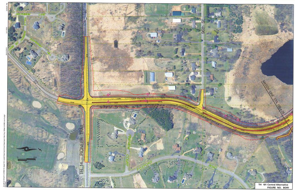
13 List of Figures Figure 1 TH 101 Central Alternative, BOR 1 Figure 2 TH 101 Central Alternative, BOR 2


14 S:\AE\C\Chanh\114382\5-dsgn\51-cadd\Geotechnical\Geotech-Boring DGNs\114382_borA.dgn 3/11/2011 8:58:58 AM Default shotchkin HALLA NURSERY DR. WEST DELPHINIUM LANE RASPBERRY HILL feet TH 14 - PIONEER TRAIL PINEVIEW COURT 4 3 FOXFORD 96th St ROAD MATCH LINE STA LEGEND - Preliminary Design Phase Boring (Complete) - Recommended Additional Boring TH 101 Central Alternative FIGURE NO. BOR1 10


15 3/11/2011 9:01:02 AM 0 feet 200 S:\AE\C\Chanh\114382\5-dsgn\51-cadd\Geotechnical\Geotech-Boring DGNs\114382_borB.dgn Default shotchkin S. T Kiowa Trail MATCH LINE STA TH T 94 WES KIO W A T R A I BANDIMERE PARK Preliminary Design Phase Boring (Complete) Recommended Additional Boring R E E NV E W SUM MERFIEL D D RIVE OVERLOOK CT. LYMAN BLVD. BOUL LYMAN TH 101 Central Alternative FIGURE NO.BOR2
16 Appendix A Braun Intertec Report Results of Soil Borings and Laboratory Testing
17
18
19
20
21

22
23
24 State Project Ground Elevation TH 101 Reconstruction ST Location DEPTH MINNESOTA DEPARTMENT OF TRANSPORTATION - GEOTECHNICAL SECTION Bridge No. or Job Desc. Trunk Highway/Location Carver Co. Coordinate: X= Y= Latitude (North)= Depth Elev. LABORATORY LOG & TEST RESULTS - SUBSURFACE EXPLORATION Lithology UNIQUE NUMBER U.S. Customary Units Longitude (West)= Classification (ft.) Boring No. (Surveyed) Drill Machine 7504 SHEET 1 of 1 Drilling Hammer CME Automatic Calibrated Completed 1/26/11 Drilling Operation SPT N60 REC MC (%) RQD COH (psf) ACL (%) (%) (ft) (pcf) Core Breaks Soil Rock Other Tests Or Remarks Formation or Member CLAY, black, wet. (Topsoil) CLAY, with trace Fibers, brown with trace black, wet, firm. (Alluvium) SILT LOAM, light brown, moist to saturated, loose. (Glaciofluvium) SANDY LOAM, plastic, with trace Gravel, brown, wet, stiff. (Glacial Till) CLAY, with trace Gravel, brown, wet, firm. (Glacial Till) Bottom of Hole - 11 feet. Water observed at 5 1/2 feet while drilling. Water at 7 feet with cave-in depth of 8 feet immediately after withdrawal of auger. Boring immediately backfilled qu=1 tsf qu=2 tsf Index Sheet Code 3.0 Soil Class:J. Van Abel Rock Class: Edit: Date: 3/10/11 N:\GINT\PROJECTS\MINNEAPOLIS\2010\09340-MNDOT.GPJ
25
26
27
28
29
30
31
32
33 State Project Bridge No. or Job Desc. Trunk Highway/Location 6 1/2 inches of Bituminous. 6 1/2 inches of Aggregate Base. CLAY, dark brown, wet. (Fill) CLAY, trace Gravel, with Loamy Sand seams, gray and brown, wet, firm (Glacial Till) CLAY, trace Gravel, brown, moist to wet, stiff to very stiff. (Glacial Till) Boring No. Ground Elevation TH 101 Reconstruction ST Location DEPTH 5 10 MINNESOTA DEPARTMENT OF TRANSPORTATION - GEOTECHNICAL SECTION Carver Co. Coordinate: X= Y= Latitude (North)= Depth Elev. LABORATORY LOG & TEST RESULTS - SUBSURFACE EXPLORATION Lithology UNIQUE NUMBER U.S. Customary Units Longitude (West)= Classification (ft.) (Surveyed) Drill Machine 7514 SHEET 1 of 1 Drilling Hammer CME Automatic Calibrated Completed 12/30/10 Drilling Operation SPT N60 REC MC (%) RQD COH (psf) ACL (%) (%) (ft) (pcf) Core Breaks Soil Rock Other Tests Or Remarks qu=1 1/2 tsf qu=4+ tsf Formation or Member qu=3 1/2 tsf 15 CLAY, trace Gravel, gray, wet, very stiff to hard. (Glacial Till) 22 qu=3 1/2 tsf Bottom of Hole - 21 feet. Water not observed with 19 1/2 feet of hollow-stem auger in the ground. Water not observed to cave-in depth of 17 feet immediately after withdrawal of auger. Boring immediately backfilled. 23 Index Sheet Code 3.0 Soil Class:J. Van Abel Rock Class: Edit: Date: 3/10/11 N:\GINT\PROJECTS\MINNEAPOLIS\2010\09340-MNDOT.GPJ
34 State Project Ground Elevation TH 101 Reconstruction ST Location DEPTH MINNESOTA DEPARTMENT OF TRANSPORTATION - GEOTECHNICAL SECTION Bridge No. or Job Desc. Trunk Highway/Location Carver Co. Coordinate: X= Y= Latitude (North)= Depth Elev. LABORATORY LOG & TEST RESULTS - SUBSURFACE EXPLORATION Lithology UNIQUE NUMBER U.S. Customary Units Longitude (West)= Classification (ft.) Boring No. (Surveyed) Drill Machine 7504 SHEET 1 of 1 Drilling Hammer CME Automatic Calibrated Completed 1/4/11 Drilling Operation SPT N60 REC MC (%) RQD COH (psf) ACL (%) (%) (ft) (pcf) Core Breaks Soil Rock Other Tests Or Remarks Formation or Member SILT LOAM, organic, black, wet. (Topsoil) CLAY LOAM, trace Gravel, brown and light gray, wet, soft. (Alluvium) qu<1/4 tsf qu=1 1/2 tsf qu=2 tsf qu=2 tsf CLAY, trace Gravel, brown to gray, wet, stiff to very stiff. (Glacial Till) 13 qu=2 1/2 tsf qu=2 1/2 tsf Bottom of Hole - 21 feet. Water observed at 3 feet with 2 feet of hollow-stem auger in the ground. Water not observed immediately after withdrawal of auger. Boring immediately backfilled with bentonite grout. 25 Index Sheet Code 3.0 Soil Class:J. Van Abel Rock Class: Edit: Date: 3/10/11 N:\GINT\PROJECTS\MINNEAPOLIS\2010\09340-MNDOT.GPJ
35 State Project Ground Elevation TH 101 Reconstruction ST Location DEPTH MINNESOTA DEPARTMENT OF TRANSPORTATION - GEOTECHNICAL SECTION Bridge No. or Job Desc. Trunk Highway/Location Carver Co. Coordinate: X= Y= Latitude (North)= Depth Elev. LABORATORY LOG & TEST RESULTS - SUBSURFACE EXPLORATION Lithology UNIQUE NUMBER U.S. Customary Units Longitude (West)= Classification (ft.) Boring No. (Surveyed) Drill Machine 7504 SHEET 1 of 1 Drilling Hammer CME Automatic Calibrated Completed 1/4/11 Drilling Operation SPT N60 REC MC (%) RQD COH (psf) ACL (%) (%) (ft) (pcf) Core Breaks Soil Rock Other Tests Or Remarks Formation or Member CLAY, with occasional Loamy Sand seams, trace fibers, slightly organic to organic, black to brown, wet, soft. (Alluvium/Topsoil) SANDY LOAM, slightly plastic, gray, saturated, very loose. (Alluvium) 2* *Limited sample recovery. qu<1/2 tsf 15 CLAY, with frequent seams and layers of Sand and Loamy Sand, trace Gravel, gray, wet, soft. (Glaciofluvium/Alluvium) qu=1 tsf 25 CLAY, with occasional Loamy Sand seams, gray, wet, firm. (Glacial Till) 5 26 qu=1 1/4 tsf CLAY, trace Gravel, gray, wet, stiff. (Glacial Till) Bottom of Hole - 31 feet. Water observed at 4 feet with 4 1/2 feet of hollow-stem auger in the ground. Water observed at 3 feet with a cave-in depth of 4 feet immediately after withdrawal of auger. Boring immediately backfilled with bentonite grout. 13 qu=2 tsf Index Sheet Code 3.0 Soil Class:J. Van Abel Rock Class: Edit: Date: 3/10/11 N:\GINT\PROJECTS\MINNEAPOLIS\2010\09340-MNDOT.GPJ
36 State Project Bridge No. or Job Desc. 7 inches of Bituminous. 6 inches of Aggregate Base. Trunk Highway/Location SANDY LOAM, non plastic, brown and dark brown, moist. (Fill) Bottom of Hole - 6 feet. Water not observed with 4 1/2 feet of hollow-stem auger in the ground. Water not observed to cave-in depth of 3 1/2 feet immediately after withdrawal of auger. Boring immediately backfilled Boring No. Ground Elevation TH 101 Reconstruction ST Location DEPTH 5 MINNESOTA DEPARTMENT OF TRANSPORTATION - GEOTECHNICAL SECTION Carver Co. Coordinate: X= Y= Latitude (North)= Depth Elev. LABORATORY LOG & TEST RESULTS - SUBSURFACE EXPLORATION Lithology UNIQUE NUMBER U.S. Customary Units Longitude (West)= Classification (ft.) (Surveyed) Drill Machine 7514 SHEET 1 of 1 Drilling Hammer CME Automatic Calibrated Completed 12/30/10 Drilling Operation SPT N60 REC MC (%) RQD COH (psf) ACL (%) (%) (ft) (pcf) Core Breaks Soil Rock Other Tests Or Remarks Formation or Member Index Sheet Code 3.0 Soil Class:J. Van Abel Rock Class: Edit: Date: 3/10/11 N:\GINT\PROJECTS\MINNEAPOLIS\2010\09340-MNDOT.GPJ
37
38
39 State Project CLAY, slightly organic to organic, trace fibers, dark brown, frozen to wet. (Topsoil/Alluvium) CLAY, organic, with Sand seams, trace fibers, black, wet, very soft to soft. (Alluvium) CLAY LOAM, trace fibers and Gravel, brown, wet, soft to firm. (Alluvium) Boring No. Ground Elevation TH 101 Reconstruction ST Location DEPTH 5 10 MINNESOTA DEPARTMENT OF TRANSPORTATION - GEOTECHNICAL SECTION Bridge No. or Job Desc. Trunk Highway/Location Carver Co. Coordinate: X= Y= Latitude (North)= Depth Elev. LABORATORY LOG & TEST RESULTS - SUBSURFACE EXPLORATION Lithology UNIQUE NUMBER U.S. Customary Units Longitude (West)= Classification (ft.) (Surveyed) Drill Machine 7504 SHEET 1 of 1 Drilling Hammer CME Automatic Calibrated Completed 1/4/11 Drilling Operation SPT N60 REC MC (%) RQD COH (psf) ACL (%) (%) (ft) (pcf) Core Breaks Soil Rock qu<1/4 tsf qu=1/2 tsf Other Tests Or Remarks Formation or Member 15 LOAMY SAND, fine to coarse grained, with Gravel, brown to gray, saturated, medium dense to loose. (Glacial Outwash) qu=1 1/2 tsf 25 CLAY, trace Gravel, gray, wet, firm to stiff. (Glacial Till) 11 qu=2 tsf Bottom of Hole - 31 feet. Water observed at 3 feet with 2 feet of hollow-stem auger in the ground. Water observed at 2 feet with a cave-in depth of 4 feet immediately after withdrawal of auger. Boring immediately backfilled with bentonite grout. 13 qu=2 tsf Index Sheet Code 3.0 Soil Class:J. Van Abel Rock Class: Edit: Date: 3/10/11 N:\GINT\PROJECTS\MINNEAPOLIS\2010\09340-MNDOT.GPJ
40
41 State Project Bridge No. or Job Desc. 5 inches Bituminous. Trunk Highway/Location LOAMY SAND, fine to coarse grained, with a trace to a little Gravel, dark brown and brown, moist. (Fill) CLAY, with trace Gravel, with Sandy Loam seams, brown, dark brown and gray, wet. (Fill) SANDY LOAM, with trace Gravel, brown and gray, moist to saturated, loose. (Alluvium) CLAY, with trace Gravel and fibers, dark brown to gray, wet, firm. (Alluvium) 6 24 qu=1/2 tsf Bottom of Hole - 11 feet. Water observed at 7 feet with 9 1/2 feet of hollow-stem auger in the ground. Water not observed to cave-in depth of 7 feet immediately after withdrawal of auger. Boring immediately backfilled Boring No. Ground Elevation TH 101 Reconstruction ST Location DEPTH 5 MINNESOTA DEPARTMENT OF TRANSPORTATION - GEOTECHNICAL SECTION Carver Co. Coordinate: X= Y= Latitude (North)= Depth Elev. LABORATORY LOG & TEST RESULTS - SUBSURFACE EXPLORATION Lithology UNIQUE NUMBER U.S. Customary Units Longitude (West)= Classification (ft.) (Surveyed) Drill Machine 7514 SHEET 1 of 1 Drilling Hammer CME Automatic Calibrated Completed 1/7/11 Drilling Operation SPT N60 REC MC (%) RQD COH (psf) ACL (%) (%) (ft) (pcf) Core Breaks Soil Rock Other Tests Or Remarks Formation or Member Index Sheet Code 3.0 Soil Class:J. Van Abel Rock Class: Edit: Date: 3/10/11 N:\GINT\PROJECTS\MINNEAPOLIS\2010\09340-MNDOT.GPJ
42
43
44
45
46
47
48