Machine guarding without limitations. Workspace Creation. Tel: Unit B1 Astra Park Parkside Lane Leeds West Yorkshire LS11 5SZ
|
|
|
- Marjorie McBride
- 5 years ago
- Views:
Transcription

1 Machine guarding without limitations Workspace Creation Tel: Web: Unit B1 Astra Park Parkside Lane Leeds West Yorkshire LS11 5SZ 1


2 2 a completely NEW way of thinking for machine guarding


3 3


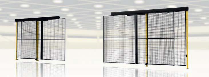
4 a FLEXIBLE system with extremely SMART solutions X-Guard has a unique and extremely smart design that is quick to assemble, easy to renew, change and supplement to suit different applications. We have put safety and functionality in focus when producing the new system in order to ensure the best possible machine guard. Quite simply, it is the only machine guard you need. Free selection. Switch when it suits you. Doors and panels are designed to ensure you can switch whenever necessary. You can change hinge and lock handing with a simple operation. This means you can quickly change the machine guard as and when the need arises. Free height adjustment Option for mm vertical adjustment of the panels. The height of doors can also be adjusted. You are free to adjust entirely in line with your requirements. Foot cover The cover gives a more refined finish while being easier to keep clean. 4


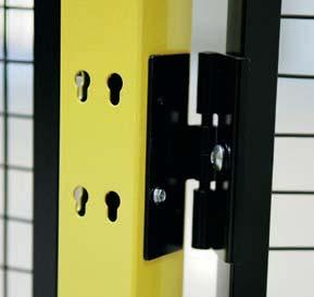
5 X-Key A unique key designed for the rapid release of a panel. One function is for removing the panel from the outside, when the key is rotated in its handle it can be used for removing panels from the inside. Forget all other tools. The X-Key is all you need. Upper panel bracket with snap on function Upper bracket means that the panels can be easily attached and removed from both inside and outside an enclosure. You can also put a safety lock on the bracket to prevent removal of a panel from the outside. The bracket can be applied to a post on three different sides (at a fixed height). Lower panel bracket The lower bracket guides the panel into the correct position when assembling. Two guides mean the panel falls easily into place. 5


6 DOORS, LOCKS and ACCESSORIES


7 Upper bracket Simple snap on brackets can be fitted to three sides of a post. 02. Lower bracket Guides the panel into the correct position when assembling. 03. Hinge You can easily replace a wall bracket with a hinge, even after installation. 04. Top plug Used for mounting of tubular door lintel, cable conduit etc. 05. Tubular frame Width adjusted during assembly to suit door opening. 06. Cutting package Available for vertical and horizontal cutting. 07. Single sliding door Single opening for pedestrian access. 08. Bi-parting sliding door Operates on a double rail with individual locking options for each door. 09. Single hinge door For pedestrian access or emergency exit. 10. Double hinge door Access for wider goods, pallet truck etc. 11. Single sliding door without rail Ideal for fork lift truck or even larger vehicle access. 12. Double sliding door without rail With a six metres wide opening. 13. Rail for sliding door New design steel sliding door rail. 14. X-Lock Axelent s own safety lock that cannot be closed from the inside, but can always be opened. 15. Cylinder lock Burglar proof locking system with easy grip handle fittings Fittings for creating corners up to Snap lock The door is closed with a simple press and kept closed via the snap function. 18. X-Key Tool for releasing a panel. 7

8 This text and diagram are published with kind permission from SIS Förlag AB Stockholm, Sweden, , who also sells the standards that are referred to in the text. SAFETY OF MACHINERY STANDARDS AND RISK ASSESSMENT What are the reasons for us continuously working to improve machine safety within the industry? The first and most important reason is moral: each employee is entitled to a safe and secure working environment. The next reason is financial, as workplace accidents involve huge costs due to sick leave, compensation and production downtime. The final reason is to fulfil legal requirements: where we were previously governed by national regulations, but today are governed by different EU directives. Axelent AB and Axelent Safety AB are specialists within these fields and offer complete solutions from risk analysis to delivery and assembly of machine guard. Axelent manufactures and sells mesh wall systems for machine constructors, warehouse fitters and construction contractors. Axelent Safety offers complete solutions within machine safety, from design to safe and approved machinery, including advice and training. Figure A.1 (EN ISO 13857) Case 1 Case 2 Case 3 From 29 December 2009, a new Machinery Directive 2006/42/EC will apply. Some of the changes in brief include: have also been raised, e.g. a documented risk analysis must be carried out. and the technical requirements have been expanded and clarified to a certain extent, e.g. ergonomic and control system requirements have been made more precise. IV machinery. For more information, see newapproach/standardization/harmstds/reflist.html 1. Fixed guards Fixed guards must be fixed by systems that can be opened or removed only with tools. Their fixing systems must remain attached to the guards or to the machinery when the guards are removed. (Valid from 29/12/2009.) Where possible, guards must be incapable of remaining in place without their fixings. 2. Safety Distances EN 953 chapter Guards intended for preventing access to danger zones shall be designed, constructed and positioned to prevent parts of the body from reaching danger zones (see also EN ISO 13857). a - Reference plane b - Hip joint c - Protective structure Table A.1 (EN ISO 13857) Height up to protective structure (h) h - Height up to protective structure l - Distance for impedance Distance (l) Case 1 Case 2 Case 3 h < h < h < h < h Dimensions in mm Figure A.1 Impeding free movement under protective structures. Table A.1 gives distances for particular cases where access of the lower limbs is impeded when the person remains in a standing position (see figure A.1) without any additional support. Where there is a risk of slipping or misuse, applying the values given in Table A.1 can be inappropriate. There should be no interpolation between the values in this table. If the height, h, up to the protective structure lies between two values, then the distance for the higher value of h should be used (for further information see EN ISO chapter 4.3) Distances to impede free access EN ISO A protective structure can be used to restrict the free movement of the lower limbs under protective structures. When this method has to be used, distances are given in annex A in relation to the height to the protective structure.
9 4. Regular openings for persons of 14 years of age and above EN ISO chapter which gives a safety distance of 120 mm, Axelent s other machine guard systems has an aperture of 29 x 49 mm which gives a safety distance of 200 mm (for further information see EN ISO chapter table 4). 5. Viewing EN 953 chapter To minimise the need to remove them, guards shall be designed and constructed to offer adequate viewing of the process. EN 953 chapter 5.10 Where viewing of machine operation is required through the guard, materials shall be selected with suitable properties, e.g. if perforate material or wire mesh is used this should be of adequate open area and suitable colour to permit viewing. Viewing will be enhanced if the perforate material is darker than the area observed. 6. Transparency EN 953 chapter 5.11 As far as practicable, materials used for viewing machine operation shall be selected from those which retain their transparency, with age and use. Guards shall be designed to make provision for the replacement of degraded materials. Certain applications can require the selection of materials or combinations of materials that are resistant to abrasion, chemical attack, degradation by ultra violet radiation, dust attraction by static electrical charge, or surface wetting by fluids which impair transparency. 7. Colour EN 953 chapter 7.5 Hazards can be highlighted by the use of suitable colours. For example if a guard is painted the same colour as the machine and the hazardous parts painted a contrasting bright colour, attention is drawn to the hazard when the guard is opened or left off. 8. Positive location of removable guards EN 953 chapter Where practicable removable guards shall be unable to remain in place without their fixings. 9. Removal only by tool EN 953 chapter Demountable parts of guards shall only be removable with the aid of a tool. VALUES FOR SAFETY DISTANCES EN ISO chapter table 2 Dimensions in mm Height of hazard zone c a Height of protective structure a, b b Horizontal safety distance to hazard zone, c a b Protective structures less than 1000 mm in height are not included because they do not sufficiently restrict movement of the body. Protective structures lower than 1400 mm should not be used without additional safety measures. c For hazard zones above 2700 mm, refer to


10 AFETY OF MACHINERY STANDARDS AND RISK ASSESSMENT Important notice: 10. Geometrical factors EN ISO chapter The design of the machine shall be such that, from the main control position, the operator is able to ensure that there are no exposed persons in the danger zones. 11. Measures for the escape and rescue of trapped persons EN ISO chapter may consist, e.g. of: operator-trapping hazards; after an emergency stop; elements; to call for help. As this is a sample from the applicable standards, we recommend that you read the standard relevant to each application. This document is subject to changes in applicable directives and standards. 10