COPYRIGHT MATERIALS. Wind Solutions - Perforated Wood Structural Panel Shear Walls (DES 416)
|
|
|
- Philippa Montgomery
- 5 years ago
- Views:
Transcription

1 Wind Solutions - Perforated Wood Structural Panel Shear Walls (DES 416) Lori Koch, M.S., M.F., P.E. Manager, Educational Outreach American Wood Council Adam Robertson, M.A.Sc., P.Eng. Manager, Codes and Standards Canadian Wood Council COPYRIGHT MATERIALS This presentation is protected by US and International Copyright laws. Reproduction, distribution, display and use of the presentation without written permission is prohibited. American Wood Council
2 DESCRIPTION AWC s 2015 Special Design Provisions for Wind and Seismic (SDPWS), 2015 Wood Frame Construction Manual (WFCM), and 2015 WFCM High Wind Guides contain provisions for the design of perforated wood structural panel shear walls. This presentation will provide examples of perforated shear wall design utilizing the WFCM, High Wind Guides, SDPWS, and the WoodWorks software using both prescriptive and engineered solutions within the WFCM and SDPWS. 3 LEARNING OBJECTIVES At the end of this program, participants will be better able to: 1. Evaluate a prescriptive and engineered design methodology for perforated wood shear walls. 2. Understand how to design wood structural panels to resist wind loads. 3. Design a wood frame wood structural panel shear wall shear loads. 4. Acquire knowledge on resources to develop solutions for resisting wind loads. 4 2
3 POLLING QUESTION 1. What is your profession? a) Architect b) Engineer c) Building Code Official d) Fire Service e) Other 5 OUTLINE 2015 IBC/IRC Recognition Background and Assumptions Design Examples 2015 WFCM Prescriptive 2015 WFCM Engineered 2015 SDPWS 2015 WFCM High Wind Guides 6 3


4 WFCM AND IRC/IBC 2015 WFCM is referenced in 2015 IRC/IBC 7 APPLICABILITY LIMITS Wood Shear Wall Seismic and Wind Design 8 4
5 2015 WFCM NON-RESIDENTIAL Applications Single-story Slab-on-grade L and W < 80 Examples Commercial/Retail Restaurants Office Buildings Design Lateral (Wind and Seismic) Gravity WFCM Wood Shear Wall Seismic and Wind Design WFCM p. v 10 5


6 2015 WFCM 2015 WFCM uses SDPWS for shear capacities and ASCE 7-10 provisions for loads Wood Shear Wall Seismic and Wind Design 11 SDPWS AND IBC 2015 SDPWS is referenced in 2015 IBC Wood Shear Wall Seismic and Wind Design 12 6
 segmented shear wall b) perforated shear wall c) force transfer")
7 SDPWS 2015 SDPWS Engineered Res and Non-Res ASD & LRFD Shear wall provisions Segmented Perforated Force Transfer Around Openings 13 POLLING QUESTION 2.The Special Design Provisions for Wind and Seismic standard includes which of the following that is not included in the WFCM: a) segmented shear wall b) perforated shear wall c) force transfer around openings shear wall d) Hold downs 14 7
8 OUTLINE 2015 IBC/IRC Recognition Background and Assumptions Design Examples 2015 WFCM Prescriptive 2015 WFCM Engineered 2015 SDPWS 2015 WFCM High Wind Guides 15 SEGMENTED SHEAR WALL (SSW) METHOD Lots of hold-downs Wall need not be fully sheathed 16 8
9 PERFORATED SHEAR WALL (PSW) METHOD Only ends Wall must be fully sheathed 17 WFCM PRESCRIPTIVE Wind Speeds mph Exp. B & C Segmented & Perforated Shear Walls Other Application Limits 18 9


10 WFCM PRESCRIPTIVE 19 WFCM PRESCRIPTIVE SDPWS Shear Distribution 20 10
11 POLLING QUESTION 3.The minimum shear walls construction consists of: a) 3/8 wood structural panels on wall exterior b) 8d common 6 oc at panel edges c) 8d common 10 oc in panel field d) All of the above e) a) and b) only 21 OUTLINE 2015 IBC/IRC Recognition Background and Assumptions Design Examples 2015 WFCM Prescriptive 2015 WFCM Engineered 2015 SDPWS 2015 WFCM High Wind Guides 22 11


12 DESIGN EXAMPLE Design first floor shear wall 23 DESIGN EXAMPLE 24 12


13 DESIGN EXAMPLE 25 WFCM PRESCRIPTIVE 2015 WFCM Prescriptive Segmented Shear Wall 26 13

14 WFCM PRESCRIPTIVE 2015 WFCM Prescriptive Segmented Interpolate = WFCM PRESCRIPTIVE 28 14
 = 19.3' w/ blocked gypsum 12.5 / 40' = 31% 12.5'(1.70) = 21.2' w/o gypsum 22' Full-height sheathing > 21.2 OK Note: Max. aspect ratio = 3.")
15 WFCM PRESCRIPTIVE 29 WFCM PRESCRIPTIVE 2015 WFCM Prescriptive Perforated Shear Wall % Full-height sheathing 10.9 / 40' = 27% Interpolated = (1.78) = 19.3' w/ blocked gypsum 12.5 / 40' = 31% 12.5'(1.70) = 21.2' w/o gypsum 22' Full-height sheathing > 21.2 OK Note: Max. aspect ratio = 3.5:1 for PSW segments 30 15

16 WFCM PRESCRIPTIVE 2015 WFCM Prescriptive Hold-downs Hold-downs 3,924 / 0.60 = 6,540 lbs w/ blocked gypsum 3,924 / 0.69 = 5,687 lbs w/o gypsum Need to combine with top floor hold-down requirements Based on capacity of first shear wall panel Does not include dead load 31 WFCM ENGINEERED 2015 WFCM Engineered w roof = 169 plf w floor = 194(0.91)*=177 plf w total = 346 plf 346 (32')/2 = 5,536 lbs Roof A trib = gable + ½ wall Floor A trib = ½ wall + ½ wall *Footnote 2: (H+1)/11 adjustment = (9+1)/


17 WFCM ENGINEERED 2015 WFCM Engineered Segmented 2 Walls having aspect ratios exceeding 1.5:1 shall be blocked shear walls and the maximum aspect ratio shall not exceed 2:1 in accordance with SDPWS Table WFCM ENGINEERED 2015 WFCM Engineered Segmented Required Capacity = 5,536 lbs 7/16 WSP Capacity = 630 plf 1/2 Gypsum Capacity = 100 plf Total = 730 plf 5,536/730 = 7.6' (w/ blocked gypsum) 5,536/630 = 8.7' (w/o gypsum) 34 17
*3 )] = 18 L tot = 40 %FHS = 18 / 40 = 45% Interpolated C o Factor = 0.55 730(0.55) = 402 plf 5,536/402 = 13.8 < 18 (w/ blocked gypsum) 630(0.")
18 WFCM ENGINEERED 2015 WFCM Engineered - Perforated Reference SDPWS Capacities and Adjustments V = 5,536 lbs v = 730 plf (w/ blocked gypsum) v = 630 plf (w/o gypsum) %FHS = L i / L tot L i = 2(5 ) + 4[(2*3 /9 )*3 )] = 18 L tot = 40 %FHS = 18 / 40 = 45% Interpolated C o Factor = (0.55) = 402 plf 5,536/402 = 13.8 < 18 (w/ blocked gypsum) 630(0.55) = 347 plf 5,536/347 = 16 < 18 (w/o gypsum) Note: L i per SDPWS adjustment = 2b s /h 35 WFCM ENGINEERED 2015 WFCM Engineered Hold-downs T = v h v = 730 plf (w/ blocked gypsum) v = 630 plf (w/o gypsum) h = 9 T = 730(9 ) = 6,570 lbs T = 630(9 ) = 5,670 lbs Need to combine with top floor hold-down requirements Based on capacity of first shear wall panel Can account for dead load (WFCM 2.2.4) 36 18

19 2015 SDPWS WSP CAPACITY ASD Capacity = 1065/2 = 533 plf SDPWS WSP CAPACITY ASD Capacity = 200/2 = 100 plf 38 19
20 SDPWS 2015 SDPWS Perforated Shear Wall Shear Capacity Adjustment Factor (SDPWS Eqns & 4.3-6) h = 9 L i = 2(5)+ 4[(2*3/9)*3] = 18 L tot = 40 A o = 4(4.5 )(3 ) + (6 )(7.5 ) = 99 ft 2 r = 0.62 C o = 0.78 (based on total sheathed area) Note: L i per SDPWS adjustment = 2b s /h 39 SDPWS 2015 SDPWS Perforated Shear Wall C o = 0.78 w/ blocked gypsum 633 (0.78) = 494 5,536/494 = 11.2' w/o gypsum 533 (0.78) = 416 5,536/416 = ' Effective Full-height sheathing > 13.3' OK 40 20
21 SDPWS 2015 SDPWS Perforated Shear Wall 5,536lbs 18' Effective Full-height sheathing > 13.3' OK 41 SDPWS 2015 SDPWS Hold-downs (Perforated) V = 5,536 lbs h = 9' C o = 0.78 L i = 18' T = 3,549 lbs Req d Hold-down Capacity = 3,549 lbs In the design of perforated shear walls, the length of each perforated shear wall segment with an aspect ratio greater than 2:1 shall be multiplied by 2b s /h for the purposes of determining L i and L i Need to combine with top floor hold-down requirements Based on loads Can account for dead load ( ) 42 21
![WIND DESIGN EXAMPLE - SUMMARY 2015 WFCM/SDPWS Shear Wall Length Comparison [Bracketed text indicates values without gypsum] AWC Standard](/docs-images/90/103085623/images/22-0.jpg "2015 WFCM Prescriptive 2015 WFCM Engineered Full Height Sheathing Hold-downs, lbs 19.3 [21.2 ] (3/12) 6,540 [5,687] 13.")
![8 [16 ] (3/12) 6,570 [5,670] 2015 SDPWS 11.2 [13.](/docs-images/90/103085623/images/22-1.jpg "3 ] (4/12) 3,549 [PSW] 43 WOODWORKS DESIGN OFFICE 11 SOFTWARE SIZER Gravity Design Concept mode Beam mode Column mode SHEARWALLS Lateral")
22 WIND DESIGN EXAMPLE - SUMMARY 2015 WFCM/SDPWS Shear Wall Length Comparison [Bracketed text indicates values without gypsum] AWC Standard 2015 WFCM Prescriptive 2015 WFCM Engineered Full Height Sheathing Hold-downs, lbs 19.3 [21.2 ] (3/12) 6,540 [5,687] 13.8 [16 ] (3/12) 6,570 [5,670] 2015 SDPWS 11.2 [13.3 ] (4/12) 3,549 [PSW] 43 WOODWORKS DESIGN OFFICE 11 SOFTWARE SIZER Gravity Design Concept mode Beam mode Column mode SHEARWALLS Lateral Design (Wind and Seismic) CONNECTIONS Fasteners DATABASE EDITOR Add proprietary products woodworks-software.com 44 22
 for each level from CAD & import each level 3.")

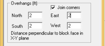
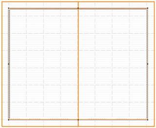
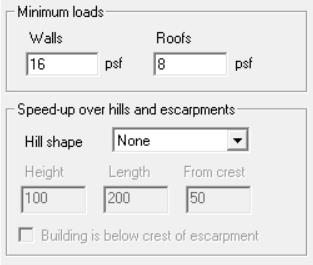
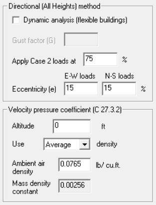
23 WOODWORKS CAD IMPORT 1. Specify # of levels 2. Export metafile (.pdf,.emf,.wmf,.bmp) for each level from CAD & import each level 3. Select Start positioning 4. Use Zoom controls to place crosshairs on CAD drawing 5. Input (x,y) coordinates & distances 45 WOODWORKS DESIGN SETTINGS 46 23

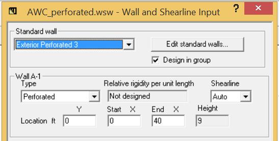
24 WOODWORKS 47 WOODWORKS 48 24

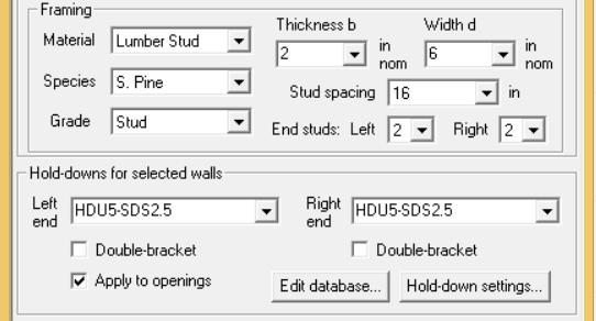
25 WOODWORKS 49 WOODWORKS 50 25

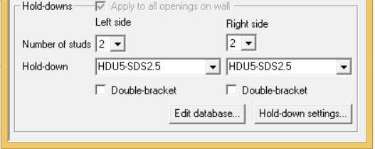
26 WOODWORKS 51 WOODWORKS 52 26

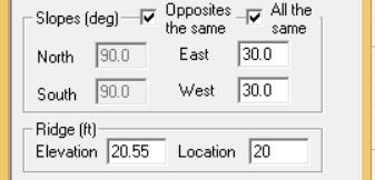
27 WOODWORKS 53 WOODWORKS 54 27

28 WOODWORKS 55 WOODWORKS 56 28

29 WOODWORKS 57 WOODWORKS 58 29

30 WOODWORKS 59 WOODWORKS 60 30
31 WOODWORKS 61 WOODWORKS 62 31

32 WOODWORKS 63 WOODWORKS 64 32

33 WOODWORKS 65 WOODWORKS 66 33

34 WOODWORKS 67 WOODWORKS 68 34

35 WOODWORKS 69 WOODWORKS 70 35

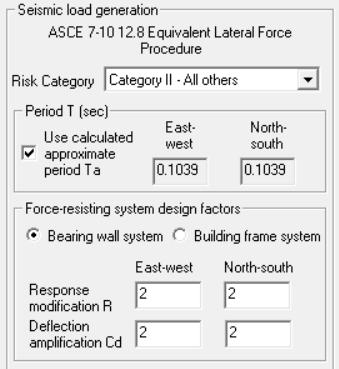
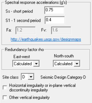
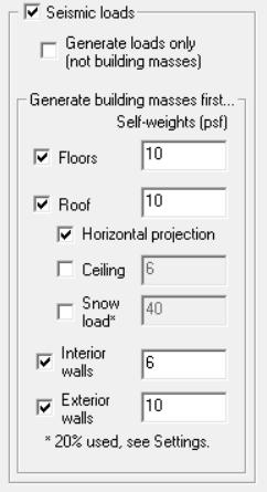
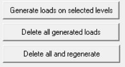
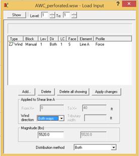
36 POLLING QUESTION 4.The WoodWorks Shearwalls software has the ability to automatically generate wind and seismic loads, as well as the ability to manually input lateral loads? a) True b) False WFCM HIGH WIND GUIDES 72 36
 = 80 73 2015 WFCM HIGH WIND GUIDES Additional restrictions beyond WFCM")

37 2015 WFCM HIGH WIND GUIDES Scope restrictions Mean Roof Height (MRH) maximum = 33 Top plate to ridge height maximum = 10 Roof truss/rafter maximum span = 36 Maximum building dimension (L or W) = WFCM HIGH WIND GUIDES Additional restrictions beyond WFCM Openings limited to 6-8 Can go up to 8 with 5% increase in FHS lengths (Tables 12/13) Aspect Ratios are limited based on wind speed Buildings must be rectangular (max. 4 wall offset) Non-rectangular buildings can use inscribed method Separate structures must be designed per WFCM 74 37

38 DESIGN EXAMPLE Assumptions 140 mph (700-yr, 3-second gust) Exposure B L=36 W=30 5/12 roof pitch Top plate to ridge = story 8 wall height 6 8 door height 4 window height Wood Structural Panel Exterior Sheathing w/ Gable End Walls 75 DESIGN EXAMPLE L/W = 36 /30 =

39 DESIGN EXAMPLE Wall Heights = 8 OK 77 DESIGN EXAMPLE 78 39
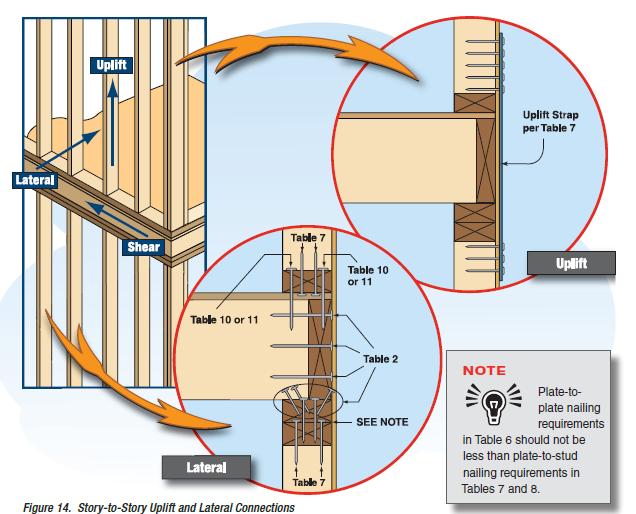
40 WFCM HIGH WIND GUIDE Assumes perforated shear wall with hold-downs only at the ends 79 WFCM HIGH WIND GUIDE Load Bearing Walls Second Floor Using 6 edge/ 12 field spacing: L/W = 36'/30' = 1.2 Interpolated = 36.2% = 13' Available = 23.5' OK Hold Down Capacity = 4,360 lb 80 40

41 WFCM HIGH WIND GUIDE Load Bearing Walls First Floor Using 6 edge/ 12 field spacing: L/W = 36'/30' = 1.2 Interpolated = 59.8% = 21.5' Available = 21' NG! Using 4 edge/ 12 field spacing: L/W = 36'/30' = 1.2 Interpolated = 46.8% = 16.9' Available = 21' OK Hold Down Capacity = 5,900 lb Combined Hold-down 5, ,360 = 10,260 lb 81 WFCM HIGH WIND GUIDE Gable End Second Floor Using 6 edge/ 12 field spacing: L/W = 36'/30' = 1.2 Interpolated = 47.4% = 14.2 Maximum Openings = 15.8 Hold Down Capacity = 4,360 lb Gable End First Floor Using 6 edge/ 12 field spacing: L/W = 36'/30' = 1.2 Interpolated = 75% = 22.5 Maximum Openings = 7.5 Hold Down Capacity = 4,360 lb Combined Hold-down 4, ,360 = 8,720 lb 82 41
 2015 International Building Code b) 2015 SDPWS c) ASCE 7 10 d)")
42 WFCM HIGH WIND GUIDE Controlling Hold Down 10,260 lb > 8,720 lb 10,260 lb can be used at all 4 corners 83 POLLING QUESTION 5. The 2015 WFCM uses shear wall design capacities from which of the following: a) 2015 International Building Code b) 2015 SDPWS c) ASCE 7 10 d) None of the above 84 42
43 This concludes the American Institute of Architects Continuing Education Systems Course This presentation is protected by US and International Copyright laws. Reproduction, distribution, display and use of the presentation without written permission of American Wood Council (AWC) is prohibited. American Wood Council 2018 WOODWORKS DESIGN OFFICE 11 SOFTWARE SIZER Gravity Design Concept mode Beam mode Column mode DATABASE EDITOR Add proprietary products 10% discount for AWC members Promo code: awc SHEARWALLS Lateral Design (Wind and Seismic) For more information contact: CONNECTIONS Fasteners or 86 43