Zacq Consultants. An Overview
|
|
|
- Clare Sullivan
- 5 years ago
- Views:
Transcription
1 Zacq Consultants An Overview
2 Introduction Zacq Consultants is a company, located in the city Pune of India. Zacq Consultants offer Computer Aided Engineering (CAE) Services/Solutions for Automotive/Aerospace/Energy/Nonautomative /Heavy engineering Domestic and Overseas Customers using FEA and CFD techniques. Backed by experience in Engineering outsourcing processes and project management systems, Zacq Consultants easily gets integrated with customers and customers enjoy the most effective seamless association with us.
3 Vision In long term, Zacq Consultants aim to be recognized as a reliable research oriented Domain Expert, working hand in hand with customers at every stage of product development from concept to production stage. In order to achieve this goal, we are working on venturing in Design with Finite element analysis ONE STOP Solution for customer. Our focus is to develop long term association with leading companies by consistently adding value to customer s product.
4 Services Engineering Services - Mechanical integrity (start to end) - Design validation calculations by using FEA/CAE/Hand calculations for current designs or new designs - Connection simulations (like welds, bolts and similar) - Design optimization solution (weight, functions and similar) - Structural stress analysis - Finite element Analysis (FEA) / CAE - Hand calculation for structures and connections - Technical document writing / Report for regularities - CAD modeling / Concept, Design and fabricated drawing
5 Services FEA/CAE Capabilities Linear Static analysis Stress analysis of metallic / composite structures Nonlinear static analysis Buckling analysis Modal analysis (Direct and modal frequency response analysis) Linear and nonlinear transient response analysis Shock and impact analysis LCF and HCF analysis Hand calculations using Roark s tables and similar Stress analysis of Pipework configuration for aero-engines Engine dynamics and structural systems analysis of aero-engines Composite panels disbond (delamination) analysis Weight balancing using hand calculations
6 Services FEA/CAE Capabilities continue.. Thermal- structural coupled analysis Composite Structural Analysis Contact (Linear/ non linear) Analysis Linear Elastic and Nonlinear Buckling Analyses Steady State and Transient Thermal Analyses Durability (Fatigue) Analysis of Components and Assemblies Finite Element Modeling (shells and solids) Linear / Non linear, Static / Transient Structural Analyses Design Optimization with Doe (Design of Experiments) Dynamic Modal Analysis Hand Calculations for various failure modes Structural Integrity analysis
7 Services CAD Modeling Parametric Modeling 3D Solid Modeling & drawing conversion Concept Modeling Sheet Metal Design Assembly Review Surface modeling
8 Domains of Experties Automotive Structures Aero Structures Aero Engines Energy applications (solar, oil, gas & nuclear) Wind turbine and blades Heavy engineering Heat exchangers

9 Work Cycle
10 Sample Case Studies


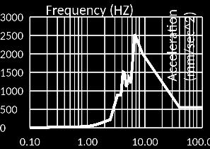
11 Aircraft Impact Analysis (Dynamic) Time History of the Side Impact Force of Aircraft for half of the target
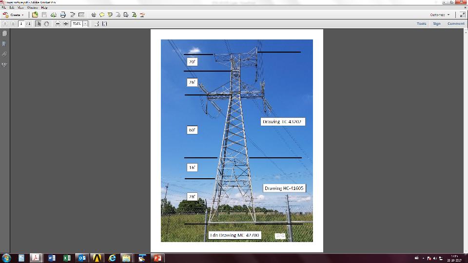
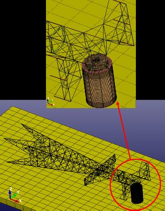

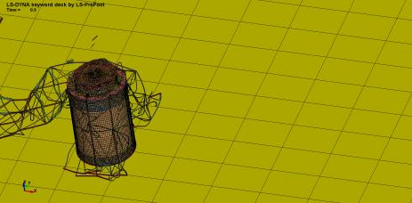
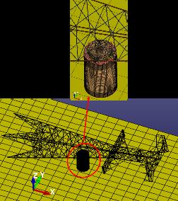

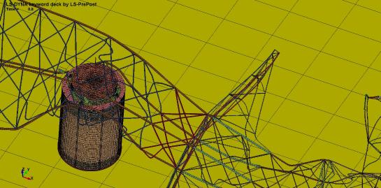
12 Transmission Tower Impact Analysis (Dynamic) FE model After Impact Before Impact Before Impact After Impact

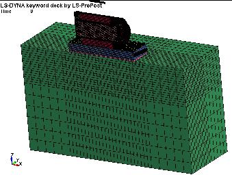
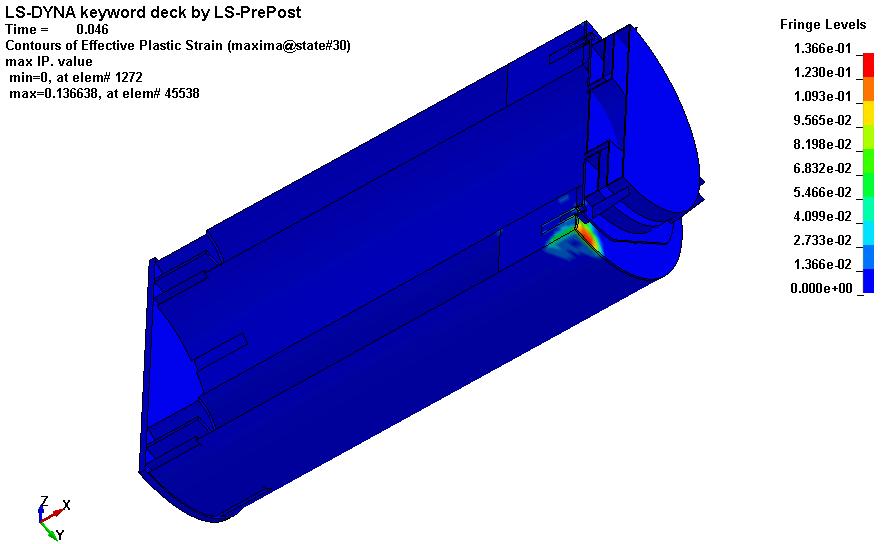
13 Side Drop Analysis (Dynamic)

14 Bridge Crane Analysis (Static + Dynamic)


15 Gantry Crane Analysis (Static + Dynamic)


16 Transport Frame Analysis (Static + Dynamic)

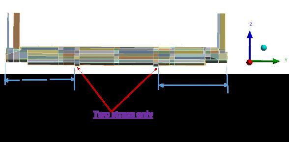
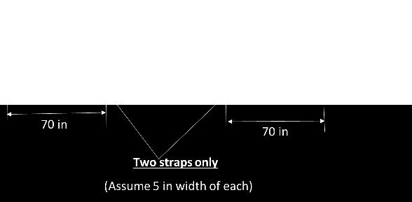

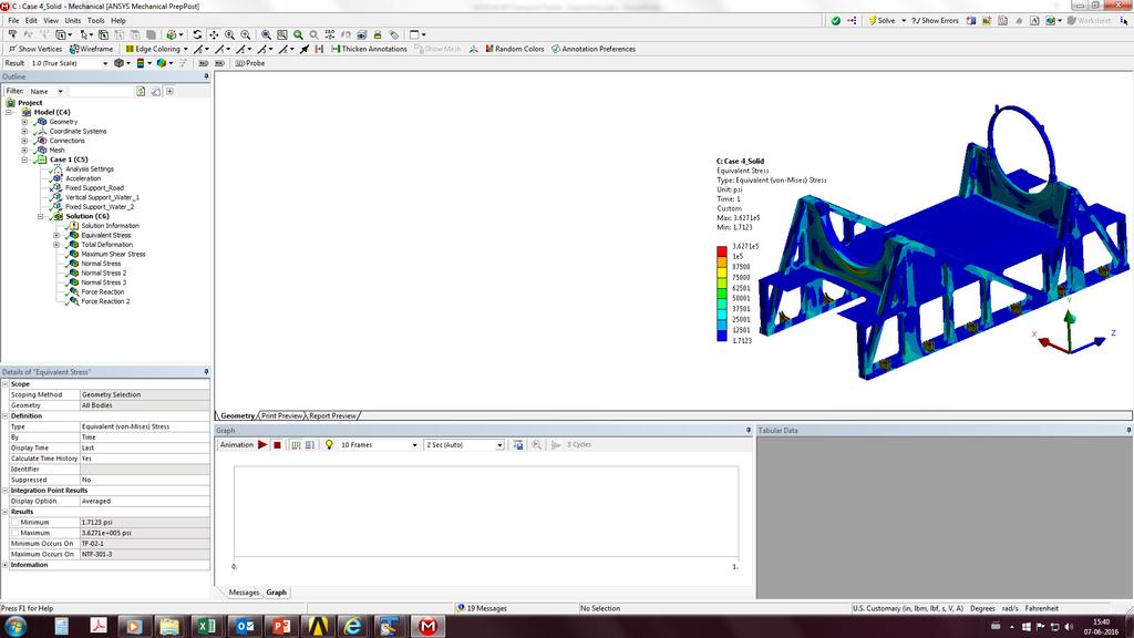
17 Lifting Analysis (Static)


18 Heat Exchanger Analysis (Static + Dynamic) (Flange Opening + Bolts)


19 Steam Duct Analysis (Static + Dynamic)

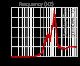
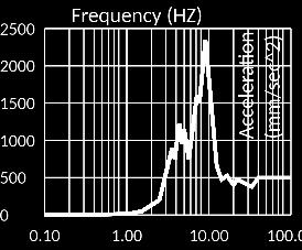
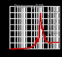
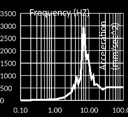
20 Stack Seismic Analysis (Static + Dynamic)

")
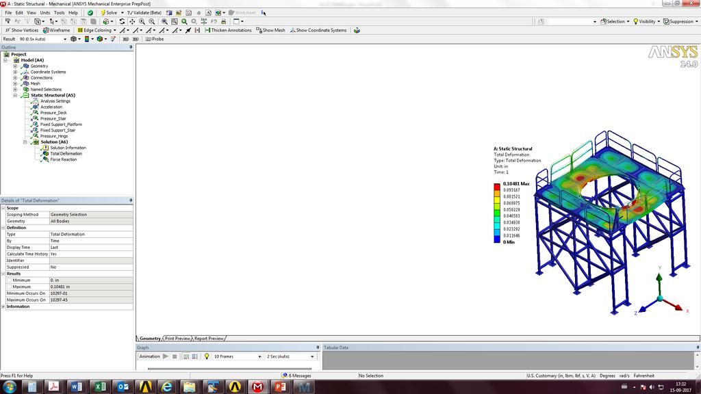
21 Work Platform Analysis (Static)

")

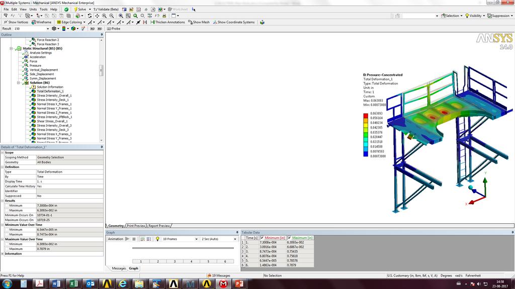
22 Work Platform Analysis (Static) Top View Bottom View

")

23 Heavy Duty Stand Analysis (Static) Without Top Platform Lower section


24 Bolt Analysis Composite Blades joint (Static) Blade Bolt Joint Analysis (more than 50m). Use TINY command to simulate the highly nonlinear contact models. Pre-tension, operating loads (tension and compression) with nonlinear contact analysis. Find the allowable strength of the bolt joint at critical locations for different Blade loads. Create and use the macros for pre and post processing the results. Exploded view Bolt Joint analysis Model

25 Transient Analysis for Wind Turbine Blade (Dynamic) Winglet ESTOP Transient Analysis. Create and use the macros for application of time history loads. Find out the critical time points and locations for maximum deformations. Create and use the macros for post processing the time history plots. Time Vs Load Plot Time Vs X-Displacement plot Time Vs Y-Displacement plot Time Vs Z-Displacement plot Time Vs Rot Z-Displacement plot Winglet FE Model Time Vs Displacement plots at Node = Time History Plots
 Solid modeling of single lap joint based on given reference paper (Methods of Analysis and Failure Predictions for Adhesively Bonded Joints of Uniform and Variable Bondline Thickness, Page 3-12")
26 Trailing Edge Glue Modeling for Composite Blades Single Lap Joint Analysis by Using FEMCI Tutorial ( Solid modeling of single lap joint based on given reference paper (Methods of Analysis and Failure Predictions for Adhesively Bonded Joints of Uniform and Variable Bondline Thickness, Page 3-12 to 3-16). Created and used the macros for creation of spring and coupling pairs between individual nodal sets. Find out the peel and shear stress at the individual layer of nodal set. Created and used the macros for extracting the required stress plots (Peel and shear) based on NASA formulations. Peal and Shear Stress Plots Single Lap Joint analysis FE Model

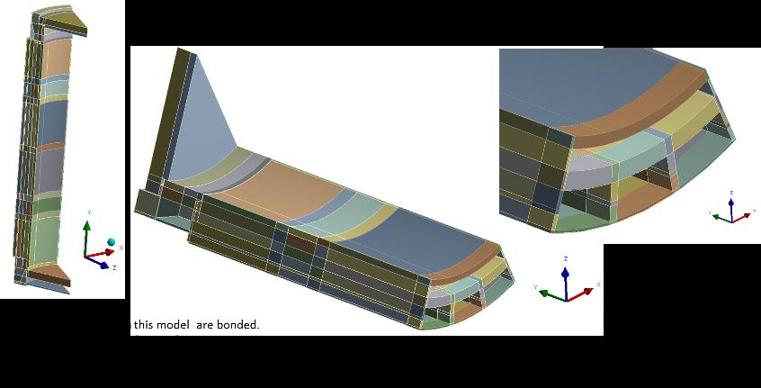
27 Lifting Analysis - Composite Blade
. Solid modeling of composite Caps, which will be used to protect the blade edge.")
.")
28 Lifting Analysis - Composite Blade (Static) GE 40 Blade Lifting Analysis (To eliminate the expense of one lifting machine). Solid modeling of composite Caps, which will be used to protect the blade edge. Solid modeling of Liners, used to protect the blade and composite caps. Solid modeling of strap for lifting the blade. Used weak spring concept for solving the problem (Better convergence). Find out the deflection at the critical locations. Blade Lifting analysis FE Model


29 SIMULATION PROJECTS WIND TURBINE Nacelle & Secondary Structure Bed Plate Drive Carrier Generator Frame Hub Platform Blade
.")


30 Low Noise Tip Swap Bolted Joint Analysis (Static) 40 Low Noise tip swap Bolted Joint Analysis (Base line, Modified and Winglet models with different design loads ). Resolve bending moments into flap and edge components to get final tension and compression loads for different load case. Pre-tension, operating loads (tension and compression) with nonlinear contact analysis. Use TINY command to simulate the highly nonlinear contact models. Find the allowable strength of the bolt joint at critical locations for different Blades. Create and use the macros for pre and post processing the results. Bolt Joint Model Bolt Joint FE Model
31 WIND HUB OVALIZATION (Static) Objective To find out the ovalization effect of hub for the unit load cases. Highlights The reference model was analyzed for the unit load case and the results were co-related with the client results to ensure and define the right methodology to be followed for rest of the analysis. The New hub model was analyzed for the ovalization effect at the flange location along with the different combinations of other hub assembly components such as shaft pitch bearing inner / outer races & composite blades. The weight reduction was done in new model by removing material at less stress region.


32 SECONDARY STRUCTURE ANALYSIS Objective To analyze the secondary structure assembly from stress point of view. To address the concerns about the strength when the structure was assembled/lifted individually. Highlights Nacelle was assembled with the secondary structure to simulate the wind loads acting on the Nacelle. The total assembly were analyzed for various load cases like wind, snow, gravity and service loads. The assembly was checked for strength when they were lifted individually. Involved in the project from the Conceptual stage Participated in Conceptual Design Reviews.


33 STRENGTH ASSESSMENT of 1st & 2nd STAGE CARRIER Objective Strength assessment of 2.5 MW 1 st stage and 2 nd stage carrier for 2.75 MW load conditions Highlights Unit load analysis of the carrier. Analysis for 1x and 3x load Tilt moment analysis of 1 st and 2 nd stage carrier Extreme Load analyses of 1 st and 2 nd stage carriers Hot spot extraction and unit stress extraction of carriers Fatigue life calculation of hotspots


34 WIND TOWER FE MODELING AUTOMATION Objective Geometric and Finite Element Modeling Automation of Wind Tower and Wind Platform. Automation Highlights The tower consists of concrete arc, flat panels with concrete fillers, steel columns, adaptor, foundation, tendons, bolts & Nuts. The parametric tower project was developed using Unigraphics & ANSYS. Various design parameters were controlled using expressions in UG which aided in faster creation of different types of geometry. APDL codes were used in ANSYS to automate the whole FE modeling process. The Final scripts developed using UG and ANSYS resulted in a huge cycle time reduction of the process.


35 Optimization - Torque Beam Optimization Objective: Redesign the torque beam for 4.0 MW Offshore to sustain the weight of the generator in case of a broken shaft scenario Highlights: Manual iterations to improve the stiffness of the beam Ansys Workbench optimization to obtain a new shape


36 PILLOW BLOCK STRENGTH ANALYSIS Objective Identify the critical regions in the pillow blocks which fail the fatigue life criterion. Highlights Unit load analysis is performed to find the hot spot regions. Unit stress extraction and Fatigue life calcluations are performed on those hotspots to estimate the stress reserve factor. Extreme load analyses for 3.5MW and 4 MW loading are performed to ensure the strength of pillow blocks.


37 WIND SINGLE PIECE FRAME STRENGTH ASSESMENT (DRILL HOLE ANALYSIS) Objective Bed plate strength analysis with drill holes on the crack tip. The Cracks are straight and Arc types on the weld location and in the stiffener plate Highlights In the field, the cracks were observed in the stiffener of the bed plate. A drill hole was introduced at the tip of the crack to stop the progression further. The finite element model setup was done similar to the field crack and a drill hole was introduced at the tip of the crack. It was observed that the stresses are smoothly distributed on the drill hole surface that helped to stop the crack progression with extended life of the bed plate. The analyzed helps to understand the optimized hole diameters and the effective location where the holes needs to be introduced which gives maximum life. The Value addition was given on the hole shape with blend on the edges.


38 BEDPLATE STRENGTH ASSESSMENT Objective The objective of this work is to obtain certificate from certifying agency TÜV by doing fatigue and extreme load analysis to show that the 1.5 Cast Bedplate has adequate strength margin for all configurations. Highlights Fatigue tool was used to do Fatigue analysis for 12 different Configurations. Extreme load analysis were done for all the load cases. SRF values were reported and the critical hotspots were identified.
39 Static Test Optimization Tool 50.2 Static test optimization tool (Excel). Reverse calculation of Flap and Edge test moments. Solve the force and moment equation with the help of least square method. Create the code in Visual Basic for of the vertical and horizontal loads based on below variables. 1. Saddle Location 2. Saddle Weight 3. Blade Mounting Angle 4. Load case bin 5. Minimum Load Ratio (110%) 6. Minimum the vertical and horizontal loads 7. Blade length limit for optimization (up to 70 % of blade length) Find out the optimized values of Vertical and horizontal loads by using VB code. Code is generalized in such a way that it can be use for other blades. Well Appreciated for the approach and effort by Mr. Venkateswara kaval and Mr. Nivesh Pandya Contribution by Arvind and Sailendra (Work in progress).
40 Buckling Analysis of Composite Blade Blade (more than 40 m) Buckling Analysis by Blade Detail Design Tool. Extract the Buckling envelops by using Blade Detail Design Tool Find out the Critical buckling modes under different bins. 5 th mode 15 th mode, (Bending and Twisting)
41 Contact Zacq Consultants Address - Block D-1, Plot No 17 /9, MIDC, Chinchwad, Pune Mobile: us: zacqconsultants@gmail.com
42 Thank You