Technical Documentation
|
|
|
- William Mason
- 5 years ago
- Views:
Transcription

1 Technical Documentation Underground Container F-Line 1.500L, 3.000L, 5.000L, 7.500L, L
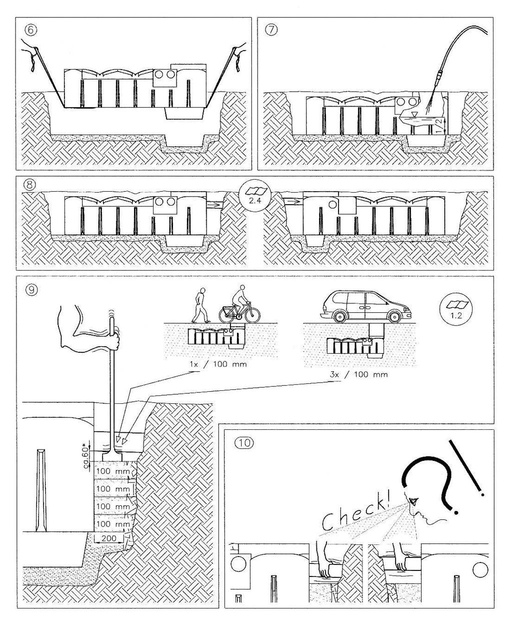
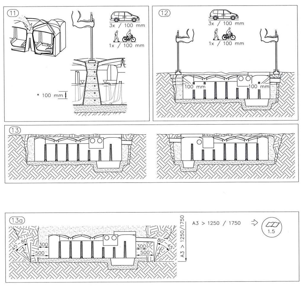
2 1. Location 1.1. Position to buildings The excavation space must not be within the minimum distance to buildings, see point 3 figure 1. The tank may only be built over if the appearing loads are not higher than the traffic loads Traffic conditions Loading class A15 (e.g. pedestrian, cyclist): no special equipment necessary. Loading class B (passenger car, minibus; max. axle loading 2,2 Tonne): Driveable complete set I and II. Minimum distance from tank top to the earth's surface: 600 mm 1.3. Ground conditions The tanks may lie in ground water and/or surface water up to the tank top max. (shoulder height; see figures under point 4). The soil coverage must be at least half as high as the immersion depth in the ground / surface water (lifting protection). In non permeable ground the depth may not exceed 250 mm Hillside situation The soil of the area has to be checked for possible soil movement (DIN 1054 edition 1/2003, E DIN 4084 edition 11/2002) and if necessary it will need to be secured with a supporting structure (e.g. a wall). Further information is available at the local public authorities and building enterprises 1.5. Installation details In clay ground conditions: 1.75-m depth of the excavation (picture 2 and 13a under point 3) no angle of repose necessary. The excavated area should be wide to allow compression of the filling material. (200 mm in picture 2 under point 3). With installations deeper than 1.75 m an area of 500 mm is necessary; the tank should be covered with at least 300 mm thick of filling material (picture 13a under point 3). In loose ground conditions (coarse sand, gravel) the above information is valid for 1.25-m excavation depth. Also with excavated area widths of 500 mm, in the pictures from 3 to 12 as well as 13a, shown installation steps are valid Further criteria Existing pipelines, pipes, vegetation as well as other specifics must be considered, so that damage or hazards will be avoided. The soil coverage from the tank shoulder (point 4) may be up to a maximum 1.5 m.
3 2. Installation 2.1. Backfill material at the tank (backfill, bedding; point 3 figures 2, 3, 4, 13 and 13a) The backfill material has to be well compactable and permeable to water, allowing a close packing and no damage the surface of the tank. If the filling material contains sharp or sharpedged components, the wall of the tank has to be protected by a sandy coating Sand -gravel mixtures (SW and GW to German Institute for Standardization and ENV 1046) are the most favourable filling materials, because they have a grain line which consists of several grain sizes with only a low amount of fines (fines: under Ø 0,06mm). At the description of the mixtures the first number gives the mesh width (simplified Ø) of the smallest grain and the second one those of the biggest grain: e.g., 0/32; 2/16; 2/8; 2/32; 4/16. Which mixtures are available, strongly depends on the regional supplies Concrete gravel, or treated concrete rubble, with a particle size of 0/32 mm is particularly well suited for use in clay/loam soil conditions with ground water and a high water table. When ground water and a high water table are present, it is particularly important to ensure good compaction, especially at hard to reach places Stone Chippings -crushed rock particles between 2/32 mm in size and is primarily suited as a filling material; however due to its sharp edges, the tank must be protected against damage, for example using a sand coating Excavation, sand and gravel mixture with mixed particle sizes is suitable for use as a filling material when it meets the criteria listed under Item Top soil, clay, loam and other types of cohesive soils are not suitable filling materials Filling beyond the backfill Excavated soil or other material can be used if this is stable and permeable Compression around the pump sump (1500L-5000L) The area around the pump sump must be very meticulously compressed. To compress the area behind the pump sump the material must be filled in gradually and pressed down with a suitable device, e.g., a roof batten.
4 2.3. Backfilling and compaction methods The backfilling and compaction methods to be used are described in Section 3 (Installation instructions) Methods that are not to be used include in particular adding water. Adequate compaction is not achieved and the mixture of particle sizes combine in such a way that the compaction is unstable Base layer driveable version: A range of grain size 2/45 must be used 2.4. Pipes The feed pipe should be laid with a fall to the tank (>1%). And must be a sealed pipe direct from the gutter. Do not use open gullies or P traps at the base off the downpipes The overflow / drain pipe should have a deeper fall away from the tank than the fall from the feed pipe to the tank The service pipe is to be installed to prevent any flooding from the tank entering the service room (e.g., cellar) if the tank is full. This can be achieved, for example, by a high enough incline of the pipe from the house to the tank. Or by the installation of a seal in the ductwork for cables The pipes have to be installed in such a way that frost damage is avoided. This is to be arranged according to the local climatic circumstances, if necessary in co-ordination with the local authorities.
5 3. Installation guide Notes for further information in chapter
6
7
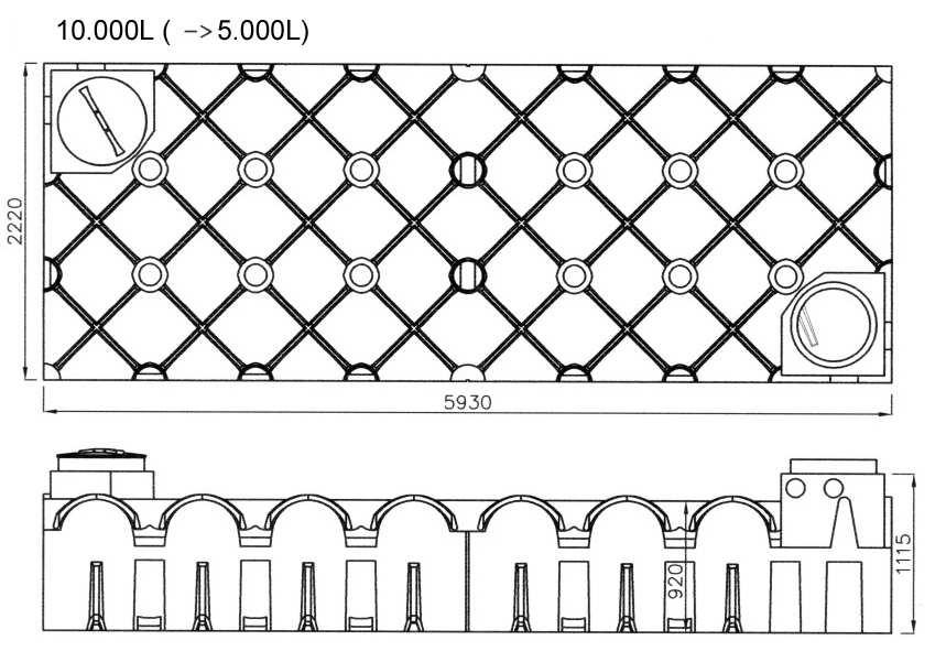
8 4. Main dimensions and positions of the standard connections A : Connection service pipe DN 100 B : Connection inflow DN 100 C : Connection overflow DN 100 D : Pump basin
9 A : Connection service pipe DN 100 B : Connection inflow DN 100 C : Connection overflow DN 100 D : Pump basin
10 A : Connection service pipe DN 100 B : Connection inflow DN 100 C : Connection overflow DN 100 D : Pump basin

11 7.500L B A C A : Connection service pipe DN 100 B : Connection inflow DN 100 C : Connection overflow DN 100
12


13 5. Optional Accessories Shaft coverage Top Cover according to DIN 1989 Walk-on Plastic Cover, for 600mm shaft-systems with safety latch according to EN External diameter 648 and profile according to DIN A Safety latch closed B Safety latch opened
14 Shaft coverage TwinCover according to DIN 1989 Walk-on Plastic Cover, for 600mm shaft-systems with safety latch according to EN and integrated inspection opening, which is lockable. External diameter 648 mm and profile according to DIN