Raritan Bay and Sandy Hook Bay, Port Monmouth, NJ Flood Risk Management Project
|
|
|
- Hope Charla Wood
- 5 years ago
- Views:
Transcription


1 Raritan Bay and Sandy Hook Bay, Port Monmouth, NJ Flood Risk Management Project Middletown, NJ USACE - New York District September 2, 2014 US Army Corps of Engineers
2 Raritan Bay and Sandy Hook Bay, Port Monmouth, NJ Flood Risk Management Project Authority Overview Estimated Cost, Non-Federal Sponsor and Cost Share Phases and Features Project Overview Walk thru Project Features Schedule Comments 2
3 Authority The project is authorized for construction under Section 101 of the Water Resources Development Act of The authorization provides for hurricane and storm damage reduction, in the Raritan Bay and Sandy Hook Bay, Port Monmouth, New Jersey. Public Law 113-2, the Disaster Relief Appropriation Act of 2013, Chapter 4 3
4 Project Cost & Cost Share Project Cost $104,691,819 Non-Federal Sponsor: Executed PPA with NJDEP on 31 January 2014 Cost Share Initial Construction: 100% Federal Renourishments: 50% Federal, 50% NonFed Operation & Maintenance: 100% NonFed 4

5 Port Monmouth, NJ Pews Creek Route 36 Compton Creek
6 6 BUILDING STRONG
7 Phases and Features Phase I (Under construction) Dune Groin Pier Extension Phase II (Under design) Tide Gate Pump Station(s) Levee(s) Floodwall(s) Road Closure Structures Interior Drainage Structures Mitigation 7
8 Groin Port Monmouth Locations: Length= 305 LF Crest Width= 13 ft 8
9 Beachfill Port Monmouth Beachfill: -Dune Elevation 15 NAVD (16 NGVD) 9
10 Pier Extension Port Monmouth Locations: -Extend Pier by 195LF -New ADA Ramp 10
11 Environmental Requirements Phase I Endangered Species Act consultation ongoing (sturgeon, whales, sea turtles) NEPA complete (ROD 2008; FONSI 2009) Water Quality/Federal Consistency rec d (May 2013) Benthic, T&E species, and dune planting monitoring Phase II Supplemental NEPA: update EIS & design changes Update Wetland Delineation/Geotechnical Boring Permit Pre-Application Meeting for other permits needed Wetland Mitigation Required: conversion of 12.8 acres of Phragmites to Spartina dominated plants Wetland mitigation and tidal exchange monitoring 11

12 Mitigation Component 12
13 Design to Construction Design Documentation Report (DDR) Value Engineering (VE) Groin was added during the VE of Phase I Engineering Design Report(EDR) Coordinate with the Non-Federal sponsor Some items may require timely response District Quality Control Agency Technical Review Independent External Peer Review BCOES 13
14 14 BUILDING STRONG
15 Pump Station Port Monmouth Locations: Pump Station at Pews Creek- 120 cfs Pump Station at Compton Creek-60cfs (sizes and hydraulics need to be finalized) 15
16 16 BUILDING STRONG
17 Port Monmouth Locations: Pews Creek- approx 40 w x 21 h Tide Gate Through Value Engineering the following gates were considered: Stoplogs Obermeyer Gate Tainter Gate Sector Gate Roller Gate Lift Gate Swing gate 17
18 Total Relative First Costs for Tide Gate Alternatives Table is a comparison of the relative first costs of various tide gate alternatives looking at the major cost drivers of concrete, gate weight, and area required for dewatering. The most cost effective option is the vertical lift gate. The vertical lift gate and tainter gate are the most cost effective options in comparison with the other types of gates.
19 Gate Life Cycle Cost Analysis FIRST COST PRESENT ANNUAL COST MAJOR MAINTENANCE COST LIFE CYCLE COST (Present Worth) VERTICAL LIFT GATE (Carbon Steel) $2,073,167 $281,467 $316,276 $2,670,911 VERTICAL LIFT GATE (Stainless Steel) $2,747,406 $281,467 $3,028,873 Rolling Gate (Carbon Steel) $3,027,533 $844,402 $347,904 $4,219,839 Tainter Gate (Carbon Steel) $2,682,759 $281,467 $395,345 $3,359,571 Sector Gate (Carbon Steel) $4,411,260 $1,125,870 $434,879 $5,972,009 Table is a comparison of the present value life cycle costs of the various tide gate alternatives. The vertical lift gate is the most cost effective option in comparison with the other types of gates.

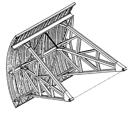
20 Lift Gate
21 Lift Gate
22 Advantages Low first and life cycle cost Simplified fabrication and installation (nom 10 x 24 segments) Simplified cable and drum operation powered by electric motor Self cleaning bottom seal area as flows will be concentrated at gate bottom during closure thus clearing debris and silt (V=QA). The weight of the gate will free the rollers from ice End support of rollers results in stability during high wind events Corrosion potential is minimized due to gate being out of the water when not in use

23 Disadvantages Vertical lift requires piers that extend approximately 25 ft above the top of the protection elevation (note: can add architectural feature such as fractured fin or embedded image to enhance appearance).

24 Lift Gate

25 Tainter Gate


26 Tainter Gate
27 Disadvantages Fairly complex framing On site assembly more complicated since gate cannot be designed in segments Major maintenance (painting) would have to be done on site since gate cannot be disassembled for shipping Tainter Gate requires piers that extend approximately 17 ft above the top of the protection elevation Higher first cost of concrete support structure


28 Port Monmouth Levee: Various locations- 7,275 LF Elevation 14 NGVD or 13 NAVD Required vegetation free 15 from base Levee 28
29 29 BUILDING STRONG
30 Typical Levee Cross Section 30
31 Floodwall Port Monmouth Floodwall: Various locations- 4,352 LF Elevation 14 NGVD or 13 NAVD Required vegetation free 15 from base 31
32 32 BUILDING STRONG
33 Typical Floodwall Cross Section 33

34 Floodwall 34


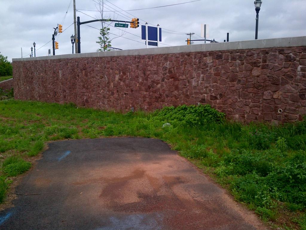
35 Examples 35 BUILDING STRONG


36 Examples 36


37 Road Closure Gate Port Monmouth Locations: Port Monmouth Road- 40 w x 4 h Broadway 40 w x 8 h Campbell Avenue 40 w x 8.5 h Could be a roller or swing gate depending on location 37
38 38 BUILDING STRONG

39 Interior Drainage Port Monmouth Locations: Pump Station at Pews Creek Pump Station at Compton Creek Interior Drainage structures through the levee/floodwall 15 drainage structures with flap valve and sluice gate 810 LF of Storm water diversion pipe 39

40 40 BUILDING STRONG
41 Schedule Could complete entire project prior to 2020 Requires timely decision making by all stakeholders Need to obtain Phase II permits 41
42 COMMENTS / QUESTIONS 42